

Page 1
Switch-Pro™
w/ Compact Relay Controller
AU13 & AZ13 Series
Owner’s Manual
Flowline, Inc. |. 10500 Humbolt Street, Los Alamitos, CA 90720. p 562.598.3015. f 562.431.8507. w flowline.com MN301450 Rev A
Page 2

Introduction / Table of Contents Step One
Intended for side wall installation, the general purpose level switch package provides reliable liquid level
detection with a 16A compact level controller for pump or valve control. The optional flash alarm brings
attention to alarm conditions. Offered in two level sensor technologies, select the type and material based
upon your application media. This liquid level switch package is widely applied in bulk storage and process
tank level applications for high level control or low level control.
FEATURES
Rugged Polypropylene, Ryton® or PFA sensor for corrosive liquids applications.
Fail-Safe relay control of pumps, valves or alarms with a 0.15 to 60 second delay.
Polypropylene enclosure rated NEMA 4X with swivel base for conduit alignment.
Optional flashing alarm brings immediate attention to level alarm conditions.
Invert switch changes relay state from NO to NC without rewiring.
Offered in two sensing technologies for broad application coverage: ultrasonic and vibration.
TABLE OF CONTENTS
Specifications: ....................................................................................................................................................... 3
Dimensions: .......................................................................................................................................................... 4
Components: ........................................................................................................................................................ 5
Standard Configuration: ............................................................................................................................ 6
Technology: .......................................................................................................................................................... 7
Vibration: ................................................................................................................................................... 7
Ultrasonic: ................................................................................................................................................. 8
Safety Precautions: ............................................................................................................................................... 9
Make a Fail-Safe System: ....................................................................................................................... 10
Getting Started: ................................................................................................................................................... 11
Guide to Controls: ................................................................................................................................... 11
Electrical: ............................................................................................................................................................ 12
Connecting Switch to Input Terminals: ................................................................................................... 12
VAC Power Input Wiring: ........................................................................................................................ 12
Changing from 120 to 240 VAC: ............................................................................................................. 12
Relay Input Wiring: .................................................................................................................................. 13
Strobe Alert Output: ................................................................................................................................ 13
Installation: .......................................................................................................................................................... 14
Install in a dry location: ........................................................................................................................... 14
Application Examples: ........................................................................................................................................ 15
High Alarm: ............................................................................................................................................. 15
Low Alarm: .............................................................................................................................................. 15
Appendix: ............................................................................................................................................................ 16
Controller Logic: ...................................................................................................................................... 16
Troubleshooting: ..................................................................................................................................... 16
Maintenance: ...................................................................................................................................................... 17
Cleaning Procedure: ............................................................................................................................... 17
Current test (sensor alone): .................................................................................................................... 17
Warranty, Returns and Limitations: .................................................................................................................... 18
| 2 MN301450 Rev A
Page 3
Specifications / Dimensions
Accuracy: ± 1mm in water
Repeatability: ± 0.5mm in water
LED indication: Power, relay and sensor status
Supply voltage: 120/240 VAC @ 50-60 Hz.
Consumption: 0.25A maximum
Contact type: (1) SPDT Relay
Contact rating: 250 VAC @ 16A, ½ Hp
Contact output: Selectable NO or NC
Contact delay: 0.15 - 60 seconds
Process temp.: F: -40°to 176° / C: -40°to 80°
Ambient temp.: F: -40°to 140° / C: -40°to 60°
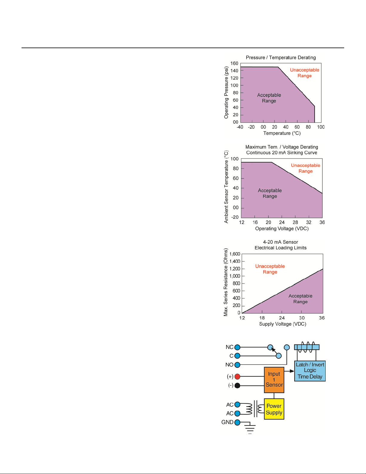
Pressure: 150 psi (10bar) @ 25 °C, derated
@ 1.667 psi (0.113 bar) per °C
above 25 °C.
Enclosure rating: NEMA 4X (IP65)
Enclosure material: -_11_: PP (U.L. 94 VO & PC)
-_12_: PP (U.L. 94 VO)
Conduit entrance: Single, 1/2" NPT
Wetted material: AZ13-11__: Ryton®
AU13-11__: PP
AU13-11__: PFA
Enclosure mount.: 3/4” NPT (G)
Enclosure rotation: 300°swivel base
Mount. Gasket: Viton® (G version only)
Classification: General purpose
Certificate number: LR 79326-3
CE compliance: EN 61326 EMC
EN 61010-1 Safety
Step Two
STROBE ALERT
Flash type: Xenon tube
Flash frequency: 1 per second
Strobe life: 10M cycles
Supply voltage: 120 VAC, 50-60 Hz.
Consumption: 3 Watts max.
Material: Polycarbonate
Enclosure rating: NEMA 4X (IP65)
Color: Amber
MN301450 Rev A 3 |
Controller Logic
Page 4
Specifications / Dimensions (continued) Step Two
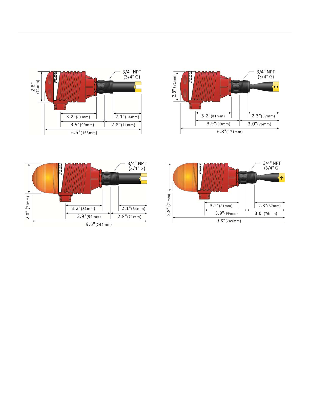
DIMENSIONS
Ultrasonic w/o Strobe
AU13-112_ & AU13-212_ Series
Ultrasonic w/ Strobe Alert™
AU13-111_ & AU13-211_ Series
Vibration w/o Strobe
AZ13-112_ Series
Vibration w/ Strobe Alert™
AZ13-111_ Series
| 4 MN301450 Rev A
Page 5

Components Step Three
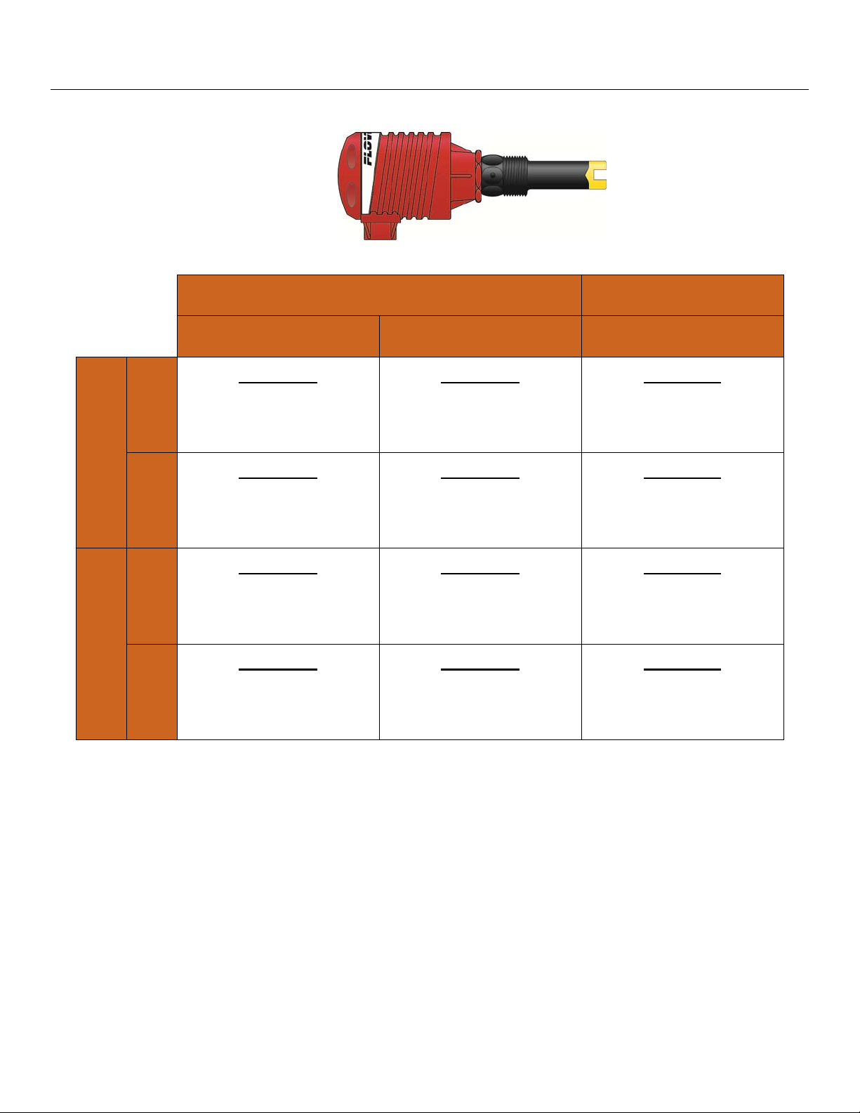
ABOUT SWITCH-PRO™
Flowline’s Switch-Pro™ with Compact Relay Controller is a single-point mounting system for installing through
the side-wall of a tank. The compact relay controller features a 120/240 VAC controller with a 250 VAC, 16A,
1/2Hp SPDT relay contract.
Part
Number
AU13-1110
240 VAC
Option
CE
Option
N/A
Thread
NPT
Strobe
Alert
Yes
Sensor
Material
AU13-1114 G
PP
AU13-1120
AU13-1124 G
Add
(-CE)
AU13-2110
N/A
AU13-2114 G
AU13-2120
AU13-2124 G
Add
(-E)
Add
(-CE)
AZ13-1110
N/A
NPT
No
NPT
Yes
PVDF
NPT
No
NPT
Yes
AZ13-1114 G
Ryton® Vibration
AZ13-1120
AZ13-1124 G
Add
(-CE)
NPT
No
Sensor
Technology
Ultrasonic
Owner’s Manual
RELAY CONTROLLER
The level switch is pre-wired before shipment to the 2-pole terminal strip [(+) & (-)]. The technologies used to
indicate level is either Ultrasonic or Vibration. Both the sensing technologies feature similar wiring/power
configuration. The Compact Relay Controller provides a 1/2” Conduit connection and 6 poles for wire
termination of power and relay contact. Use the AC, AC and GND terminals for providing power. Use the NC,
NC and COM terminals for interfacing to the relay contact.
MN301450 Rev A 5 |
Page 6
Components (continued) Step Three
STANDARD CONFIGURATION
AU13-_1_ _ or AZ12-11_ _
AU13-1120 Shown
Ultrasonic Vibration
PP PFA Ryton®
¾”
NPT
¾”
Strobe Alert
G
¾”
NPT
No Strobe
¾”
G
AU13-1110
1 x LU10-1405
1 x LC10-1002
AU13-1114
1 x LU10-1425
1 x LC10-1052
AU13-1120
1 x LU10-1405
1 x LC10-1001
AU13-1124
1 x LU10-1425
1 x LC10-1051
AU13-2110
1 x LU10-2405
1 x LC10-1002
AU13-2114
1 x LU10-2425
1 x LC10-1052
AU13-2120
1 x LU10-2405
1 x LC10-1001
AU13-2124
1 x LU10-2425
1 x LC10-1051
AZ13-1110
1 x LZ12-1405
1 x LC10-1002
AZ13-1114
1 x LZ12-1425
1 x LC10-1052
AZ13-1120
1 x LZ12-1405
1 x LC10-1001
AZ13-1124
1 x LZ12-1425
1 x LC10-1051
| 6 MN301450 Rev A
Page 7

Technology Step Four
VIBRATION SWITCH (AZ13-11_ _ SERIES)
The vibration switch (tuning fork) operates at a nominal frequency of 400 Hz. As the switch becomes
immersed in a liquid or slurry, a corresponding frequency shift occurs. When the measured frequency shift
reaches the set point value, the switch changes state indicating the presence of a liquid or slurry medium. For
optimum performance and proactive maintenance, the sensor automatically adjusts for coating, and if
necessary, outputs a preventative maintenance alarm.
Vibration Switch NPT Version
Vibration Switch G Version
Do not squeeze the forks together. Doing so could damage or break the sensor and void the
warranty.
When powering up the AZ13-11__ series, the start-up procedure requires the switch to cycle through a wet
condition for 1/2 second in order to determine an initial resonance. The relay within the controller will switch
between open and close during this sequence.
LZ12 SPECIFICATIONS
Sensor material: Ryton® (glass fill)
Viton® cable grommet
Cable jacket mat’l: PP
Cable type: 5-conductor, #24 AWG
(shielded)
CONFIGURATIONS
Part Number
Material
(body)
Material
(cable)
Thread
(inside x outside)
LZ12-1405 Ryton Polypropylene ¾” NPT x ¾” NPT
LZ12-1425 Ryton Polypropylene ¾” R x ¾”G
MN301450 Rev A 7 |
Page 8

Technology (continued) Step Four
ULTRASONIC SWITCH (AU13-11_ _ & AU13-21_ _ SERIES)
The Ultrasonic level switch generates a 1.5 MHz ultrasonic wave from a miniature piezoelectric transducer
located on one side of the gap within its sensing tip. Another piezo transducer, located on the other side of the
gap, acts as a microphone, picking up the sound wave. When liquid enters the gap, there is a change in the
speed the wave crosses the gap. This change in the speed of sound identifies whether the sensor is in liquid
or in air.
Tuning Fork NPT Version
Tuning Fork G Version
The sensor should be installed so that the liquid will drip out of the gap when the sensor becomes
dry.
LU10 SPECIFICATIONS
Sensor material: 1_ _5: PP
2_ _5: PFA
CONFIGURATIONS
Cable jacket mat’l: 1_ _5: PP
2_ _5: PFA
Thread
Part
Number
Length
Material
(body)
Material
(cable)
cable
side
X
sensor
side
LU10-1405 Long (4.5”) Polypropylene Polypropylene (¾” NPT) x (¾” NPT)
LU10-1425 Long (4.5”) Polypropylene Polypropylene (¾” R) x (¾”G)
LU10-2405 Long (4.5”) PFA PFA (¾” NPT) x (¾” NPT)
LU10-2425 Long (4.5”) PFA PFA (¾” R) x (¾”G)
| 8 MN301450 Rev A
Page 9

Safety Precautions Step Five
About This Manual: PLEASE READ THE ENTIRE MANUAL PRIOR TO INSTALLING OR USING THIS
PRODUCT. This manual includes information on the Switch-Pro™ with Compact Level Controller from
Flowline: AU13-11__, AU13-21__ & AZ13-11__. The units are identical except for the material of
construction and sensing technology of the sensor.
User’s Responsibility for Safety: Flowline manufactures a wide range of liquid sensors, controllers, and
mounting systems. It is the user's responsibility to select components that are appropriate for the
application, install them properly, perform tests of the installed system, and maintain all components. The
failure to do so could result in property damage or serious injury.
Proper Installation and Handling: Use a proper sealant with all installations. Never over-tighten the
components. Always check for leaks prior to system start-up.
Material Compatibility:
o Polypropylene (PP, a polyolefin): Sensor (AU13-11__ series only), Junction Box.
o Ryton: Sensor (AZ13-11__ series only).
o Polyvinylidene Fluoride (PVDF): Sensor (AU13-21__ series only).
o Make sure that the application liquids are compatible with the materials that will be wetted. To
determine the chemical compatibility between the components and its application liquids, refer to the
Compass Corrosion Guide, available from Compass Publications (phone 858-589-9636).
Electrical Shock Hazard: It is possible to contact components on the controller that carry high voltage,
causing serious injury or death. All power to the controller and the relay circuit(s) it controls should be
turned OFF prior to working on the controller. If it is necessary to make adjustments during powered
operation, use extreme caution and use only insulated tools. Making adjustments to powered controllers is
not recommended. Wiring should be performed by qualified personnel in accordance with all applicable
national, state and local electrical codes.
Flammable or Explosive Applications: DO NOT USE THE AU13-11_ _, AU13-21_ _ or AZ13-11_ _
Switch-Pro™ GENERAL PURPOSE SENSOR WITHIN CLASSIFIED HAZARDOUS ENVIRONMENTS.
Warning
The rating for the relay is 250 VAC, 16A, ½ Hp.
Flowline’s Switch-Pro™ level switches are not recommendable for use with electrically charged
application liquids. For most reliable operation, the liquid being measured may need to be
electrically grounded.
The sensing tip of the sensor must always be submersed in the liquid and never exposed to air.
The liquid temperature must remain constant and not change throughout the process
MN301450 Rev A 9 |
Page 10

Safety Precautions (continued) Step Five
Make a Fail-Safe System: Design a fail-safe system that accommodates the possibility of relay or power
failure. If power is cut off to the controller, it will de-energize the relay. Make sure that the de-energized
state of the relay is the safe state in your process. For example, if controller power is lost, a pump used to
fill a tank will turn off if it is connected to the Normally Open side of the relay.
While the internal relay is reliable, over the course of time relay failure is possible in two modes: under a
heavy load the contacts may be “welded” or stuck into the energized position, or corrosion may buildup on
a contact so that it will not complete the circuit when it should. In critical applications, redundant backup
systems and alarms must be used in addition to the primary system. Such backup systems should use
different sensor technologies where possible.
While this manual offers some examples and suggestions to help explain the operation of FLOWLINE
products, such examples are for information only and are not intended as a complete guide to installing any
specific system.
Relay Contact Rating: The relay is rated for a 16 amp resistive load. Many loads (such as a motor during
start-up or incandescent lights) are reactive and may have an inrush current characteristic that may be 10
to 20 times their steady-state load rating. The use of a contact protection circuit may be necessary for your
installation if the 16 amp rating does not provide an ample margin for such inrush currents.
Safety Cover: Based upon the part number selected, a safety cover has been placed within the
enclosure. Always replace the safety cover after any service.
Standard Version (Non-CE) CE Version (ex: AG12-1620-CE or AT14-3620-CE)
Open View of Controller (Non-CE) CE Version (ex: AU13-2120-CE or AZ13-1120-CE)
| 10 MN301450 Rev A
Page 11

Getting Started Step Six
The relay inside the controller is a single pole, double throw type; the controlled device can be connected to
either the normally open or normally closed side of the relay. A time delay from 0.15 to 60 seconds can be set
before the relay responds to the sensor input.
GUIDE TO CONTROLS
Below is a listing and the location of the different components for the controller:
Standard Version (Non-CE) CE Version
1. Power indicator: This green LED lights when AC power is ON.
2. Relay indicator: This red LED will light whenever the controller energizes the relay, in response to the
proper condition at the sensor input and after the time delay.
3. AC Power terminals: Connection of 120 VAC power to the controller. The setting may be changed to
240 VAC if desired. This requires changing internal jumpers; this is covered in the Installation section of
the manual. Polarity (neutral and hot) does not matter.
4. Relay terminals (NC, C, NO): Connect the device you wish to control (pump, alarm etc.) to these
terminals: supply to the COM terminal, and the device to the NO or NC terminal as required. The switched
device should be a non inductive load of not more than 16 amps; for reactive loads the current must be
derated or protection circuits used. When the red LED is ON and the relay is in the energized state, the
NO terminal will be closed and the NC terminal will be open.
5. Invert switch: This DIP switch reverses the logic of the relay control in response to the sensor(s):
conditions that used to energize the relay will make it turn off and vice versa.
6. Time Delay: After the input(s) change(s) state, this control sets a delay from 0.15 to 60 seconds before
the relay will respond.
7. Input 1A indicator: These amber LED will light immediately whenever the sensor attached to the
controller detects liquid and will turn off when it no longer detects liquid.
8. Input terminals: Connect the wiring from the sensors to these terminals: Note the polarity: (+) is a 13.5
VDC, 25 mA power supply (to be connected to the red wire of a Flowline sensor), and (-) is the return path
from the sensor (to be connected to the black wire of a Flowline sensor).
MN301450 Rev A 11 |
Page 12

Electrical Step Seven
Follow these steps for the electrical portion of this manual:
1. Confirm level switch is attached to the input terminals.
2. Provide 120/240 VAC power to the sensor.
3. Connect switched device to the relay terminals.
4. Attach strobe (if included) to the relay terminals.
1. Confirm level switch is attached (Connecting switches to input terminals):
The sensor provided is prewired. The level switch
will be wired with the Red wire to the (+) terminal
and the Black wire to the (-) terminal. Amber LED
is ON when the sensor detects liquid and OFF
when no
liquid is detected.
2. Provide 120/240 VAC power (VAC Power Input Wiring):
Observe the labeling on the controller on whether it is
configured as 120 or 240 VAC. Note: Polarity does
not matter with the AC input terminal.
CHANGING FROM 120 TO 240 VAC
1. Remove the two screws from the top of the printed
circuit board (PCB) and gently slide the PCB from
the housing. Use caution when removing the
PCB.
2. Located jumpers JWA, JWB and JWC on the
PCB.
3. To change to 240 VAC, remove jumpers from
JWB and JWC and place a single jumper across
JWA. To change to 120 VAC, remove jumper
JWA and place jumpers across JWB and JWC.
4. Gently return PCB into housing and replace the
120 VAC Configuration 240 VAC Configuration
two screws.
Standard Version (Non-CE)
CE Version
120 VAC Configuration 240 VAC Configuration
| 12 MN301450 Rev A
Page 13

Electrical (continued) Step Seven
3. Connect switched device to the relay (Relay Input Wiring):
The relay is a dry contact single pole, double throw type rated at
250 VAC, 16A, ½ Hp. The two terminals NO and NC (normally
open and normally closed) will be used in different applications
with C (common) used regardless of choice between NO or NC.
Note: the "normal" state is when the relay coil is de-energized
(the Red relay LED will be OFF). Regardless of the invert status
(ON or OFF), the normal state will always be when the Red LED
is OFF.
4. Attach strobe [Strobe Alert Output (AU13-111_, AU13-211_ & AZ13-111_ Series)]:
With the Strobe Alert wired NC; it can be used as a
high or low level alarm, depending on the setting for
the invert switch. The Strobe Alert can also be wired
NO. Note: the Strobe Alert™ shares the relay within
the sensor. The flashing alarm can be set to either
indicate when the switched device (pump, valve or
alarm) is active or not active.
MN301450 Rev A 13 |
Page 14

Installation Step Eight
THROUGH WALL INSTALLATION
Flowline’s Switch-Pro™ A_13 series may be installed through the side wall of a tank. The sensor has male 3/4"
NPT (3/4” G) threads on one side of a 15/16" wrench flat. This enables the user to select the sensor’s
mounting orientation, installed outside of the tank in.
ULTRASONIC ORIENTATION
Install the switch such that the gap is aligned up and down, allowing for liquid to easily leave the gap. Avoid
aligning the gap horizontally. This could allow material to collect on one of the flat surfaces in the gap. See
the illustrations below for further information.
VIBRATION ORIENTATION
Install the switch such that the forks are aligned up and down, allowing for liquid to easily leave the space
between the forks. Avoid aligning the gap horizontally. This could allow material to collect on one of the forks.
See the illustrations below for further information.
Warning
Do not squeeze the forks together. Doing so could damage or break the sensor and void the warranty.
Always install the Viton gasket with all versions of the AU13-_1_4 or AZ13-_1_4. The G threaded
version will not seal unless the gasket is properly installed.
INSTALL IN A DRY LOCATION
The controller housing is liquid-resistant and made of Polypropylene (PP). When installed properly, the
controller is not designed to be immersed. It should be mounted in such a way that it does not normally come
into contact with fluid. Refer to an industry reference to ensure that compounds that may splash onto the
controller housing will not damage it. Such damage is not covered by the warranty.
| 14 MN301450 Rev A
Page 15

Application Examples Step Nine
HIGH ALARM
The goal is to indicate when a high level of liquid is reached. This alarm point would be used to indicate when
the tank is full or to prevent a tank from over flowing. Switch-Pro™ will typically interface with alarms, pumps
or valves:
Tank is full:
o Primarily uses an alarm (visual, audible or both).
o Alarm will trigger (activate alarm device) when the sensor
becomes wet.
o Location of sensor determines the level of the alarm.
Prevent a tank from overflowing:
o Switch-Pro™ can be used as a redundant override that will
break power to the pump or valve, thus preventing the tank
from over flowing.
o Location of the sensor determines the level for the override.
Choose a location below where the liquid will actually
over flow from the tank.
o When liquid level lowers, Switch-Pro™ will become dry and
the pump circuit will close enabling the tank fill to begin
again.
Do not use Switch-Pro™ as the stop for an automatic
fill process unless a latching circuit has been added to control the start function.
LOW ALARM
The goal is to indicate when a low level of liquid is reached. This alarm point would be used to indicate when
the tank is empty, when it is time to re-order product or to protect a pump from operating while dry.
Tank is empty:
o Primarily uses an alarm (visual, audible or both).
o Alarm will trigger (activate alarm device) when the sensor becomes dry.
o Location of sensor determines the level of the alarm.
Re-order product:
o Primarily uses an alarm (visual, audible or both).
o Alarm will trigger (activate alarm device) when the sensor becomes dry.
o Location of sensor determines the level of the alarm.
Protect a pump:
o Switch-Pro™ can be used as a redundant override that will
break power to the pump, thus preventing the pump from
operating dry.
o Location of the sensor determines the level for the override.
Position the sensor above the location for the pump
inlet.
As long as the switch is wet, then there is liquid for
the pump to operate.
o When liquid level rises, Switch-Pro™ will become wet and the pump circuit will close enabling the
pump to operate again.
MN301450 Rev A 15 |
Page 16

Appendix Step Ten
CONTROLLER LOGIC
Please use the following guide to understand the operation of the controllers.
1. Power LED: Make sure the Green power LED is ON when power is supplied to the controller.
2. Input LED: Indicates the status of the level switch. The input LED on the controller will be Amber when
the switch is in contact with liquid (wet) and OFF when the switch is no longer in contact with liquid (dry).
3. Invert Operation: When the input LED turns Off and On, the relay L ED will also switch. With invert Off,
the relay LED will be On when the input LED is On and Off when the input LED is Off. With invert On, the
relay LED will be Off when the input LED is On and On when the input LED is Off.
4. Relay Operation: The relay may be wired either NO or NC. The normal state of the relay is when its LED
is Off. With the LED On, the relay is in the energized mode and all terminal connections are reversed.
TROUBLESHOOTING
PROBLEM SOLUTION
Controller is powered, but nothing
happens.
First check the Power LED to make sure it is Green. If not, check the
wiring, power and make sure the terminal is seated correctly over the 6pins.
A wet or dry condition is met but
the relay did not switch.
A wet or dry condition is met, but
the relay physically switches too
late.
Check the relay by switching the invert switch. Confirm that relay click
on and off as well as the relay LED.
Check the delay setting on the controller. The delay can be set from
0.15 to 60 seconds. Turning the delay slightly counter-clockwise will
reduce the reaction time. The delay affects both the make and break
side of the contact.
When a wet or dry condition is
met, the relay chatters on and off.
The liquid level has some waves which is causing the sensor to switch
between wet and dry conditions. Adding a little time delay will correct
this. A slight turn clockwise to the delay is all that is needed.
| 16 MN301450 Rev A
Page 17

Maintenance Step Eleven
GENERAL
The Switch-Pro™ level switch requires no periodic maintenance except to clean off any deposits or scaling
from the sensor tip as necessary. It is the responsibility of the user to determine the appropriate maintenance
schedule, based on the specific characteristics of the application liquids.
CLEANING PROCEDURE
1. Power: Make sure that all power to the sensor, controller and/or power supply is completely
disconnected.
2. Sensor Removal: Make sure that the liquid level is below the location of the sensor and the tank
is not pressurized. Carefully, remove the sensor from the installation. Replace the sensor with a 3/4”
NPT plug to insure that liquid does not leak out during this procedure. Do not re-install the SwitchPro™ if the threads are damaged.
3. Cleaning the Sensor: Use a soft bristle brush and mild detergent, carefully wash the Switch-Pro™
level switch. Do not use harsh abrasives such as steel wool or sandpaper, which might damage the
surface sensor. Do not use incompatible solvents which may damage the sensor's PP, Ryton or PVDF
plastic body.
4. Sensor Installation: Follow the appropriate steps of installation as outlined in the installation section of
this manual.
CURRENT TEST (SENSOR ONLY)
Use to verify if the sensor indicates a wet or dry condition. A power supply (typically 12 to 28 VDC) and a
multimeter [set to read current (mA)] are required. This test uses only two wires (Red and Black). The sensor
draws 5 mA (ultrasonic) or 8 mA (vibration) when it is dry, and 22 mA when wet. The White and Green wires
are not used.
MN301450 Rev A 17 |
Page 18

Warranty, Returns and Limitations Step Twelve
WARRANTY
Flowline warrants to the original purchaser of its products that such products will be free from defects in
material and workmanship under normal use and service in accordance with instructions furnished by Flowline
for a period of two years from the date of manufacture of such products. Flowline's obligation under this
warranty is solely and exclusively limited to the repair or replacement, at Flowline's option, of the products or
components, which Flowline's examination determines to its satisfaction to be defective in material or
workmanship within the warranty period. Flowline must be notified pursuant to the instructions below of any
claim under this warranty within thirty (30) days of any claimed lack of conformity of the product. Any product
repaired under this warranty will be warranted only for the remainder of the original warranty period. Any
product provided as a replacement under this warranty will be warranted for the full two years from the date of
manufacture.
RETURNS
Products cannot be returned to Flowline without Flowline's prior authorization. To return a product that is
thought to be defective, go to www.flowline.com, and submit a customer return (MRA) request form and follow
the instructions therein. All warranty and non-warranty product returns to Flowline must be shipped prepaid
and insured. Flowline will not be responsible for any products lost or damaged in shipment.
LIMITATIONS
This warranty does not apply to products which: 1) are beyond the warranty period or are products for which
the original purchaser does not follow the warranty procedures outlined above; 2) have been subjected to
electrical, mechanical or chemical damage due to improper, accidental or negligent use; 3) have been modified
or altered; 4) anyone other than service personnel authorized by Flowline have attempted to repair; 5) have
been involved in accidents or natural disasters; or 6) are damaged during return shipment to Flowline. Flowline
reserves the right to unilaterally waive this warranty and dispose of any product returned to Flowline where: 1)
there is evidence of a potentially hazardous material present with the product; or 2) the product has remained
unclaimed at Flowline for more than 30 days after Flowline has dutifully requested disposition. This warranty
contains the sole express warranty made by Flowline in connection with its products. ALL IMPLIED
WARRANTIES, INCLUDING WITHOUT LIMITATION, THE WARRANTIES OF MERCHANTABILITY AND
FITNESS FOR A PARTICULAR PURPOSE, ARE EXPRESSLY DISCLAIMED. The remedies of repair or
replacement as stated above are the exclusive remedies for the breach of this warranty. IN NO EVENT SHALL
FLOWLINE BE LIABLE FOR ANY INCIDENTAL OR CONSEQUENTIAL DAMAGES OF ANY KIND
INCLUDING PERSONAL OR REAL PROPERTY OR FOR INJURY TO ANY PERSON. THIS WARRANTY
CONSTITUTES THE FINAL, COMPLETE AND EXCLUSIVE STATEMENT OF WARRANTY TERMS AND NO
PERSON IS AUTHORIZED TO MAKE ANY OTHER WARRANTIES OR REPRESENTATIONS ON BEHALF
OF FLOWLINE. This warranty will be interpreted pursuant to the laws of the State of California. If any portion
of this warranty is held to be invalid or unenforceable for any reason, such finding will not invalidate any other
provision of this warranty.
For complete product documentation, video training, and technical support, go to www.flowline.com.
For phone support, call 562-598-3015 from 8am to 5pm PST, Mon - Fri.
(Please make sure you have the Part and Serial number available.)
| 18 MN301450 Rev A
 Loading...