

Page 1
FlowCon UniQ
INSTALLATION AND OPERATION INSTRUCTION
TEMPERATURE CONTROL
AND AUTOMATIC BALANCING VALVE
FlowCon UniQ 15-20mm
Install the FlowCon UniQ as called for in the
design drawings. Although the performance of
the valve is not affected either way, industry
standards call for balancing devices to be installed on the downstream side of the terminal
unit. INSTALL THE VALVE WITH THE FLOW
DIRECTIONAL ARROW POINTING IN THE
CORRECT DIRECTION.
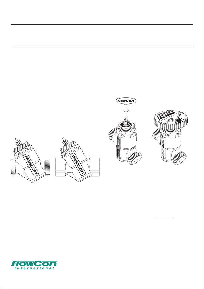
The FlowCon UniQ is available with fixed
20mm male ISO threaded connections fittable
for DN15 EuroCone according to EN215, Annex
A, i.e. figure 1.
FlowCon UniQ is similarly available with femaleby-female threaded connections DN15 or DN20,
i.e. figure 2.
Figure 1 Figure 2
For all threaded connections please clear threads
on both valve and piping of debris. Sealant such
as pipe dope or teflon
thread sealings.
WHEN USING HEMP AS PIPE SEALANT,
ENSURE NO STRANDS ARE LEFT IN THE
VALVE OR PIPING.
EuroCone fittings should seal with UniQ housing
without extra sealant.
tape is recommended on
Setting the valve:
The desired flow rate is chosen by adjusting the
valve (turned from setting 1.0 and up), with a
special designed key for a rough setting of the
valve (figure 3) or a large FlowCon adjustment
wheel for a micrometer setting (figure 4). There is
only one correct way to place the wheel on the
valve. Make sure there is no gap between the
wheel and the FlowCon UniQ.
Figure 3 Figure 4
The key or wheel are used to adjust the scale
on the top of the valve. Position is defined by
a “dot” marked on the edge of the housing top.
Once the correct flow rate has been selected,
the actuator can be applied. Please see specific installation instruction for selected actuator.
It is important to adjust the valve according to the setting needed BEFORE pressure
is applied to the system.
1B95038 01/2014
Denmark Dubai USA Brasil Singapore www.owcon.com
- 1 -
FlowCon International assumes no responsibility for mistakes, if any, in any printed material.
Page 2
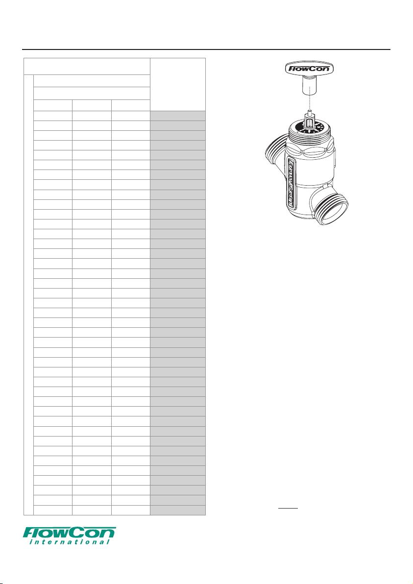
FlowCon UniQ
FlowCon UniQ
15/20mm · 1/2” / 3/4”
1
10
-200 kPaD · 1.51-29 psid
l/sec l/hr GPM
0.0056 20.3 0.089 1.0
0.0100 36.0 0.158 1.1
0.0157 56.7 0.249 1.2
0.0223 80.1 0.353 1.3
0.0291 105 0.461 1.4
0.0360 129 0.570 1.5
0.0426 153 0.675 1.6
0.0489 176 0.775 1.7
0.0549 198 0.869 1.8
0.0604 218 0.957 1.9
0.0657 237 1.041 2.0
0.0708 255 1.121 2.1
0.0757 273 1.199 2.2
0.0806 290 1.277 2.3
0.0856 308 1.356 2.4
0.0908 327 1.439 2.5
0.0963 347 1.526 2.6
0.1022 368 1.618 2.7
0.1084 390 1.716 2.8
0.1149 414 1.820 2.9
0.1218 439 1.930 3.0
Nominal ow rate
0.1291 465 2.044 3.1
0.1365 491 2.162 3.2
0.1440 518 2.281 3.3
0.1515 546 2.400 3.4
0.1589 572 2.516 3.5
0.1658 597 2.627 3.6
0.1723 620 2.730 3.7
0.1782 642 2.823 3.8
0.1833 660 2.903 3.9
0.1874 675 2.969 4.0
0.1907 686 3.020 4.1
0.1929 695 3.056 4.2
0.1943 699 3.078 4.3
0.1947 701 3.084 4.4
0.1951 702 3.091 4.5
0.1952 703 3.092 4.6
0.1958 705 3.102 4.7
0.1976 711 3.130 4.8
0.2015 725 3.192 4.9
0.2086 751 3.305 5.0
Setting
TEMPERATURE CONTROL
AND AUTOMATIC BALANCING VALVE
Figure 5
Accuracy: Greatest of either ±10% of controlled ow rate or
±5% of maximum ow rate.
Note 1: Min. ΔP=10 x √setting
1B95038 01/2014
Denmark Dubai USA Brasil Singapore www.owcon.com
- 2 -
FlowCon International assumes no responsibility for mistakes, if any, in any printed material.
Page 3

FlowCon UniQ
Assembly drawing FlowCon UniQ:
A: FlowCon UniQ valve
(here with 20mm male (ISO) suitable for
DN15 EuroCone)
B: Adjustment key
C: Adjustment wheel
D: EuroCone union end connections
(here 15mm male)
E: Actuator (here EV.0.2).
B
A
TEMPERATURE CONTROL
AND AUTOMATIC BALANCING VALVE
E
C
D
General.
It is recommended flushing the system before
installing the FlowCon UniQ. Please make
sure the entire pipeline is flushed. If it is not
D
Warranty obligation.
Failure to abide by all recommendations as per
this installation and operation instruction will void
warranty.
Figure 6
possible to flush the system unless the FlowCon
UniQ is installed, please make sure to adjust
For latest updates please see www.flowcon.com
the setting to 5.0. Water must always be
suitable treated, clean and free of debris. It is
recommended that a strainer be installed prior to
the valve body to prevent damage or blockage
due to debris. Ensure that the valve is not in the
fully closed position when filling the system with
water.
1B95038 01/2014
Denmark Dubai USA Brasil Singapore www.owcon.com
- 3 -
FlowCon International assumes no responsibility for mistakes, if any, in any printed material.
Page 4

FlowCon UniQ
TEMPERATURE CONTROL
AND AUTOMATIC BALANCING VALVE
1B95038 01/2014
Denmark Dubai USA Brasil Singapore www.owcon.com
- 4 -
FlowCon International assumes no responsibility for mistakes, if any, in any printed material.
 Loading...