

FlowCon SM.3.0, SM.3.1, SM.3.2, SM.4.2, SM.4.3 Installation And Operation Instructions Manual
...Page 1
FlowCon SM 50-150mm DYNAMIC SELF BALANCING
CONTROL VALVE
INSTALLATION AND OPERATION INSTRUCTION
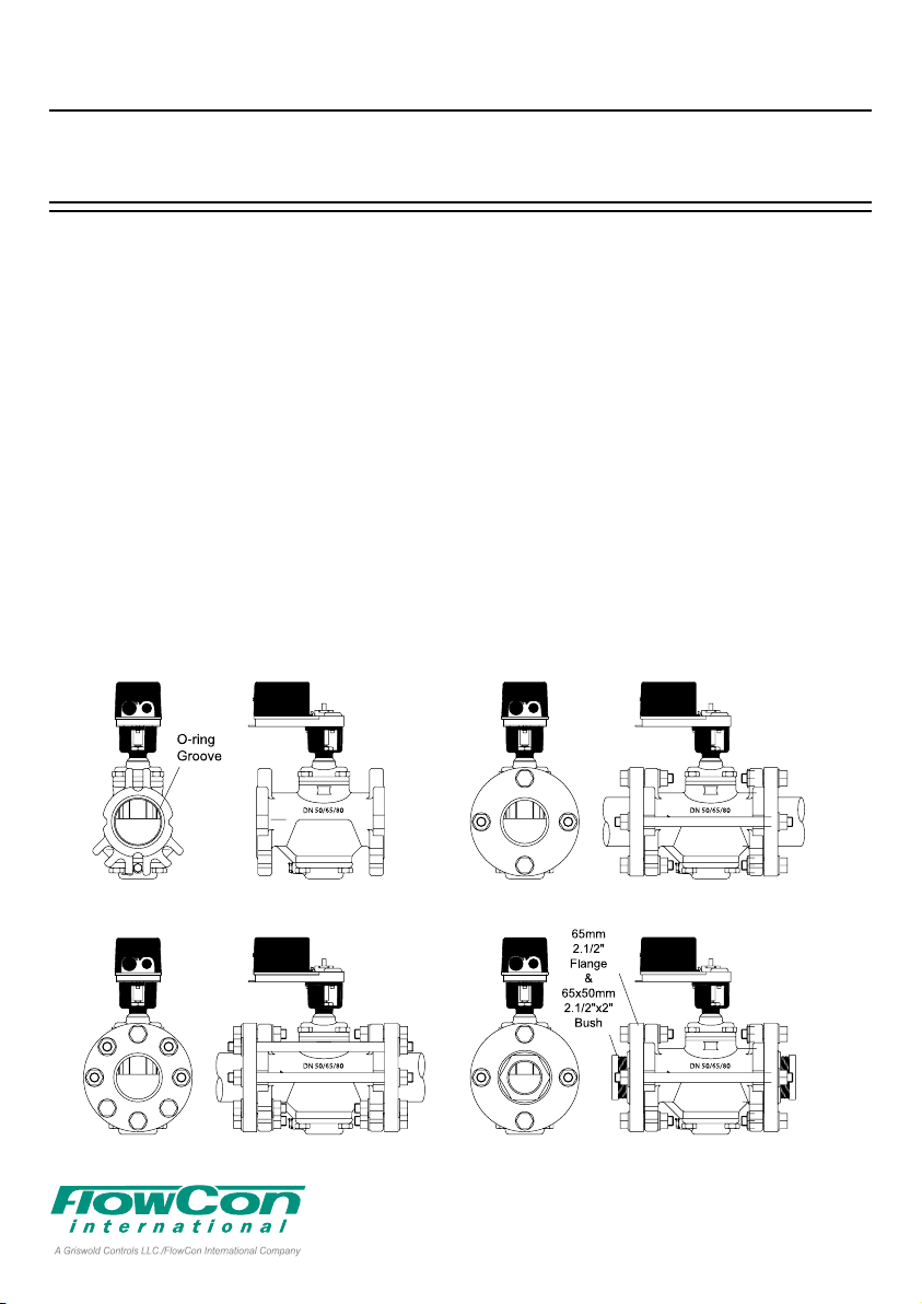
FlowCon SM 50-150mm, 2”-6”
Install the FlowCon SM valve either in the
supply or return pipe work for the unit. It is
recommended that a strainer be installed
prior to the valve body to prevent damage or
blockage due to debris. INSTALL THE VALVE
HOUSING WITH THE FLOW DIRECTIONAL
ARROW POINTING IN THE CORRECT
DIRECTION.
The valve body is available for double flange
connections, i.e figure 1.
O-rings are supplied with the valve body and
are used to seal the connections. Pls. make
sure these are in place in the o-ring grooves
in the inlet and outlet of the valve body, when
installing the housing.
recommended to grease the o-rings with
It is
a silicone grease before installation.
IMPORTANT: Never use mineral oil or petrol
based grease or oil on the o-rings.
Valve bodies are as standard supplied with
pressure/temperature fittings (p/t plugs).
Before finger mounting the p/t plugs in the
body tappings, please seal the threads of the
p/t plugs (DO NOT OVER TIGHTEN).
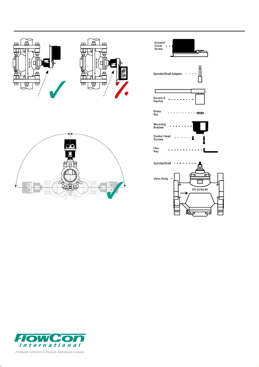
Fitting and orientation
of the actuator
Pls. install the valve so that the actuator
is located upwards and not lower than the
horizontal line to prevent condensation into
the electronics (pls. see figure 2 next page).
Figure 1
1A95105 - 08/2016
Denmark Dubai USA Singapore www.owcon.com
FlowCon International assumes no responsibility
- 1 -
for mistakes, if any, in any printed material.
Page 2
FlowCon SM 50-150mm DYNAMIC SELF BALANCING
Max 90º Max 90º
CONTROL VALVE
CORRECT:
Orientation of actuator with
the circuit bord above the
valve spindle
Max 90º Max 90º
Figure 2
WRONG:
Condensate can drip off the
shaft adapter into this support of the mounting bracket,
gathering until it leaks into the
actuator.
Valve and actuator mounting components and
tool are shown in figure 3.
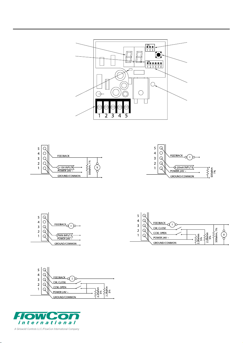
Actuator wiring and programming
Remove the actuator cover by loosening the
cover screw. Figure 4 illustrates the actuator
circuit board layout and all relevant components when programming your actuator. Set
the maximum flow DIP switches (refer to tables
on page 6-8). If adjusting the DIP switch settings after power has been connected, press
the reset button to input the new setting.
Figures 5-9 illustrate the different signal requirements, i.e. Analog 2-10V, Analog 4-20
mA, Pulse Width Modulation and Digital Tri-
Figure 3
state and how to apply resistors and wires.
Connect the wiring according to the selected
input signal.
500ohm resistors (the blue ones) are supplied
for 4-20mA to 2-10V conversion and connected as illustrated in figure 5 (2-10V) or figure 6
(4-20mA).
Two 2.2Kohm resistors (the brown ones) are
supplied for special consideration for digital/
tri-state control. In this mode the actuator is
sensitive to induced electrical voltages from
other sources. To prevent such interference,
wire one 2.2Kohm resistor between pins 1 and
4 and the second 2.2Kohm resistor between
pins 1 and 3 (see figures 8 and 9).
1A95105 - 08/2016
Denmark Dubai USA Singapore www.owcon.com
FlowCon International assumes no responsibility
- 2 -
for mistakes, if any, in any printed material.
Page 3
FlowCon SM 50-150mm DYNAMIC SELF BALANCING
CONTROL VALVE
Figure 4
LED Off: Actual valve postion
Figure 5
Figure 7
Position in rotations
rotations displayed
LED On: Maximum rotation
setting displayed
(alternates every 10 sec.)
Programming and
indication LED
Wiring terminal strip
ANALOG
2-10VDC input and
2-10VDC feedback
PULSE WIDTH
MODULATION
PWM input and
4-20mA feedback
Figure 6
Figure 8
Programming DIP
switches
Reset and
recalibration button
Maximum ow DIP
switches
Manual override
clutch
(DO NOT OPERATE
WHILE POWER IS
CONNECTED)
ANALOG
4-20mA input and
4-20mA feedback
DIGITAL TRI-STATE
2-10VDC feedback
Figure 9
1A95105 - 08/2016
DIGITAL TRI-STATE
4-20mA feedback
Denmark Dubai USA Singapore www.owcon.com
- 3 -
FlowCon International assumes no responsibility
for mistakes, if any, in any printed material.
Page 4

FlowCon SM 50-150mm DYNAMIC SELF BALANCING
CONTROL VALVE
The actuator is factory preset for an analog signal. If the signal requirement must be
changed, proceed with the instruction below:
Remove power and set all
programming DIP switches
to OFF.
Apply power and within 10
seconds, press and
release the reset button.
The programming and
indication LED should
start blinking.
Turn programming DIP switch #1, #2 or #3 ON,
then OFF to select signal requirement.
Switch #1:
Digital/3-PointFloating/Tri-state.
Switch #2:
PWM Pulse
Width Modulation.
Switch #3:
Analog
2-10V or 4-20mA.
Normally Open or
Normally Closed function setting
The actuator is delivered from factory set to
Normally Closed and an analog control signal
so that a minimum signal of 2V or 4mA will
close the valve and maximum signal of 10V
or 20mA will open the valve to selected maximum flow. If changing to Normally Open, see
below:
For Normally Open set
programming switch #1 to ON.
For Normally Closed set
programming switch #1 to OFF.
Failsafe Open or
Failsafe Closed function setting
This function applies to battery back up failsafe models only. It provides power storage to
drive the actuator either open to the maximum
flow setting or fully closed in the event of a
power supply failure. As standard the actuator
is set to Failsafe Closed.
For Failsafe Open set
programming switch #2 to ON.
For Failsafe Closed set
programming switch #2 to OFF.
PWM time base resolution setting
This function applies only if the actuator has
been programmed to accept a pulse width
modulation (PWM) signal. If with PWM,
standard setting is 0.1 to 25 second/100mS
resolution.
For 0.1 to 5 second/20mS
resolution set programming
switch #3 to ON.
For 0.1 to 25 second/100mS
resolution set programming
switch #3 to OFF.
Actuator Zero and Span adjustment
Remove power from the actuator. Re-apply
power to terminal 2 and
within 10 seconds, press
and hold the reset button
until the indication LED
blinks once.
Release the reset button.
The indication LED should
remain illuminated.
1A95105 - 08/2016
Denmark Dubai USA Singapore www.owcon.com
FlowCon International assumes no responsibility
- 4 -
for mistakes, if any, in any printed material.
Page 5

FlowCon SM 50-150mm DYNAMIC SELF BALANCING
CONTROL VALVE
Apply the new zero voltage
to terminal 3 (any value
between 0 and 7VDC).
Press and release the reset
button to memorize this value.
The LED should blink once as
confirmation.
Apply the new maximum voltage to terminal 3
(any value between 3 and 10VDC and at least
3VDC greater than the zero value).
Press and release the
reset button to memorize
this value. The indication
LED should blink once as
confirmation and then
cease to be illuminated.
The actuator will now operate with the new
zero value and span.
FAILURE: If the LED provides 3 sequences of
4 blinks, the zero and span programming was
unsuccessful. This may occur if the difference
between the zero and maximum voltages was
not equal or grater than 3VDC.
NOTE: The feedback signal will always be 420mA or 2-10V and independent of the zero
and span adjustment.
Circuit board diode
over-torque warning signal
Continual blinking indicates that the actuator
torque output limit has been exceeded.
This may have been caused by debris in the
valve internals. Disconnect power and manually operate the valve to clear the debris.
Re-apply power. The actuator will automatically recalibrate and reset. If the problem reoccurs, remove the valve body and check for
debris.
Manual over-ride operation
Remove actuator cover and DISCONNECT
POWER. Failure to disconnect power may
cause damage to the actuator gears. Fit the
manual over-ride key (FlowCon No. ACC0001)
onto the valve spindle. Press the clutch. Rotate
the manual over-ride key to open or close the
valve as required.
Figure 10
General
Water must always be suitable treated, clean
and free of debris. It is recommended that a
strainer be installed prior to the valve body to
prevent damage or blockage due to debris.
Ensure that the valve is not in the fully closed
position when filling the system with water.
Further, it is recommended not to exceed
maximum differential pressure control range.
Warranty obligation
Failure to abide by all recommendations as
per this installation and operation instruction
will void warranty.
For latest updates please see www.flowcon.com
1A95105 - 08/2016
Denmark Dubai USA Singapore www.owcon.com
FlowCon International assumes no responsibility
- 5 -
for mistakes, if any, in any printed material.
Page 6

FlowCon SM 50-150mm DYNAMIC SELF BALANCING
CONTROL VALVE
Maximum ow rate limitation DIP switch settings, SM3
Maximum Flow Rate
30-600 kPaD
4.5-87 psid
SM.3.0 SM.3.1 SM.3.2
l/sec l/hr GPM l/sec l/hr GPM l/sec l/hr GPM 1 2 3 4 5 6 Rotations
1.48 5310 23.4 2.57 9240 40.7 3.55 12800 56.3 ON ON ON ON ON ON 1.0
1.58 5700 25.1 2.81 10100 44.6 3.85 13900 61.0 OFF ON ON ON ON ON 1.1
1.69 6080 26.8 3.05 11000 48.4 4.13 14900 65.6 ON OFF ON ON ON ON 1.2
1.79 6460 28.5 3.27 11800 51.9 4.41 15900 69.9 OFF OFF ON ON ON ON 1.3
1.90 6830 30.1 3.48 12500 55.3 4.67 16800 74.0 ON ON OFF ON ON ON 1.4
2.00 7190 31.7 3.69 13300 58.5 4.92 17700 78.0 OFF ON OFF ON ON ON 1.5
2.09 7540 33.2 3.88 14000 61.5 5.16 18600 81.8 ON OFF OFF ON ON ON 1.6
2.19 7880 34.7 4.06 14600 64.3 5.38 19400 85.4 OFF OFF OFF ON ON ON 1.7
2.28 8210 36.2 4.23 15200 67.0 5.60 20200 88.8 ON ON ON OFF ON ON 1.8
2.37 8540 37.6 4.39 15800 69.6 5.81 20900 92.1 OFF ON ON OFF ON ON 1.9
2.46 8860 39.0 4.54 16300 72.0 6.01 21600 95.3 ON OFF ON OFF ON ON 2.0
2.55 9170 40.4 4.68 16900 74.3 6.19 22300 98.0 OFF OFF ON OFF ON ON 2.1
2.63 9470 41.7 4.82 17300 76.4 6.37 22900 101 ON ON OFF OFF ON ON 2.2
2.71 9770 43.0 4.94 17800 78.4 6.54 23600 104 OFF ON OFF OFF ON ON 2.3
2.79 10100 44.3 5.06 18200 80.3 6.70 24100 106 ON OFF OFF OFF ON ON 2.4
2.87 10300 45.5 5.17 18600 82.1 6.86 24700 109 OFF OFF OFF OFF ON ON 2.5
2.94 10600 46.7 5.28 19000 83.7 7.00 25200 111 ON ON ON ON OFF ON 2.6
3.02 10900 47.9 5.37 19300 85.2 7.14 25700 113 OFF ON ON ON OFF ON 2.7
3.09 1110 0 49.0 5.47 19700 86.7 7.27 26200 11 5 ON OFF ON ON OFF ON 2.8
3.16 11400 50.1 5.55 20000 88.0 7.40 26600 117 OFF OFF ON ON OFF ON 2.9
3.22 11600 51.1 5.63 20300 89.3 7.52 27100 119 ON ON OFF ON OFF ON 3.0
3.29 11800 52.1 5.70 20500 90.5 7.63 27500 121 OFF ON OFF ON OFF ON 3.1
3.35 12100 53.1 5.77 20800 91.6 7.74 27900 123 ON OFF OFF ON OFF ON
3.41 12300 54.0 5.84 21000 92.6 7.84 28200 124 OFF OFF OFF ON OFF ON 3.3
3.46 12500 54.9 5.90 21200 93.5 7.94 28600 126 ON ON ON OFF OFF ON 3.4
3.52 12700 55.8 5.95 21400 94.4 8.03 28900 127 OFF ON ON OFF OFF ON 3.5
3.57 12900 56.6 6.01 21600 95.3 8.12 29200 129 ON OFF ON OFF OFF ON 3.6
3.62 13000 57.4 6.06 21800 96.1 8.20 29500 130 OFF OFF ON OFF OFF ON 3.7
3.67 13200 58.2 6.10 22000 96.8 8.28 29800 131 ON ON OFF OFF OFF ON 3.8
3.72 13400 58.9 6.15 22100 97.5 8.36 30100 133 OFF ON OFF OFF OFF ON 3.9
3.76 13500 59.6 6.19 22300 98.2 8.44 30400 134 ON OFF OFF OFF OFF ON 4.0
3.80 13700 60.3 6.23 22400 98.9 8.51 30600 135 OFF OFF OFF OFF OFF ON 4.1
3.84 13800 60.9 6.27 22600 100 8.58 30900 136 ON ON ON ON ON OFF 4.2
3.88 14000 61.5 6.31 22700 100 8.65 31100 137 OFF ON ON ON ON OFF 4.3
3.91 14100 62.0 6.35 22900 101 8.72 31400 138 ON OFF ON ON ON OFF 4.4
3.94 14200 62.5 6.39 23000 101 8.78 31600 139 OFF OFF ON ON ON OFF 4.5
3.97 14300 63.0 6.42 23100 102 8.85 31900 140 ON ON OFF ON ON OFF 4.6
4.00 14400 63.4 6.46 23300 102 8.91 32100 141 OFF ON OFF ON ON OFF 4.7
4.03 14500 63.9 6.50 23400 103 8.98 32300 142 ON OFF OFF ON ON OFF 4.8
4.05 14600 64.2 6.54 23500 104 9.04 32600 143 OFF OFF OFF ON ON OFF 4.9
4.07 14700 64.6 6.58 23700 104 9.11 32800 144 ON ON ON OFF ON OFF 5.0
4.09 14700 64.9 6.62 23800 105 9.18 33000 146 OFF ON ON OFF ON OFF 5.1
4.11 14800 65.1 6.67 24000 106 9.25 33300 147 ON OFF ON OFF ON OFF 5.2
4.12 14800 65.3 6.72 24200 107 9.32 33500 148 OFF OFF ON OFF ON OFF 5.3
4.13 14900 65.5 6.77 24400 107 9.39 33800 149 ON ON OFF OFF ON OFF 5.4
4.14 14900 65.7 6.82 24600 108 9.46 34100 150 OFF ON OFF OFF ON OFF 5.5
4.15 14900 65.8 6.88 24800 109 9.54 34300 151 ON OFF OFF OFF ON OFF 5.6
4.15 15000 65.9 6.94 25000 11 0 9.62 34600 153 OFF OFF OFF OFF ON OFF
4.16 15000 65.9 7.01 25200 111 9.70 34900 154 ON ON ON ON OFF OFF 5.8
4.16 15000 66.0 7.08 25500 11 2 9.79 35300 155 OFF ON ON ON OFF OFF 5.9
4.16 15000 66.0 7.15 25700 11 3 9.88 35600 157 ON OFF ON ON OFF OFF 6.0
Valve size: DN50-DN80 · 2”-3”
30-600 kPaD
4.5-87 psid
35-600 kPaD
5.1-87 psid
Maximum Flow Rate
DIP Switch Settings
Accuracy: Greatest of either ±5% of controlled ow rate or ±2% of maximum ow rate.
Stem
Rotations
From Closed
3.2
5.7
1A95105 - 08/2016
Denmark Dubai USA Singapore www.owcon.com
FlowCon International assumes no responsibility
- 6 -
for mistakes, if any, in any printed material.
Page 7

FlowCon SM 50-150mm DYNAMIC SELF BALANCING
CONTROL VALVE
Maximum ow rate limitation DIP switch settings, SM4
Maximum Flow Rate
30-600 kPaD
4.5-87 psid
SM.4.1 SM.4.2 SM.4.3
l/sec l/hr GPM l/sec l/hr GPM l/sec l/hr GPM 1 2 3 4 5 6 Rotations
3.49 12600 55.4 4.73 17000 75.0 3.68 13300 58.3 ON ON ON ON ON ON 1.0
3.88 14000 61.6 5.29 19000 83.9 4.42 15900 70.0 OFF ON ON ON ON ON 1.1
4.26 15300 67.5 5.82 21000 92.0 5.13 18500 81.3 ON OFF ON ON ON ON 1.2
4.61 16600 73.1 6.33 22800 100 5.82 21000 92.3 OFF OFF ON ON ON ON 1.3
4.94 17800 78.4 6.82 24500 108 6.50 23400 103 ON ON OFF ON ON ON 1.4
5.26 18900 83.4 7.28 26200 11 5 7.15 25700 11 3 OFF ON OFF ON ON ON 1.5
5.56 20000 88.2 7.72 27800 122 7.78 28000 123 ON OFF OFF ON ON ON 1.6
5.84 21000 92.7 8.14 29300 129 8.39 30200 133 OFF OFF OFF ON ON ON 1.7
6.11 22000 97.0 8.54 30700 135 8.99 32400 142 ON ON ON OFF ON ON 1.8
6.36 22900 101 8.91 32100 141 9.56 34400 152 OFF ON ON OFF ON ON 1.9
6.60 23800 105 9.27 33400 147 10.1 36400 160 ON OFF ON OFF ON ON 2.0
6.82 24600 108 9.61 34600 152 10.7 38400 169 OFF OFF ON OFF ON ON 2.1
7.03 25300 112 9.93 35700 157 11.2 40200 177 ON ON OFF OFF ON ON 2.2
7.23 26000 115 10.2 36800 162 11.7 42100 185 OFF ON OFF OFF ON ON 2.3
7.41 26700 117 10.5 37800 167 12.2 43800 193 ON OFF OFF OFF ON ON 2.4
7.58 27300 120 10.8 38800 171 12.6 45500 200 OFF OFF OFF OFF ON ON 2.5
7.73 27800 123 11.0 39700 175 13.1 47100 207 ON ON ON ON OFF ON 2.6
7.88 28400 125 11.3 40500 179 13.5 48700 214 OFF ON ON ON OFF ON 2.7
8.01 28800 127 11.5 41300 182 13.9 50200 221 ON OFF ON ON OFF ON 2.8
8.14 29300 129 11.7 42000 185 14.3 51600 227 OFF OFF ON ON OFF ON 2.9
8.25 29700 131 11.9 42700 188 14.7 53000 233 ON ON OFF ON OFF ON 3.0
8.35 30100 132 12.0 43400 191 15.1 54300 239 OFF ON OFF ON OFF ON 3.1
8.45 30400 134 12.2 43900 194 15.4 55600 245 ON OFF
8.53 30700 135 12.4 44500 196 15.8 56800 250 OFF OFF OFF ON OFF ON 3.3
8.61 31000 137 12.5 45000 198 16.1 58000 255 ON ON ON OFF OFF ON 3.4
8.68 31300 138 12.6 45500 200 16.4 59100 260 OFF ON ON OFF OFF ON 3.5
8.74 31500 139 12.7 45900 202 16.7 60200 265 ON OFF ON OFF OFF ON 3.6
8.80 31700 140 12.9 46300 204 17.0 61200 269 OFF OFF ON OFF OFF ON 3.7
8.85 31900 140 13.0 46700 206 17.3 62100 274 ON ON OFF OFF OFF ON 3.8
8.90 32000 141 13.1 47000 207 17.5 63000 278 OFF ON OFF OFF OFF ON 3.9
8.93 32200 142 13.1 47300 208 17.8 63900 281 ON OFF OFF OFF OFF ON 4.0
8.97 32300 142 13.2 47600 210 18.0 64700 285 OFF OFF OFF OFF OFF ON 4.1
9.00 32400 143 13.3 47800 2 11 18.2 65500 218 ON ON ON ON ON OFF 4.2
9.03 32500 143 13.4 48100 212 18.4 66200 292 OFF ON ON ON ON OFF 4.3
9.05 32600 144 13.4 48300 213 18.6 66900 295 ON OFF ON ON ON OFF 4.4
9.07 32600 144 13.5 48500 214 18.8 67600 297 OFF OFF ON ON ON OFF 4.5
9.09 32700 144 13.5 48700 214 18.9 68200 300 ON ON OFF ON ON OFF 4.6
9.10 32800 144 13.6 48800 215 19.1 68700 303 OFF ON OFF ON ON OFF 4.7
9.12 32800 145 13.6 49000 216 19.2 69200 305 ON OFF OFF ON ON OFF 4.8
9.13 32900 145 13.7 49200 217 19.4 69700 307 OFF OFF OFF ON ON OFF 4.9
9.15 32900 145 13.7 49300 217 19.5 70200 309 ON ON ON OFF ON OFF 5.0
9.16 33000 145 13.7 49500 218 19.6 70600 3 11 OFF ON ON OFF ON OFF 5.1
9.18 33000 146 13.8 49600 219 19.7 70900 312 ON OFF ON OFF ON OFF 5.2
9.19 33100 146 13.8 49800 219 19.8 71300 314 OFF OFF ON OFF ON OFF 5.3
9.21 33200 146 13.9 49900 220 19.9 71600 315 ON ON OFF OFF ON OFF 5.4
9.23 33200 146 13.9 50100 221 20.0 71900 316 OFF ON OFF OFF ON OFF 5.5
9.25 33300 147 14.0 50200 221 20.0 72100 317 ON OFF OFF OFF ON OFF 5.6
9.28 33400 147 14.0 50400 222 20.1 72300 318 OFF OFF
9.31 33500 148 14.1 50600 223 20.1 72500 319 ON ON ON ON OFF OFF 5.8
9.34 33600 148 14.1 50800 224 20.2 72600 320 OFF ON ON ON OFF OFF 5.9
9.38 33800 149 14.2 51000 225 20.2 72700 320 ON OFF ON ON OFF OFF 6.0
Valve size: DN80 and DN100 · 3”-4”
35-600 kPaD
5.1-87 psid
50-600 kPaD
7.3-87 psid
Maximum Flow Rate
DIP Switch Settings
OFF ON OFF ON 3.2
OFF OFF ON OFF 5.7
Accuracy: Greatest of either ±5% of controlled ow rate or ±2% of maximum ow rate.
Stem Rotations From
Closed
1A95105 - 08/2016
Denmark Dubai USA Singapore www.owcon.com
FlowCon International assumes no responsibility
- 7 -
for mistakes, if any, in any printed material.
Page 8

FlowCon SM 50-150mm DYNAMIC SELF BALANCING
CONTROL VALVE
Maximum ow rate limitation DIP switch settings, SM5
Maximum Flow Rate
Valve size: DN125 and DN150 · 5”-6”
30-600 kPaD
4.5-87 psid
l/sec l/hr GPM l/sec l/hr GPM 1 2 3 4 5 6 Rotations
6.48 23300 103 7.10 25600 113 ON ON ON ON ON ON 1.0
7.24 26100 115 8.06 29000 128 OFF ON ON ON ON ON 1.1
7.98 28700 127 8.98 32300 142 ON OFF ON ON ON ON 1.2
8.69 31300 138 9.87 35500 157 OFF OFF ON ON ON ON 1.3
9.39 33800 149 10.7 38600 170 ON ON OFF ON ON ON 1.4
10.1 36200 160 11.6 41600 183 OFF ON OFF ON ON ON 1.5
10.7 38600 170 12.4 44500 196 ON OFF OFF ON ON ON 1.6
11.4 40900 180 13.1 47300 208 OFF OFF OFF ON ON ON 1.7
12.0 43100 190 13.9 50000 220 ON ON ON OFF ON ON 1.8
12.6 45200 199 14.6 52600 232 OFF ON ON OFF ON ON 1.9
13.1 47300 208 15.3 55100 243 ON OFF ON OFF ON ON 2.0
13.7 49300 217 16.0 57500 253 OFF OFF ON OFF ON ON 2.1
14.2 51200 226 16.6 59800 264 ON ON OFF OFF ON ON 2.2
14.7 53100 234 17.2 62100 274 OFF ON OFF OFF ON ON 2.3
15.3 54900 242 17.8 64200 283 ON OFF OFF OFF ON ON 2.4
15.7 56600 250 18.4 66300 292 OFF OFF OFF OFF ON ON 2.5
16.2 58300 257 19.0 68300 301 ON ON ON ON OFF ON 2.6
16.6 59900 264 19.5 70200 309 OFF ON ON ON OFF ON 2.7
17.1 61500 271 20.0 72100 317 ON OFF ON ON OFF ON 2.8
17.5 63000 277 20.5 73800 325 OFF OFF ON ON OFF ON 2.9
17.9 64400 284 21.0 75500 333 ON ON OFF ON OFF ON 3.0
18.3 65800 290 21.4 77200 340 OFF ON OFF ON OFF ON 3.1
18.6 67100 295 21.9 78700 347 ON OFF OFF ON OFF ON 3.2
19.0 68300 301 22.3 80200 353 OFF OFF OFF ON OFF ON 3.3
19.3 69500 306 22.7 81700 360 ON ON ON OFF OFF ON 3.4
19.6 70700 311 23.1 83100 366 OFF ON ON OFF OFF ON 3.5
19.9 71700 316 23.4 84400 372 ON OFF ON OFF OFF ON 3.6
20.2 72800 321 23.8 85700 377 OFF OFF ON OFF OFF ON 3.7
20.5 73800 325 24.1 86900 383 ON
20.7 74700 329 24.5 88100 388 OFF ON OFF OFF OFF ON 3.9
21.0 75600 333 24.8 89200 393 ON OFF OFF OFF OFF ON 4.0
21.2 76400 337 25.1 90300 398 OFF OFF OFF OFF OFF ON 4.1
21.4 77200 340 25.4 91400 403 ON ON ON ON ON OFF 4.2
21.6 77900 343 25.7 92400 407 OFF ON ON ON ON OFF 4.3
21.8 78600 346 25.9 93400 411 ON OFF ON ON ON OFF 4.4
22.0 79200 349 26.2 94300 415 OFF OFF ON ON ON OFF 4.5
22.2 79800 352 26.5 95200 420 ON ON OFF ON ON OFF 4.6
22.3 80300 354 26.7 96100 423 OFF ON OFF ON ON OFF 4.7
22.5 80800 356 26.9 97000 427 ON OFF OFF ON ON OFF 4.8
22.6 81300 358 27.2 97800 431 OFF OFF OFF ON ON OFF 4.9
22.7 81700 360 27.4 98600 435 ON ON ON OFF ON OFF 5.0
22.8 82100 362 27.6 99400 438 OFF ON ON OFF ON OFF 5.1
22.9 82400 363 27.8 100000 442 ON OFF ON OFF ON OFF 5.2
23.0 82700 364 28.1 101000 445 OFF OFF ON OFF ON OFF 5.3
23.0 83000 366 28.3 102000 448 ON ON OFF OFF ON OFF 5.4
23.1 83200 367 28.5 102000 452 OFF ON OFF OFF ON OFF 5.5
23.2 83400 367 28.7 103000 455 ON OFF OFF OFF ON OFF 5.6
23.2 83500 368 28.9 104000 458 OFF OFF OFF OFF ON OFF 5.7
23.2 83600 368 29.1 105000 461 ON ON ON ON OFF OFF 5.8
23.3 83700 369 29.3 105000 465 OFF ON ON ON OFF OFF 5.9
23.3 83800 369 29.5 106000 468 ON OFF ON ON OFF OFF 6.0
SM.5.1 SM.5.2
35-600 kPaD
5.1-87 psid
Maximum Flow Rate
DIP Switch Settings
ON OFF OFF OFF ON 3.8
Accuracy: Greatest of either ±5% of controlled ow rate or ±2% of maximum ow rate.
Stem
Rotations
From Closed
Example illustrated above:
ON-OFF-ON-ON-OFF-OFF
which gives:
(page 6)
(page 7)
- 7.15 l/sec
-
14.2 l/sec
SM.3.1
SM.4.2
SM.5.2 - 29.5 l/sec.
(rotation 6.0)
1A95105 - 08/2016
Denmark Dubai USA Singapore www.owcon.com
FlowCon International assumes no responsibility
- 8 -
for mistakes, if any, in any printed material.
 Loading...