

FlowCon SM Series, SM.1, SM.5, SM.6, SM.2 Installation And Operation Instruction Manual
...Page 1
FlowCon SM 15-250 mm (1/2”-10”)
1A95106 - 01/2019
Installation and Operation Instruction
The FlowCon SM are available in two different
double union end connected models covering five
different sizes and four different flanged models
covering nine different sizes:
FlowCon SM.1 DN15-25 (1/2”-1”)
FlowCon SM.2 DN25-40 (1”-1½”)
FlowCon SM.3 DN50-80 (2”-3”)
FlowCon SM.4 DN80-100 (3”-4”)
FlowCon SM.5 DN125-150 (5”-6”)
FlowCon SM.6 DN200-250 (8”-10”)
DN
25/32/40
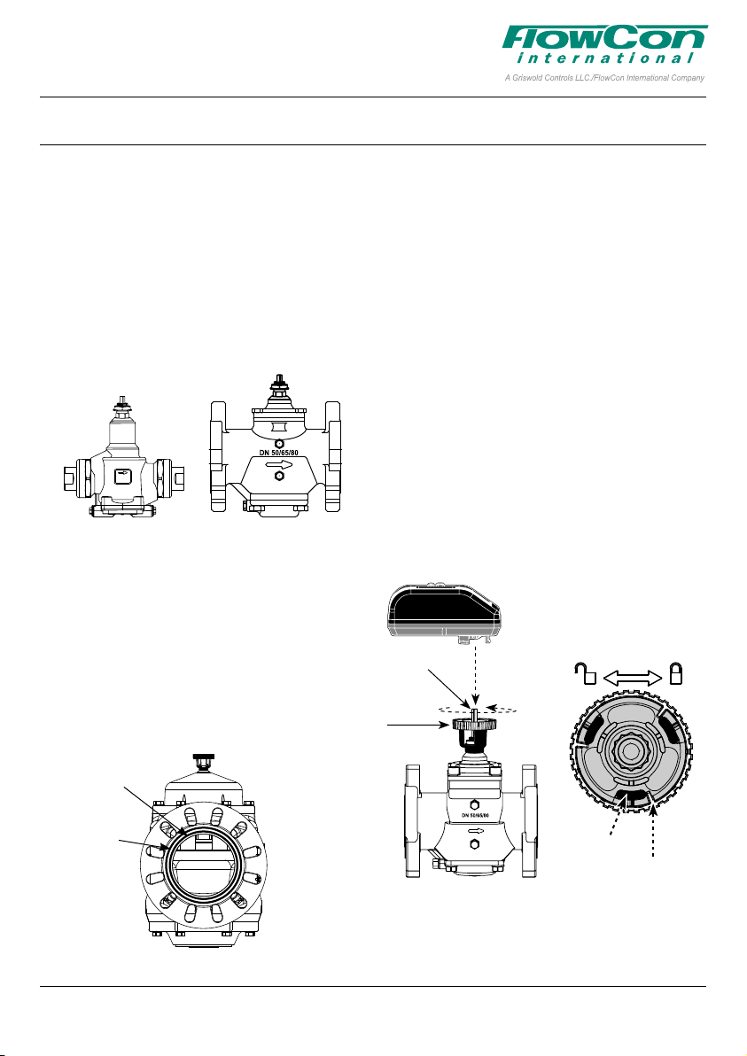
O-rings are supplied with the valve body and are
used to seal the connections. It is recommended
to grease the O-rings with silicone grease.
Please make sure these are properly placed
in the O-ring grooves on valve inlet and outlet,
before installing the housing. Please note that
FlowCon SM.6 (DN200-250 / 8”-10”) contains two
O-ring grooves. Use the inner groove for DN200 /
8” flanges and outer groove for DN250 / 10” flanges.
The actuator types FlowCon SM.0.0.0.3,
SM.0.0.0.4, SM.0.0.0.5 and SM.0.0.0.6 are elec
trical programmable actuators. SM.0.0.0.5 and
.6 are BACnet actuators and have a supplemen
tary instruction on BACnet connection and programming.
Fitting and Re-tting the actuator
It is recommended to grease the O-ring on the
spindle adaptor with silicone grease before plac
ing the spindle adaptor on the valve spindle.
Then place the actuator on the spindle adaptor
and place the three actuator “legs” into the three
holes in the mounting bracket (figure 2 and 3).
Make sure that the snap ring is clicked onto the
mounting bracket, so that the snap ring is locked
at the top of the mounting bracket, but still able to
rotate. Then finger-turn the snap ring counter
clockwise (upside view) approximately 1/6 of a
turn until its stop points touch the actuator “legs”
and the mounting is lock with a (small) click. Do
not use additional tools.
The bottom side of the
Spindle adaptor
actuator
Snap ring
-
O-ring Groove
200 mm (8”)
flanges
O-ring Groove
250 mm (10”)
flanges
Figure 1
Figure 2
“Actuator
This paper is a supplement to the FlowCon General Instruction
Latest release of any FlowCon material is available on www.owcon.com
legs”
Snap ring:
Stop points
Figure 3
Page 1 of 8
Page 2

FlowCon SM 15-250 mm (1/2”-10”)
1A95106 - 01/2019
In case the actuator will have to be removed, it
is recommended to electrically open the valve
for easier removal. Hereafter reverse the proce
dure and turn the snap ring clockwise until the
actuator is loosened and lift the actuator up.
Again, no need for additional tools.
Figure 4
Do not remove cover from actuator.
Opening cover will void warranty.
Orientation
Upside-down installation is allowed along with
the standard horizontal and vertical installation
(figure 5).
Figure 5
360º
This paper is a supplement to the FlowCon General Instruction
Latest release of any FlowCon material is available on www.owcon.com
Page 2 of 8
Page 3
FlowCon SM 15-250 mm (1/2”-10”)
1A95106 - 01/2019
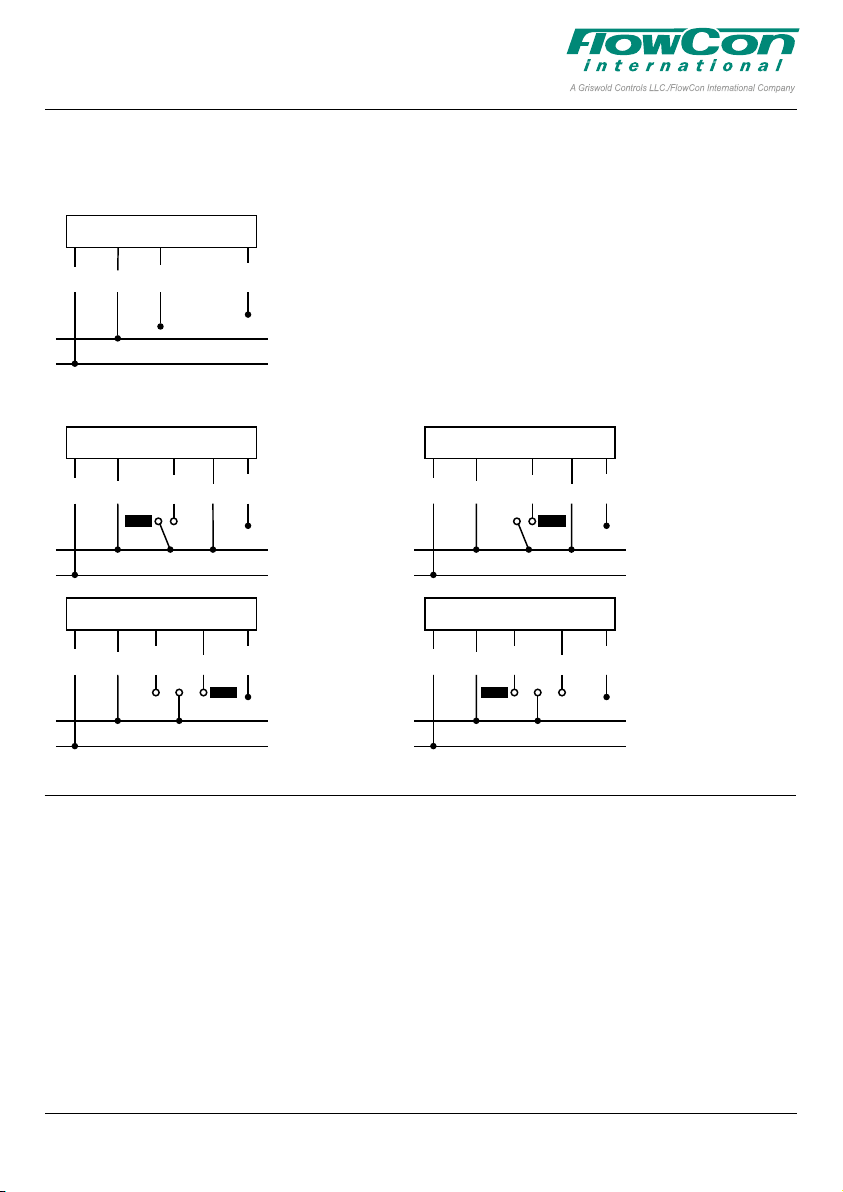
Wiring
If feedback signal is not required, leave green wire detached.
FlowCon SM (analog)
SM.0.0.0.3/4/5/6 Actuator
0(2)-10V modulating
Black
Blue
White
Input signal
0(2)-10V DC
Green
Feedback signal
0(2)-10V DC
Power 24V AC/DC
Ground/common
FlowCon SM (digital)
SM.0.0.0.3/4/5/6 Actuator
2-position, Normally Closed
Black
SM.0.0.0.3/4/5/6 Actuator
3-point floating, Normally Closed
Black
Blue
Close
Blue
Open
White
Stop
White
Open
Red
Red
Close
Green
Feedback signal
Power 24V AC/DC
Ground/common
Green
Feedback signal
Power 24V AC/DC
Ground/common
Start-Up Sequence
When power is turned on, the actuator will automatically calibrate to determine closing point of
the valve. Calibration can take up to 10 minutes
depending on the valve’s position at start-up.
During calibration actuator display will show
CAL
”. Hereafter it will procced to normal opera-
“
tion mode (according to control signal).
SM.0.0.0.3/4/5/6 Actuator
2-position, Normally Open
Black
SM.0.0.0.3/4/5/6 Actuator
3-point floating, Normally Open
Black
Blue
Open
Blue
Close
White
Stop
White
Close
Red
Red
Open
Green
Feedback signal
Power 24V AC/DC
Ground/common
Green
Feedback signal
Power 24V AC/DC
Ground/common
If no control signal is detected, flush is started if
enabled in the programming menu (enabled by
default), opening the valve to 5/6 of fully open.
FLUSH
Actuator display will show “
” until control
signal is detected.
At first start-up please enter programming menu
to set actuator settings.
This paper is a supplement to the FlowCon General Instruction
Latest release of any FlowCon material is available on www.owcon.com
Page 3 of 8
Page 4
FlowCon SM 15-250 mm (1/2”-10”)
1A95106 - 01/2019
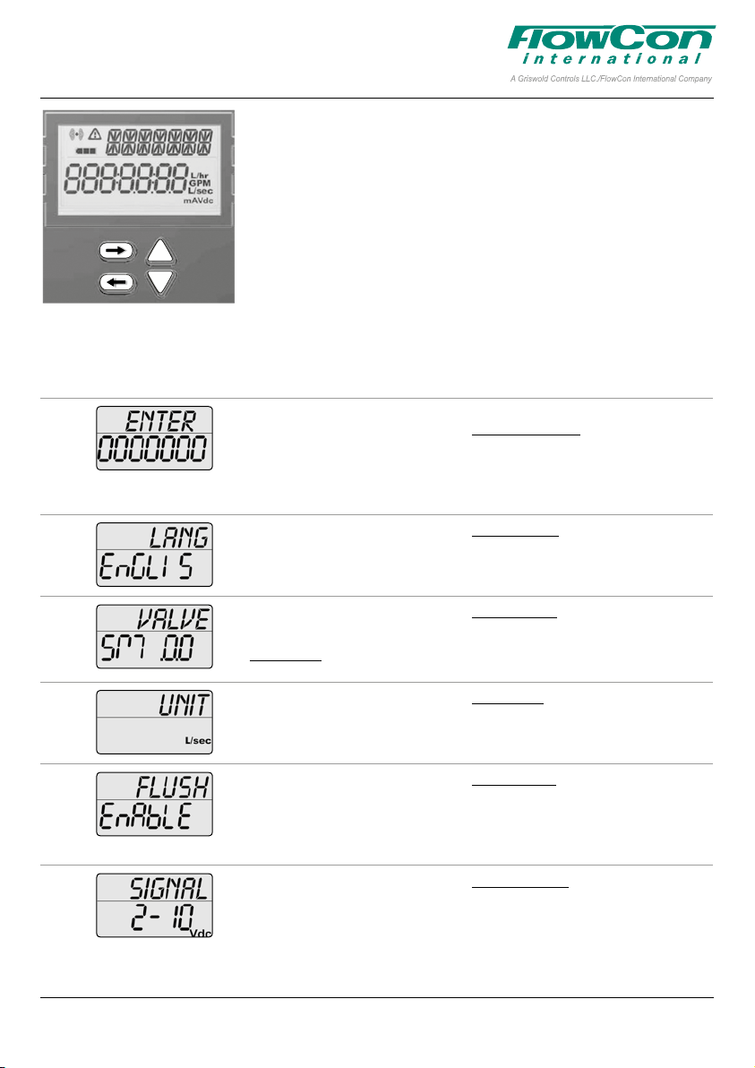
Programming Menu
The programming menu is always accessible. To enter the programming menu, simultaneously press and for 6 seconds, until
bottom line in display blinks.
To change a value, press or . For quick scroll through values
hold down
and press
or . Press to accept a value and go to next step
to go to previous step.
For fast menu exit press
and simultaneously for 6 seconds. The
actuator will automatically return to normal operation mode if no ac
tion is detected on arrow keys for 1 minute.
All values selected in the programming menu are stored in non-volatile memory.
Step Display Description Values
0 Password.
*
*scrolling top:
ENTER PASS WORD
1 Select language.
*
*scrolling top:
SELECT LANGUAG
2
*
3 Choose unit scale for flow rate.
*
4 Activate Flush mode at start-up.
*
5 Select type of control signal.
*
Select valve model onto which the
actuator is installed.
*scrolling top:
SELECT VALVE MODEL
*scrolling top:
SELECT UNIT SCALE
*scrolling top:
SELECT FLUSH MODE
*scrolling top:
SELECT CONTROL SIGNAL
Disabled by default
Password: 3569266.
Only if Enabled (in step 11).
Change one digit at a time, press
to move between digits.
At last digit, press
Default: English.
Possibility to choose other languages later
on (not currently an option).
Default: SM.0.0.
Select from the 10 available valve models.
Options: SM.1.1, SM.2.1...
Default: l/sec.
Options: l/sec or l/hr or GPM.
Default: Enable.
Options: Enable or Disable.
When no control signal (analog) is detected
at start up, flush mode is started (5/6 of fully
opened). It will be dismissed when control
signal is detected.
Default: 2-10VDC.
Options: 2-10VDC or 4-20mA or digital.
Choose:
• 2-10VDC for VDC
• 4-20mA for mA
• Digital for 2 position or 3 point floating.
to go to next step.
and
-
This paper is a supplement to the FlowCon General Instruction
Latest release of any FlowCon material is available on www.owcon.com
Page 4 of 8
Page 5

FlowCon SM 15-250 mm (1/2”-10”)
1A95106 - 01/2019
Step Display Description Values
6 Select minimum control value.
*
*scrolling top:
SET MINIMUM LIMIT
7 Select maximum control value.
*
*scrolling top:
SET MAXIMUM LIMIT
8 Select feedback signal.
*
*scrolling top:
SELECT FEEDBAC SIGNAL
9 Set the designed maximum flow.
*
10 Select direction of rotation.
*
Accuracy: Greatest of either ±5% of de
signed max. flow or ±2% of max. valve flow.
*scrolling top:
SELECT MAXIMUM FLOW
*scrolling top:
SELECT ROTAT DIRECT
Volt default: 2.
Options: from 0-7. Increment: 0.1.
mA default: 4.
Options: from 0-14. Increment: 0.2.
NA if Digital (in step 5).
Volt default: 10.
Options: from 3-10 and at least 3 VDC
greater than the selected minimum limit.
Increment: 0.1.
mA default: 20.
Options: from 6-20 and at least 6 mA
greater than the selected minimum limit.
Increment: 0.2.
NA if Digital (in step 5).
Default: AU; Automatic match of
control signal if analog.
Options: 0-10 VDC, 2-10 VDC or 4-20
mA or AU.
If Digital (in step 5) AU is not an option.
Default: Maximum setting.
-
Values depend on valve model and unit
scale chosen in step 2 and 3.
Stepping increments as per tech note.
Default: Normally Closed (NC).
Options: Normally Open (NO) or Nor
mally Closed (NC).
-
11 Select actuator mode.
*
*scrolling top:
actuator mode
12 Activation of password.
*
*scrolling top:
ACTIVAT PASS WORD
13 Select direction of rotation when Failsafe.
*
*scrolling top:
SELECT FAIL SAFE DIRECT
Default: Linear flow.
Options: Linear flow, Equal percentage,
Linear rotation or Linear signal.
For SM.1 and SM.2 only linear rotation
will apply.
Default: Disable.
Options: Enable or Disable.
If Enabled password is required to ac
cess alarm and programming menu.
Default: Closed.
Options: Open or Closed.
Only valid for SM.0.0.0.4 (failsafe
model). Failsafe direction open means
opening to max. flow
chosen in step 9.
This paper is a supplement to the FlowCon General Instruction
Latest release of any FlowCon material is available on www.owcon.com
-
Page 5 of 8
Page 6

FlowCon SM 15-250 mm (1/2”-10”)
1A95106 - 01/2019
In Operation
Display Description Values
Indicates unit scale system. l/sec or l/min or GPM.
mA or VDC.
Indicates battery level. Basic version with no battery (SM.0.0.0.3)
Alarm indicator. Blinking if actuator is still functional (warning).
Information
Failsafe version with battery (SM.0.0.0.4)
Battery level low, charging needed.
Medium battery level.
Battery charged.
Fully on if actuator is not working (critical).
CONTROL SIGNAL 2.0 VDC
FEEDBAC SIGNAL 2.0 VDC
VALVE SM. 3.1
pressur range 30-800 kpad
MAXIMUM FLOW RATE 6.580 L/SEC
OPERAT DIRECT NC
Current flow rate1.
Indicates current flow rate in
l/sec, l/hr or GPM.
Information
Control signal Indicates value of control signal. 0-10 VDC or 0-20 mA or Open/Stop/Close
Feedback signal Indicates value of feedback signal. 0-10 VDC or 0-20 mA
Valve Indicates valve model. SM.1.1, SM.2.1...
Pressure range Indicates pressure range. 32-320 kPaD, 40-320 kPaD.....
Maximum flow rate Indicates selected maximum de
Operational direction Indicates direction of rotation. NO or NC
Actuator mode Indicates control mode Linear flow, Equal percentage, Linear rotation or
Failsafe direction Indicates failsafe direction. Open or Closed
Critical Alarm Indicates alarm error code. 01, 03, 05 (without failsafe) or 06.
Note 1: The flow rate shown on the actuator display is a calculated value. Flow rates below 1.0 valve rotation is shown as indications,
illustrated with an apostrophe in front of the flow rate. If display shows “NA” the valve model has not been chosen in programming menu step 2.
signed flow rate.
ACTUAT.MODE LIN flo
FAIL SAFE DIRECT CLOSE
ERROR CODE 01
Use to go to next information line and to go
to the previous.
Depends on valve etc.
l/sec, l/hr or GPM
Linear signal
Valid for failsafe actuator models
Only if critical alarm is present.
This paper is a supplement to the FlowCon General Instruction
Latest release of any FlowCon material is available on www.owcon.com
Page 6 of 8
Page 7

FlowCon SM 15-250 mm (1/2”-10”)
1A95106 - 01/2019
Alarm Menu
To enter the alarm menu, simultaneously press and for 6 seconds. The alarm menu is
⚠
only accessible if an alarm is present (i.e. when the icon
alarm display and press
to go to previous.
is displayed). Press to go to the next
For fast menu exit press
and simultaneously for 6 seconds. The actuator will automatically
return to normal operation mode if no action is detected on arrow keys for 1 minute.
If the actuator is still functioning (= warning code 01, 04, 05 with failsafe and 07 with failsafe),
⚠
icon will blink. If the actuator is NOT functioning (=error code 01, 03, 05, 06 with failsafe
the
⚠
and 08), the
icon is fully on. Error codes will be shown in the information part of the actuator
display.
Display Description Action
Alarm.
Code
01
02
03
04
05
06
07
08
Enter password. If enabled in programming menu step 11
Icon Description Details
Valve/actuator is overtorqued. Operation is stopped. Actuator will retry operation every
FULL ON
Actuator has reached its torque limit in
BLINKING
FULL ON
BLINKING
FULL ON
BLINKING
FULL ON
BLINKING
FULL ON
the past.
Critical - over temperature. Critical: Temperature in actuator is at least 70ºC, motor
High temperature. Actuator is still functioning. Temperature in actuator is at
No Failsafe: Power supply not in range. Operation is stopped. Alarm will automatically reset
With Failsafe: Power supply not de
tected / not in range.
Control signal not detected. Operation is stopped. Alarm will automatically reset
Battery error. Battery is not properly connected. Alarm will reset when
BACnet fallback mode BACnet control value has not been updated and BAC
Disabled by default. Password: 3569266.
4 minutes. If over torque condition
disappear, error will convert to error code 02.
Actuator is functioning.
To reset the alarm simultaneously press
for 6 seconds.
operation is stopped. If temperature is decreasing,
operation will resume.
least 50ºC as limited according to tech note. If tempera
ture is decreasing, operation will resume.
when voltage is back in range.
Failsafe is activated. Alarm will automatically reset
when voltage is back in range.
when control signal is back in range.
battery is properly connected.
Only valid for failsafe actuators.
net fallback timeout has been reached. Alarm will reset
when BACnet control signal is refreshed.
Only valid for BACnet actuators.
and
-
-
This paper is a supplement to the FlowCon General Instruction
Latest release of any FlowCon material is available on www.owcon.com
Page 7 of 8
Page 8

FlowCon SM 15-250 mm (1/2”-10”)
1A95106 - 01/2019
Auto-stroke sequence
In case the valve does not operate as expected,
start the auto-stroke sequence to re-calibrate
the closing point making sure that the actuator
is able to open the valve fully. Press and
simultaneously for 6 seconds to start auto-stroke.
An auto-stroke sequence cannot be cancelled.
During auto-stroke actuator display will show
“AUTO STROKE CYCLES”. Hereafter it will proceed to
normal operation mode (according to control sig
nal). If the actuator is not able to open valve fully,
error code 01 will be displayed.
-
Manual Override
Manual override is used to temporarily set the
valve position regardless the settings and con
trol signal for the actuator. Disconnect power to
the actuator and remove the actuator from the
valve. Turn the valve spindle clockwise to close
valve and counter-clockwise to open. Re-mount
the actuator and connect power. Be aware to
protect that actuator from water while not on the
valve.
-
When manually operating the vale (actua
tor disconnected) do not use more than 10
Nm torque. Use of higher torque will void
warranty.
-
Failsafe Mode
In case of power failure, failsafe models will
move actuator to the position chosen in pro
gramming menu step 13 and show warning code
05 in the actuator display. When voltage is back
in range
⚠ will be reset.
-
This paper is a supplement to the FlowCon General Instruction
Latest release of any FlowCon material is available on www.owcon.com
FlowCon International assumes no responsibility for mistakes, if any, in any printed material.
Page 8 of 8
Page 9

FlowCon General Instruction
1B95011 - 01/2019
FlowCon General Instruction
GENERAL:
Flushing:
Water must always be suitable treated, clean
and free of debris (according to VDI 2035 recommendation).
In case of an insert-based valve, system is recommended to be flushed before the insert is installed in the valve body. A suitable flushing cap
is available. In case of a one-unit-valve, system
is recommended to be flushed before the valve
is installed. If not possible, flush the system at
maximum flow setting equal to fully open valve.
Ensure that the valve is not in the fully closed
position when filling the system with water.
It is recommended that a strainer be installed
prior to the valve body to prevent damage or
blockage due to debris.
Installation:
INSTALL THE VALVE HOUSING WITH THE
FLOW DIRECTIONAL ARROW POINTING IN
THE CORRECT DIRECTION. Valves must be
installed avoiding unnecessary pull or twist in
the valve housing.
Thread Sealing:
For threaded connections please clear threads
on both valve and piping of debris. FlowCon recommends thread sealant (Permabond A1044
or equivalent). When using Teflon tape, FlowCon
recommends 4-6 rounds of tape applied tightly
in clockwise rotation. WHEN USING HEMP AS
PIPE SEALANT, ENSURE NO
LEFT IN THE VALVE OR PIPING.
For threaded connections including sealing Oring or sealing gasket additional sealing is not
required. Please make sure the O-ring / gasket
is properly placed. After finger tightening O-ring
sealing requires 2-5 Nm torque.
EuroCone fittings will seal with FlowCon UniQ
and FlowCon Mini By-Pass without additional
sealing.
O-rings:
Any O-ring (on valve, insert or accessory) is
re-commended to be greased with silicone oil
before installation.
ral oil or petrol-based grease or oil on the Orings.
Pressure:
It is recommended to make some type of overpressure limitation to avoid the inlet pressure
never exceeds the maximum operating pres
sure. The valves shall be inspected for damage
after any overpressure condition.
IMPORTANT:
STRANDS ARE
Never use mine-
®
-
WARRANTY:
Following recommendations will prolong valve
life and give better functionality.
Failure to abide by all recommendations as per
this General Instruction will void warranty.
Warranty is voided using other actuators than
supplied or recommended by FlowCon Interna
tional.
For any supplementary warranty obligations, please see the relevant product specific installation
and operation instruction.
Latest release of any FlowCon material is available on www.owcon.com
-
Page 1 of 4
Page 10

FlowCon General Instruction
1B95011 - 01/2019
FLOWCON VALVE HOUSINGS:
Install the selected valve housing as called for in
the design drawings.
FlowCon A
The housing is available with fixed female-byfemale threaded connections for all model sizes.
The A model is only available for 20 mm (3/4”)
insert and model numbers are A15.X, A20.X and
A25.I.K.
FlowCon AB
The housing is similarly available with fixed
female-by-female threaded connections for all
model sizes. The AB model is available for 20
mm (3/4”) insert (model numbers are AB15.X,
AB20.X and AB25.I.K), 40 mm (1 1/2”) insert
(model numbers are AB25.X and AB32.X) and
50 mm (2”) insert (model numbers are AB40.X
and AB50.X). P/t plugs with collar.
FlowCon ABV
The housing is available with double union end
connections for all model sizes. The ABV model
is available for 20 mm (3/4”) insert (model num
ber ABV1) and 40 mm (1 1/2”) insert (model
number ABV2). P/t plugs with collar.
FlowCon AHU
The valve is available for double flanged connec
tions for all model sizes. P/t plugs without collar.
-
-
FlowCon K
The valve is available with fixed female-by-fe
male threaded connections for all model sizes.
P/t plugs with collar.
FlowCon Partner Ball
The valve is available with fixed female-by-fe
male threaded connections for all model sizes.
P/t plugs without collar.
FlowCon Partner Globe
The valve is available for double flanged connections for all model sizes. P/t plugs without collar.
FlowCon PIM-DP
The valve is available for double flanged connections for all model sizes. P/t plugs without collar.
FlowCon QuickDisc
®
The valve is available with fixed female-by-female threaded connections for all model sizes.
P/t plugs without collar.
FlowCon SM
The valve is available with double union end
connections or double flange connections de
pending on size. P/t plugs without collar.
FlowCon Unimizer
®
The valve is available with double union end
connections or double flange connections de
pending on size. P/t plugs without collar.
FlowCon FIT
The valve is available with double union end
connections or double flange connections de
-
pending on size. P/t plugs without collar.
FlowCon UniQ
The valve is available with fixed female-by-female
threaded connections. Further, it is available
with fixed 20 mm male ISO threaded connec
®
tions suitable for DN15 EuroCone according
FlowCon Green.3
The valve is available with fixed female-by-fe-
to EN215. The UniQ® model numbers are
U.0.XX.1.I, U.0.XX.2.I and U.0.XX.3.I.
male threaded connections for all model sizes.
P/t plugs with collar.
FlowCon Wafer
The wafer is available for double flanged connec-
FlowCon Intelligent Meter
The valve is available for double flanged connec
tions for all model sizes. P/t plugs without collar.
-
tions for all model sizes. P/t plugs without collar.
Latest release of any FlowCon material is available on www.owcon.com
-
Page 2 of 4
Page 11

FlowCon General Instruction
1B95011 - 01/2019
Valve Threaded Ends:
Thread standard is either ISO 228, which is a
straight metric thread (compatible with BS-2779)
or NPT threading standard, depending on the
product number ordered.
Valve Flanged Ends:
Flange ends are compatible with DIN steel flang
es PN10, PN16, PN25 and/or PN40 according to
EN1092-1 or ANSI steel flanges class 150 and/
or 300 according to ASME B16.5. depending on
product ordered.
Flanges are not supplied by FlowCon.
FLOWCON VALVE ACCESSORIES:
Two different types of pressure/temperature fittings (p/t plugs) are available upon request for
valves with body tappings, i.e. p/t plugs with
out collar and p/t plugs with collar. Suitable
p/t plug choice will depend on the valve. Alterna
tive to p/t plugs, the valve body can be ordered
with plugs for the body tappings. Extended p/t
plugs (without collar) are standard included with
FlowCon AHU and FlowCon Wafer.
Before finger mounting p/t plugs without collar in
the body tappings (DO NOT OVER TIGHTEN),
please seal the threads of the p/t plugs. Thread
sealing is described elsewhere in this General
Instruction. P/t plugs with collar as well as plugs
are sealed by a gasket. After finger mounting,
gasket sealing requires 1-3 Nm torque.
-
-
Capillary tubes are not to be damaged.
Therefore, do not force the tube to compress or
bend with a bending radius below 20 mm (3/4”).
Capillary tube for inserts (ACC00110)
Capillary tube is supplied with fixed M8 fitting
and O-ring at each end. Ensure that the O-ring
is greased and correctly placed before finger
mounting the capillary tube in the FlowCon
QuickDisc
®
(DO NOT OVERTIGHTEN AS THIS
WILL DAMAGE THE O-RING). If the capillary
tube is to be mounted in a FlowCon Partner Ball
or other valve with 1/4” (ISO 7/1) tapping, a 1/4”
to M8 adaptor is available (ACC00121). Thread
sealing and O-ring lubrication are described elsewhere in this General Instruction.
Capillary tube for PIM-DP (F212)
Capillary tube is supplied with fixed angled
1/4” NPT fitting (F4039-14) at one end going
to the FlowCon Partner Globe with an adaptor
(ACC6584). The other tube end is to be as
sembled in the 1/4” NPT fitting already mounted
on the FlowCon PIM-DP. Thread sealing is de
scribed elsewhere in this General Instruction.
FLOWCON INSERTS:
Please see specific installation instruction for
selected insert (Green, EVS, E-JUST, Composite,
Stainless Steel, SDP, EDP, ADP or T-JUST) regarding valve housing match, installation and
setting.
Threaded union end connections (male or fe
male) for union end connected valves must have
-
FLOWCON ACTUATORS:
the union nuts and the end connections should
be removed for installation.
Please see specific installation instruction for selected actuator (EV, FT, FN, FH, SM, BB or T)
Soldered union end connections (sweat) for
union ned connected valves must have the END
CONNECTIONS REMOVED FROM THE HOU-
regarding product fitting, mounting position and
wiring. For product match please read FlowCon
Actuator Matrix.
SING BEFORE SOLDERING. THIS ENSURES
THAT THE O-RINGS AND INTERNAL PARTS
ARE NOT DAMAGED BY HEAT.
Latest release of any FlowCon material is available on www.owcon.com
Page 3 of 4
Page 12

FlowCon General Instruction
1B95011 - 01/2019
Latest release of any FlowCon material is available on www.owcon.com
FlowCon International assumes no responsibility for mistakes, if any, in any printed material.
Page 4 of 4
 Loading...