

Page 1
FlowCon SM 15-40mm
Max 90º Max 90º
Max 90º Max 90º
INSTALLATION AND OPERATION INSTRUCTION
FlowCon SM 15-40mm, 1/2”-1 1/2”
DYNAMIC SELF BALANCING
CONTROL VALVE
Install the FlowCon SM valve either in the
supply or return pipe work for the unit. It is recommended that a strainer be installed prior to
the valve body to prevent damage or blockage
due to debris. INSTALL THE VALVE HOUSING
WITH THE FLOW DIRECTIONAL ARROW
POINTING IN THE CORRECT DIRECTION.
The valve body is available with double union
end connections. Two types of end connections are available for use with the union nut:
Threaded (male or female):
The threads on both the connection and piping should be cleaned carefully.
As these models are union end connected, the
union nuts and the end connections should be
removed for installation.
O-rings are supplied with the valve body and
are used to seal the connections. It is recommended to grease the o-rings with a silicone
grease before installation. IMPORTANT: Never
use mineral oil or petrol based grease or oil
on the o-rings. Please make sure these are
in place in the o-ring grooves in the inlet and
outlet of the valve body, when installing the
housing and REMEMBER TO TIGHTEN THE
UNIONNUTS TO ENSURE SEALING.
Valve bodies are as standard supplied with
body tappings plugged, each plug sealed with
a gasket.
Alternatively, pressure/temperature fittings
(p/t plugs) are available. Before finger mounting the p/t plugs in the body tappings, pls. seal
the threads of the p/t plugs (DO NOT OVER
TIGHTEN).
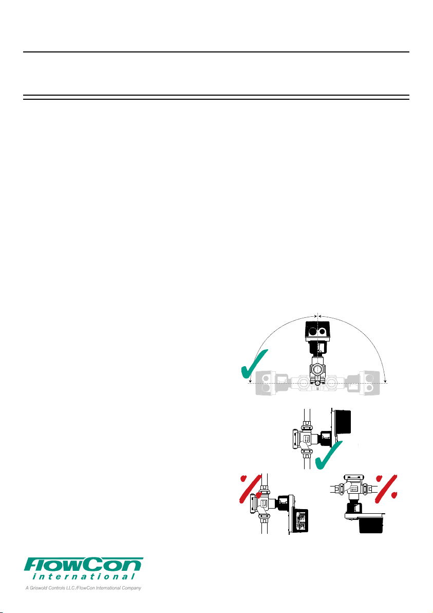
Fitting and orientation
of the actuator
Pls. install the valve so that the actuator is
located upwards and not lower than the horizontal line to prevent condensation into the
electronics (pls. see figure 1 below).
Figure 1
Max 90º Max 90º
For all threaded connections pls. clear threads
on both valve and piping of debris. Sealant such
as pipe dope or teflon tape is recommended.
WHEN USING HEMP AS PIPE SEALANT,
ENSURE NO STRANDS ARE LEFT IN THE
VALVE OR PIPING.
Soldered end (sweat):
REMOVE THE END CONNECTIONS FROM
THE HOUSING BEFORE SOLDERING. THIS
ENSURES THAT THE O-RINGS AND INTERNAL PARTS ARE NOT DAMAGED BY HEAT.
1A95100 - 08/2016
Denmark Dubai USA Singapore www.owcon.com
FlowCon International assumes no responsibility
- 1 -
for mistakes, if any, in any printed material.
Page 2
FlowCon SM 15-40mm
DYNAMIC SELF BALANCING
CONTROL VALVE
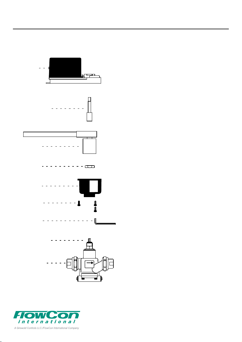
Valve and actuator mounting components and
tool are shown in figure 2.
Actuator
Cover
Screw
Spindle/
Shaft Adapter
Socket &
Rachet
Brass
Nut
Mounting
Bracket
Socket Head
Screws
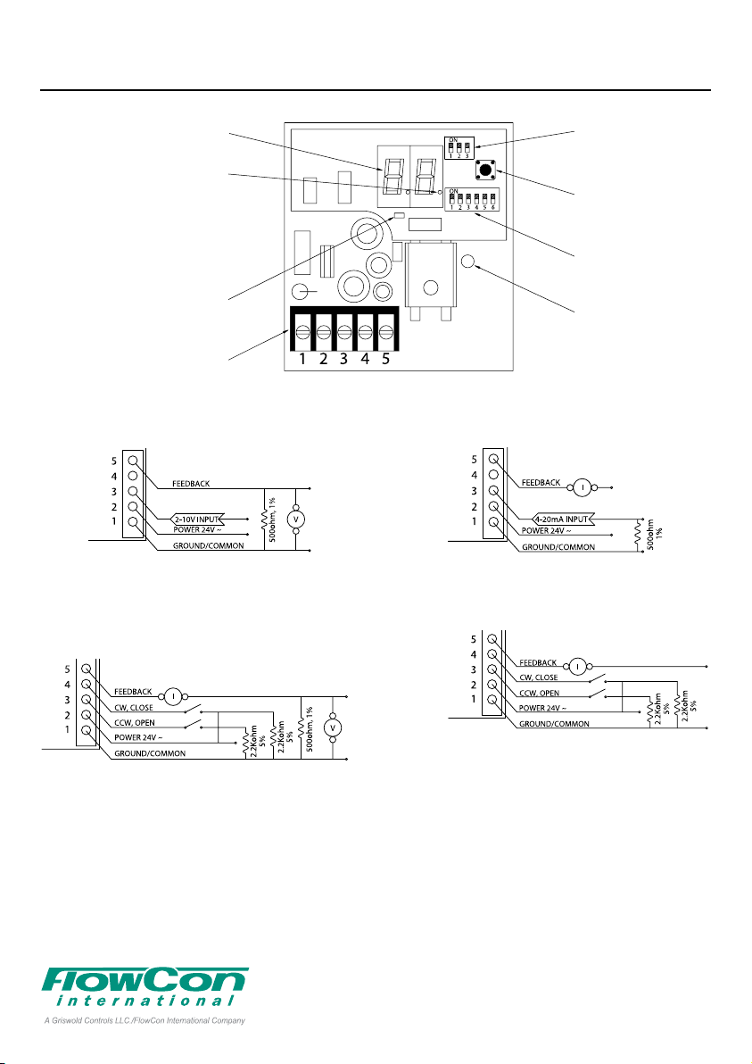
Actuator wiring and programming
Remove the actuator cover by loosening the
cover screw. Figure 3 illustrates the actuator
circuit board layout and all relevant components when programming the actuator. Set
the maximum flow DIP switches (refer to table
on page 6). If adjusting the DIP switch settings after power has been connected, press
the reset button to input the new setting.
Figures 4-8 illustrate the different signal requirements, i.e. Analog 2-10V, Analog 4-20mA
and Digital Tri-state and how to apply
resistors and wires. Connect the wiring
according to the selected input signal.
500ohm resistors (the blue ones) are supplied
for 4-20mA to 2-10V conversion and connected
as illustrated in figure 4 (2-10V) or figure 5
(4-20mA).
Two 2.2Kohm resistors (the brown ones) are
supplied for special consideration for digital/
tri-state control. In this mode the actuator is
sensitive to induced electrical voltages from
other sources. To prevent such interference,
wire one 2.2Kohm resistor between pins 1 and
4 and the second 2.2Kohm resistor between
pins 1 and 3 (see figures 6 and 7).
Hex
Key
Spindle/Shaft
Valve Body
Figure 2
1A95100 - 08/2016
DN15/20
Denmark Dubai USA Singapore www.owcon.com
FlowCon International assumes no responsibility
- 2 -
for mistakes, if any, in any printed material.
Page 3
FlowCon SM 15-40mm
Figure 3
Position in rotations
LED Off: Actual valve position
rotations displayed
LED On: Maximum rotation
setting displayed
(alternates every 10 sec.)
Programming and
indication LED
Wiring terminal strip
DYNAMIC SELF BALANCING
CONTROL VALVE
Programming DIP
switches
Reset and
recalibration button
Maximum ow DIP
switches
Manual override
clutch
(DO NOT OPERATE
WHILE POWER IS
CONNECTED)
Figure 4
Figure 6
ANALOG
2-10VDC input and
2-10VDC feedback
DIGITAL TRI-STATE
2-10VDC feedback
Figure 5
Figure 7
ANALOG
4-20mA input and
4-20mA feedback
DIGITAL TRI-STATE
4-20mA feedback
1A95100 - 08/2016
Denmark Dubai USA Singapore www.owcon.com
FlowCon International assumes no responsibility
- 3 -
for mistakes, if any, in any printed material.
Page 4

FlowCon SM 15-40mm
DYNAMIC SELF BALANCING
CONTROL VALVE
The actuator is factory preset for an analog signal. If the signal requirement must be
changed, proceed with the instruction below:
Remove power and set all
programming DIP switches
to OFF.
Apply power and within 10
seconds, press and
release the reset button.
The programming and
indication LED should
start blinking.
Turn programming DIP switch #1, #2 or #3 ON,
then OFF to select signal requirement.
Switch #1:
Digital/3-PointFloating/Tri-state.
Switch #2:
PWM Pulse
Width Modulation.
(not available on SM.0.0.0.1)
Switch #3:
Analog
2-10V or 4-20mA.
For Normally Closed set
programming switch #1 to OFF.
Failsafe Open or
Failsafe Closed function setting
This function applies to battery back up failsafe models only. It provides power storage to
drive the actuator either open to the maximum
flow setting or fully closed in the event of a
power supply failure. As standard the actuator
is set to Failsafe Closed.
For Failsafe Open set
programming switch #2 to ON.
For Failsafe Closed set
programming switch #2 to OFF.
Actuator Zero and Span adjustment
Remove power from the actuator. Re-apply
power to terminal 2 and
within 10 seconds, press
and hold the reset button
until the indication LED
blinks once.
Release the reset button.
The indication LED should
remain illuminated.
Normally Open or
Normally Closed function setting
The actuator is delivered from factory set to
Normally Closed and an analog control signal
so that a minimum signal of 2V or 4mA will
close the valve and maximum signal of 10V
or 20mA will open the valve to selected maxi-
Apply the new zero voltage
to terminal 3 (any value
between 0 and 7VDC).
Press and release the reset
button to memorize this value.
The LED should blink once as
confirmation.
mum flow. If changing to Normally Open, see
below:
For Normally Open set
programming switch #1 to ON.
1A95100 - 08/2016
Denmark Dubai USA Singapore www.owcon.com
FlowCon International assumes no responsibility
- 4 -
for mistakes, if any, in any printed material.
Page 5

FlowCon SM 15-40mm
DYNAMIC SELF BALANCING
CONTROL VALVE
Apply the new maximum voltage to terminal 3
(any value between 3 and 10VDC and at least
3VDC greater than the zero value).
Press and release the
reset button to memorize
this value. The indication
LED should blink once as
confirmation and then
cease to be illuminated.
The actuator will now operate with the new
zero value and span.
FAILURE: If the LED provides 3 sequences of
4 blinks, the zero and span programming was
unsuccessful. This may occur if the difference
between the zero and maximum voltages was
not equal or grater than 3VDC.
NOTE: The feedback signal will always be 420mA or 2-10V and independent of the zero
and span adjustment.
Circuit board diode
over-torque warning signal
Continual blinking indicates that the actuator
torque output limit has been exceeded.
This may have been caused by debris in the
valve internals. Disconnect power and manually operate the valve to clear the debris.
Re-apply power. The actuator will automatically recalibrate and reset. If the problem reoccurs, remove the valve body and check for
debris.
Manual over-ride operation
Remove actuator cover and DISCONNECT
POWER. Failure to disconnect power may
cause damage to the actuator gears. Fit the
manual over-ride key (FlowCon No. ACC0001)
onto the valve spindle. Press the clutch. Rotate
the manual over-ride key to open or close the
valve as required.
Figure 8
General
Water must always be suitable treated, clean
and free of debris. It is recommended that a
strainer be installed prior to the valve body to
prevent damage or blockage due to debris.
Ensure that the valve is not in the fully closed
position when filling the system with water.
Further, it is recommended not to exceed
maximum differential pressure control range.
Warranty obligation
Failure to abide by all recommendations as
per this installation and operation instruction
will void warranty.
For latest updates please see www.flowcon.com
1A95100 - 08/2016
Denmark Dubai USA Singapore www.owcon.com
FlowCon International assumes no responsibility
- 5 -
for mistakes, if any, in any printed material.
Page 6

FlowCon SM 15-40mm
Maximum ow rate limitation DIP switch settings
Maximum Flow Rate
DN15-DN25 · 1/2”-1” DN25-DN40 · 1”-1 1/2”
32-320 kPaD · 4.6-46 psid 40-320 kPaD · 5.8-46 psid
SM.1.1 SM.2.1
l/sec l/hr GPM l/sec l/hr GPM 1 2 3 4 5 6 Rotations
0.176 634 2.79 0.513 1850 8.14 ON ON ON ON ON ON 1.0
0.195 703 3.10 0.573 2060 9.09 OFF ON ON ON ON ON 1.1
0.214 771 3.40 0.632 2280 10.0 ON OFF ON ON ON ON 1.2
0.233 838 3.69 0.690 2480 10.9 OFF OFF ON ON ON ON 1.3
0.251 902 3.97 0.746 2690 11.8 ON ON OFF ON ON ON 1.4
0.268 964 4.25 0.802 2890 12.7 OFF ON OFF ON ON ON 1.5
0.285 1020 4.52 0.856 3080 13.6 ON OFF OFF ON ON ON 1.6
0.301 1080 4.78 0.909 3270 14.4 OFF OFF OFF ON ON ON 1.7
0.317 1140 5.03 0.961 3460 15.2 ON ON ON OFF ON ON 1.8
0.332 1200 5.27 1.01 3640 16.0 OFF ON ON OFF ON ON 1.9
0.347 1250 5.51 1.06 3820 16.8 ON OFF ON OFF ON ON 2.0
0.362 1300 5.74 1.11 4000 17.6 OFF OFF ON OFF ON ON 2.1
0.376 1350 5.96 1.16 4170 18.4 ON ON OFF OFF ON ON 2.2
0.390 1400 6.18 1.20 4330 19.1 OFF ON OFF OFF ON ON 2.3
0.403 1450 6.39 1.25 4500 19.8 ON OFF OFF OFF ON ON 2.4
0.416 1500 6.60 1.29 4660 20.5 OFF OFF OFF OFF ON ON 2.5
0.428 1540 6.79 1.34 4810 21.2 ON ON ON ON OFF ON 2.6
0.440 1590 6.98 1.38 4970 21.9 OFF ON ON ON OFF ON 2.7
0.452 1630 7.17 1.42 5120 22.5 ON OFF ON ON OFF ON 2.8
0.463 1670 7.35 1.46 5260 23.2 OFF OFF ON ON OFF ON 2.9
0.474 1710 7.52 1.50 5400 23.8 ON ON OFF ON OFF ON 3.0
0.485 1750 7.69 1.54 5540 24.4 OFF ON OFF ON OFF ON 3.1
0.495 1780 7.86 1.58 5680 25.0 ON OFF OFF ON OFF ON 3.2
0.505 1820 8.01 1.61 5810 25.6 OFF OFF OFF ON OFF ON 3.3
0.515 1850 8.17 1.65 5940 26.2 ON ON ON OFF OFF ON 3.4
0.524 1890 8.31 1.69 6070 26.7 OFF ON ON OFF OFF ON 3.5
0.533 1920 8.46 1.72 6190 27.3 ON OFF ON OFF OFF ON 3.6
0.542 1950 8.60 1.75 6310 27.8 OFF OFF
0.550 1980 8.73 1.79 6430 28.3 ON ON OFF OFF OFF ON 3.8
0.559 2010 8.86 1.82 6550 28.8 OFF ON OFF OFF OFF ON 3.9
0.567 2040 8.99 1.85 6660 29.3 ON OFF OFF OFF OFF ON 4.0
0.574 2070 9.11 1.88 6770 29.8 OFF OFF OFF OFF OFF ON 4.1
0.582 2090 9.23 1.91 6870 30.3 ON ON ON ON ON OFF 4.2
0.589 2120 9.34 1.94 6980 30.7 OFF ON ON ON ON OFF 4.3
0.596 2150 9.45 1.97 7080 31.2 ON OFF ON ON ON OFF 4.4
0.603 2170 9.56 1.99 7180 31.6 OFF OFF ON ON ON OFF 4.5
0.609 2190 9.66 2.02 7280 32.1 ON ON OFF ON ON OFF 4.6
0.616 2220 9.76 2.05 7370 32.5 OFF ON OFF ON ON OFF 4.7
0.622 2240 9.86 2.07 7460 32.9 ON OFF OFF ON ON OFF 4.8
0.628 2260 9.96 2.10 7550 33.3 OFF OFF OFF ON ON OFF 4.9
0.634 2280 10.0 2.12 7640 33.7 ON ON ON OFF ON OFF 5.0
0.639 2300 10.1 2.15 7730 34.0 OFF ON ON OFF ON OFF 5.1
0.645 2320 10.2 2.17 7810 34.4 ON OFF ON OFF ON OFF 5.2
0.650 2340 10.3 2.19 7890 34.8 OFF OFF ON OFF ON OFF 5.3
0.655 2360 10.4 2.21 7970 35.1 ON ON OFF OFF ON OFF 5.4
0.661 2380 10.5 2.24 8050 35.5 OFF ON OFF OFF ON OFF 5.5
0.666 2400 10.6 2.26 8130 35.8 ON OFF OFF OFF ON OFF 5.6
0.671 2410 10.6 2.28 8200 36.1 OFF OFF OFF OFF ON OFF 5.7
0.676 2430 10.7 2.30 8280 36.5 ON ON ON ON OFF OFF 5.8
0.680 2450 10.8 2.32 8350 36.8 OFF ON ON ON OFF OFF 5.9
0.685 2470 10.9 2.34 8420 37.1 ON OFF ON ON OFF OFF 6.0
Maximum Flow Rate
DIP Switch Settings
ON OFF OFF ON 3.7
Rotations
From Closed
DYNAMIC SELF BALANCING
CONTROL VALVE
Stem
Example illustrated above:
ON-OFF-ON-ON-OFF-OFF
which gives a max ow of:
SM.1.1 - 0.685l/sec and
SM.2.1 - 2.34l/sec
(rotation 6.0).
Accuracy: Greatest of either
±5% of controlled ow rate or
±2% of maximum ow rate.
1A95100 - 08/2016
Denmark Dubai USA Singapore www.owcon.com
FlowCon International assumes no responsibility
- 6 -
for mistakes, if any, in any printed material.
Page 7

FlowCon SM 15-40mm
Assembly drawing
FlowCon SM
A: Valve housing
B: Actuator
C1: P/t plug (2 pcs.)
C2: Plug and gasket (2 of each)
D: Union end connections.
B
Figure 9
DYNAMIC SELF BALANCING
CONTROL VALVE
D
A
D
C1 C1C2C2
1A95100 - 08/2016
Denmark Dubai USA Singapore www.owcon.com
FlowCon International assumes no responsibility
- 7 -
for mistakes, if any, in any printed material.
Page 8

FlowCon SM 15-40mm
Own Notes:
DYNAMIC SELF BALANCING
CONTROL VALVE
1A95100 - 08/2016
Denmark Dubai USA Singapore www.owcon.com
FlowCon International assumes no responsibility
- 8 -
for mistakes, if any, in any printed material.
 Loading...