

Page 1
FlowCon Green.3
1B95091 - 01/2019
Installation and Operation Instruction
The FlowCon Green.3 valve is female/female
threaded and comes in two different sizes:
• FlowCon Green.3 DN40 (1½”)
• FlowCon Green.3 DN50 (2”)
IMPORTANT: Do not disassemble.
FlowCon Greeen.3 is built as a complete valve
and only trained FlowCon personnel can per
form repair. Unauthorized disassembly may result in calibration defects or damaged part and
will void warranty.
The
-
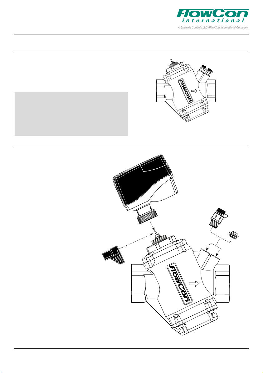
General Assembly Drawing
FlowCon Green.3
A: Valve housing
B: FlowCon actuator
C1: P/t plug (2 pcs.)
C2: Plug (2 pcs.)
D: Adjustment key.
D
Figure 1
B
C1
C2
A
This paper is a supplement to the FlowCon General Instruction
Latest release of any FlowCon material is available on www.owcon.com
Figure 2
Page 1 of 2
Page 2
FlowCon Green.3
1B95091 - 01/2019
Setting and Installation
Prior to installing the FlowCon Green.3, the system should be properly flushed. If it is not possible to flush the system before Green.3 installation, please make sure to adjust setting to 5.0
and then flush.
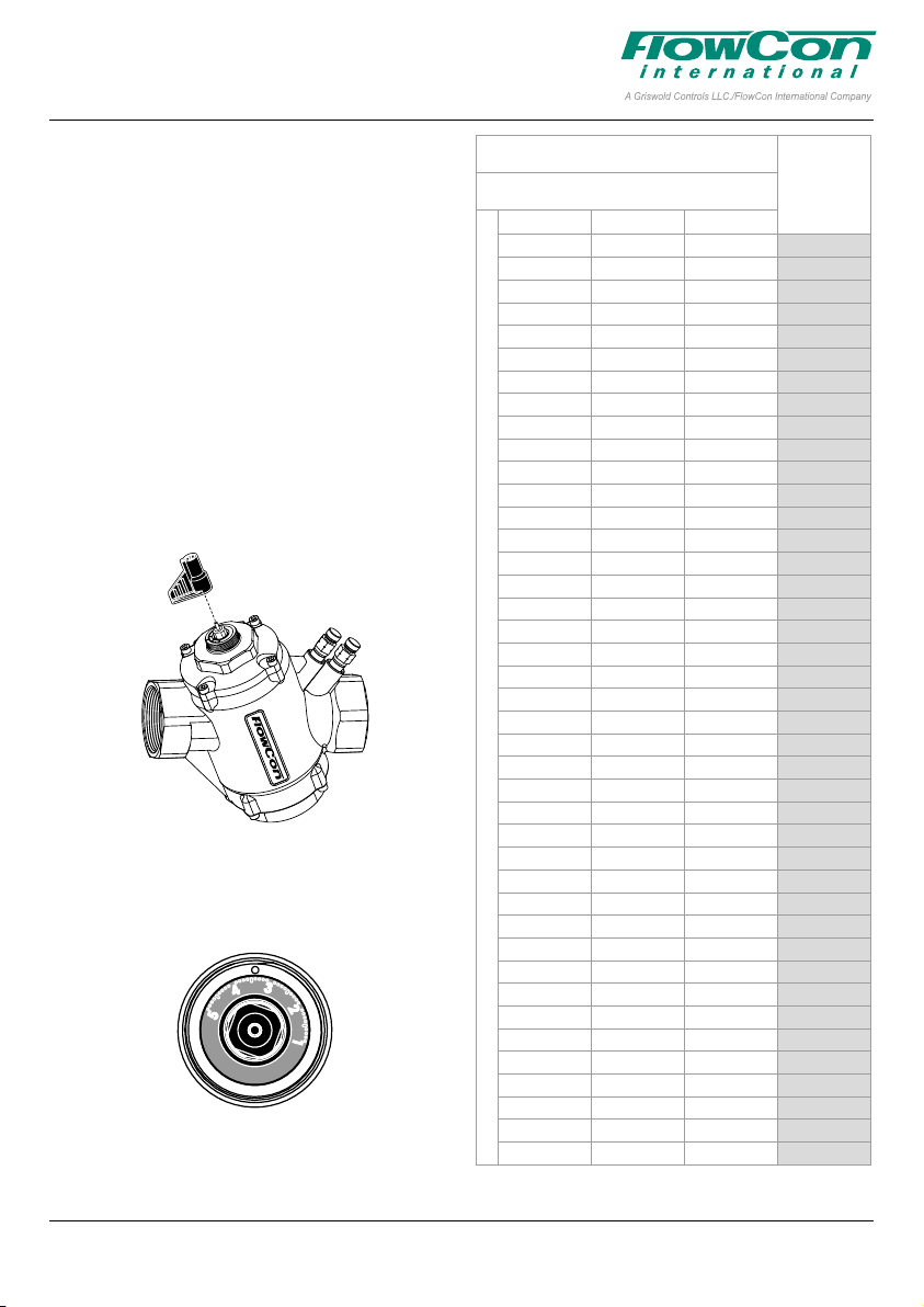
The desired flow rate is hereafter set by adjusting
the valve (turned from setting 1.0 and up) with a
special adjustment key (i.e. figure 3). Scale set
ting is located on top of the valve numbered 1
to 5 including in-between positions indicated by
dots (one dot for every 0.1 position). The specific
position is defined by an indication mark on top
of the housing. Once flow is set, the required ac
tuator may be applied. Please see specific installation instruction for selected actuator.
Figure 3
A micrometer setting of 3.4 as illustrated in figure
4 corresponds to a maximum flow rate of: 2.86
l/sec (45.4 GPM).
Figure 4
-
-
FlowCon Green.3
16-600 kPaD · 2.3-87 psid
l/sec l/hr GPM
0.528 1900 8.36 1.0
0.633 2278 10.0 1.1
0.738 2655 11.7 1.2
0.843 3033 13.3 1.3
0.947 3410 15.0 1.4
1.05 3787 16.7 1.5
1.16 4163 18.3 1.6
1.26 4537 20.0 1.7
1.36 4909 21.6 1.8
1.47 5279 23.2 1.9
1.57 5646 24.8 2.0
1.67 6011 26.4 2.1
1.77 6372 28.0 2.2
1.87 6730 29.6 2.3
1.97 7083 31.2 2.4
2.06 7432 32.7 2.5
2.16 7776 34.2 2.6
2.25 8115 35.7 2.7
2.35 8449 37.2 2.8
2.44 8777 38.6 2.9
2.53 9098 40.0 3.0
2.61 9413 41.4 3.1
Nominal flow rate
2.70 9721 42.8 3.2
2.78 10021 44.1 3.3
2.86 10314 45.4 3.4
2.94 10599 46.6 3.5
3.02 10875 47.8 3.6
3.10 111 42 49.0 3.7
3.17 11400 50.2 3.8
3.24 11649 51.3 3.9
3.30 11888 52.3 4.0
3.37 12116 53.3 4.1
3.43 12334 54.3 4.2
3.48 12540 55.2 4.3
3.54 12735 56.0 4.4
3.59 12919 56.8 4.5
3.64 13090 57.6 4.6
3.68 13249 58.3 4.7
3.72 13395 58.9 4.8
3.76 13527 59.5 4.9
3.79 13647 60.0 5.0
Accuracy: Greatest of either ±10% of controlled ow rate or
±5% of maximum ow rate.
Setting
FlowCon International assumes no responsibility for mistakes, if any, in any printed material.
This paper is a supplement to the FlowCon General Instruction
Latest release of any FlowCon material is available on www.owcon.com
Page 2 of 2
 Loading...