

Page 1

DIFFERENT PRESSURE CONTROL VALVEFlowCon DPCV
INSTALLATION AND OPERATION INSTRUCTION
FlowCon DPCV 15-50mm
Install the FlowCon DPCV in the return pipework of the riser with connection to the supply
pipework of the riser through the capillary tube
as called for in the design drawings. It is recom
mended that a strainer be installed prior to the
inlet of the capillary tube to prevent damage or
blockage due to debris. INSTALL THE VALVE
HOUSING WITH THE FLOW DIRECTIONAL
TRIANGLE POINTING IN THE CORRECT DI
RECTION.
Figure 1
The valve body is available with female threaded
end connections. The thread standard is EN
10226-1, which is a straight metric thread. Please
clear threads on both valve and piping of debris. Sealant such as pipe dope or Teflon tape is
recommended. WHEN USING HEMP AS PIPE
SEALANT, ENSURE NO STRANDS ARE LEFT
IN THE VALVE OR PIPING.
For each end of the capillary tube start by mount
ing the big nut with the gasket () in the valve
and proceed as shown in figure 2. Pull the small
nut () onto the copper tube () with the thread
toward the end of the tube, and then push the
cutting ring () onto the tube as far as possible.
Push the copper tube into the hole of the big nut
and screw the small nut into the big nut with a
wrench using 12-15Nm.
Figure 2
When the DPCV is installed with the capillary
tube in place and the system is operational,
please vent the capillary tube as shown in figure
3. Open the highest elevated screw byturning it
counter-clockwise max. 2 rotations until water
runs constantly from it, and then close it again.
Figure 3
The capillary tube is available with ¼” straight
male end connections with gaskets for sealing.
One end is mounted on the upper part of the
DPCV instead of the black plastic
plug. The other end is mounted at the inlet of the
riser fx. in a FlowCon ABS.
1H95000 - 04/2016
Denmark Dubai USA Singapore www.owcon.com
As standard, the valve body is supplied with
plugs in the body tappings. Each plug is sealed
FlowCon International assumes no responsibility
- 1 -
for mistakes, if any, in any printed material.
Page 2
with a gasket. Alternative to plugs, pressure/temperature fittings (p/t plugs) are available
upon request for the DPCV valve. Before finger
mounting the p/t plugs in the tappings please
seal the threads of the p/t plugs (DO NOT OVER
TIGHTEN).
Pump pressure
Please do not use the FlowCon DPCV in sys
with pump pressures higher than 210kPaD.
tems
DIFFERENT PRESSURE CONTROL VALVEFlowCon DPCV
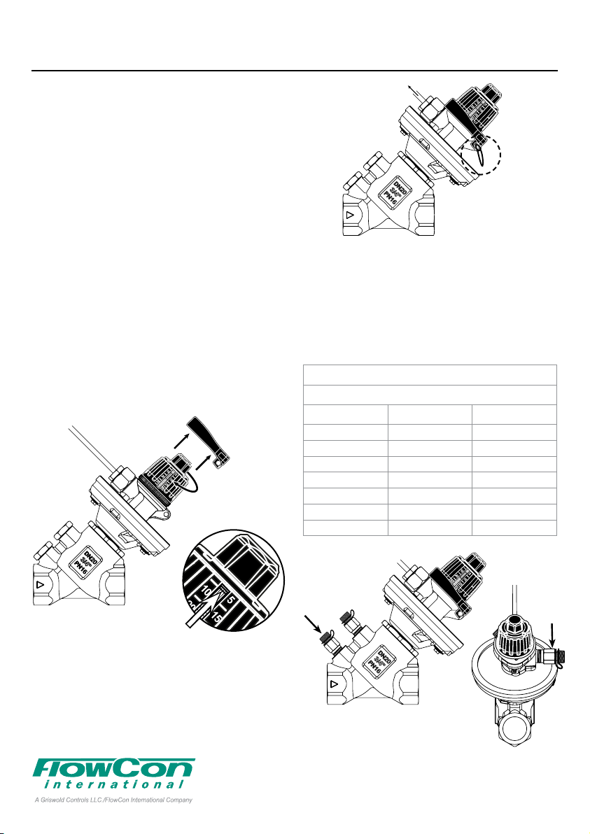
Figure 5
Setting the DPCV
To change the setting, please remove the black
lock ring () and turn the black top part by hand
() as shown in figure 4 (do not use more than
1 Nm force). Turn the black top part clockwise to
increase and counter-clockwise to decrease the
setting. The setting can be seen directly on the
valve because the scale is printed on the top part
(which is turned) and the setting is defined by the
groove in the brass part inside the top part .
Figure 4
To make the setting tamper-proof, please return
the lock ring so that the small holes in the lock
ring will align with the small hole in the housing
in order to fasten the lock ring with a cable binder
as shown in figure 5.
To reach settings in between the settings in ta
ble 1, please measure the differential pressure
as shown in figure 6 (P2÷P1) while turning the
black top until the measurement shows the de
sired setting. The same procedure can be used
to get a more precise setting if required.
FlowCon DPCV
General Settings
Setting kPaD psid
5 5 0.7
10 10 1.5
15 15 2.2
20 20 2.9
25 25 3.6
30 30 4.4
35 35 5.1
Table 1
P2
Figure 6
P1
1H95000 - 04/2016
Denmark Dubai USA Singapore www.owcon.com
FlowCon International assumes no responsibility
- 2 -
for mistakes, if any, in any printed material.
Page 3
DIFFERENT PRESSURE CONTROL VALVEFlowCon DPCV
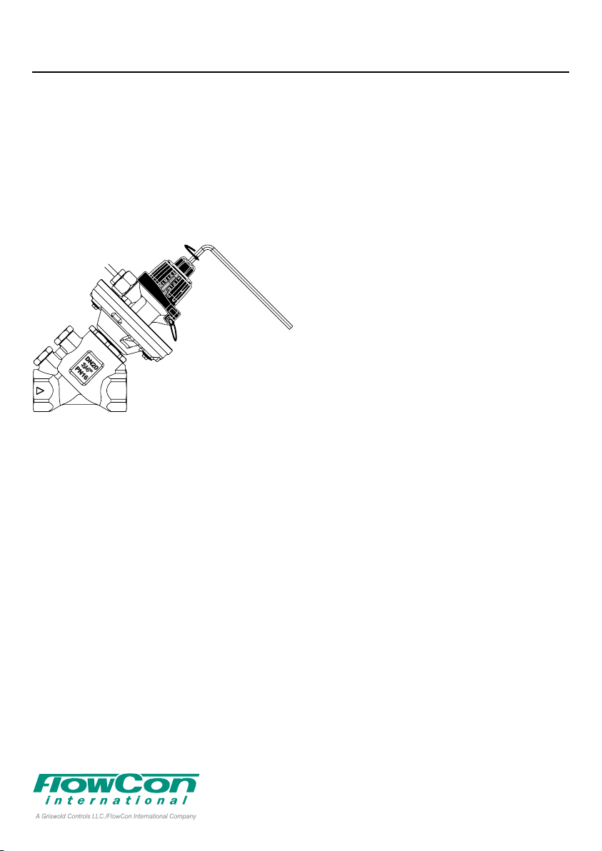
Using the DPCV as a shut-off valve
To use the FlowCon DPCV as a shut-off valve
please use a 4mm hex key on the top as shown
in figure 7. Turn the hex key clockwise (several
rotations) until end point to close the valve, and
counter-clockwise until end point to open the
valve and in order for it to function as a differen
tial pressure control valve again (the setting is
kept). Be sure not to use more than 1Nm torque.
Figure 7
-
General
Water must always be suitably treated, clean
and free from debris. It is recommended that a
strainer be installed prior to the inlet of the capil
lary tube to prevent damage or blockage due to
debris. Further, it is recommended not to exceed
the maximum operational differential pressure.
Warranty obligation
Failure to abide by all recommendations as per
this installation and operation instruction will void
warranty.
When manually operating the valve do not use
more than 1 Nm torque. Using more than 1 Nm
torque will void warranty.
For latest updates please see www.flowcon.com
1H95000 - 04/2016
Denmark Dubai USA Singapore www.owcon.com
FlowCon International assumes no responsibility
- 3 -
for mistakes, if any, in any printed material.
Page 4

DIFFERENT PRESSURE CONTROL VALVEFlowCon DPCV
1H95000 - 04/2016
Denmark Dubai USA Singapore www.owcon.com
FlowCon International assumes no responsibility
- 4 -
for mistakes, if any, in any printed material.
 Loading...