

Page 1

DSfG Gateways C1 and C2
Series 2
Technical Documentation
Function, operation,
commissioning and maintenance
2007 Elster GmbH September 2007
Page 2

Copyright:
2007 Elster GmbH
GAS-WORKS, Z1 and FLOW COMP are German registered
trademarks of FLOW COMP Systemtechnik.
Microsoft, Windows and Windows NT are registered trademarks
of Microsoft Corporation.
Elster GmbH
Schlossstrasse 95a
D - 44357 Dortmund, Germany
Tel.: +49 - 2 31 - 93 71 10 0
Fax: +49 - 2 31 - 93 71 10 99
E-Mail: systems@elster-instromet.com
gas-net C1 and C2
Page ii
Page 3

Contents
Safety and warning notes.................................................................................... v
General Notes on the Structure of this Manual .................................................. vi
1 Introduction ..............................................................................................1-1
1.1 The gas-net system idea..................................................................1-1
1.2 The gas-net DSfG gateway..............................................................1-1
2 How the gas-net DSfG Gateway works....................................................2-1
2.1 Host job list (Data exchange module)...............................................2-2
2.2 DSfG job list (DSfG module) ............................................................2-2
2.3 Foreign Protocols Module (for C2 devices only)...............................2-3
2.4 Simulating a gas quality entity via DSfG
(Gas quality simulation module).......................................................
2.5 Counters module..............................................................................2-4
2.6 Integrated RDT Module (for C2 devices only) .................................. 2-7
3 Device view and design ...........................................................................3-2
4 GW-GNET+..............................................................................................4-1
4.1 Creating and exporting a gas-net parameter data record:
Brief description................................................................................4-1
Importing and editing a parameterisation: Brief description..............4-3
4.2
2-3
4.3 Extras: GW-GNET+ service programs .............................................4-5
5 Installation................................................................................................5-1
5.1 Mounting the gas-net C1 / C2 ..........................................................5-1
5.2 Line Connection ...............................................................................5-1
6 Commissioning.........................................................................................6-1
6.1 Device Parameterisation..................................................................6-1
6.2 Commissioning of the Gateway........................................................6-1
6.3 Commissioning the Integrated RDT .................................................6-2
7 Maintenance.............................................................................................7-1
gas-net C1 and C2
Page iii
Page 4

7.1 Battery Replacement .......................................................................7-1
8 Technical data: gas-net C1 and C2 ......................................................... 8-1
9 Annex.......................................................................................................9-1
9.1 Host protocols..................................................................................9-1
10 Bibliography...........................................................................................10-1
11 Index......................................................................................................11-1
gas-net C1 and C2
Page iv
Page 5

Safety and warning notes
Attention! The following safety and warning notes must be
!
observed:
The gas-net C1 and C2 devices must neither be stored at temperatur es
below -20°C nor above +50°C.
A temperature between 0°C and +40°C must be guaranteed during
operation.
The gas-net C1 and C2 devices must be installed outside ex-zone 2.
The power supply of the gas-net devices is 24 V DC and must be
secured externally by 1 A.
The earthing is connected to PE of the power supply socket for
equipotential bonding.
Observe the regulations of the relevant standards, in particular the
regulations of DIN EN 50014, DIN EN 50020 and DIN EN 50039.
gas-net C1 and C2
Page v
Page 6

General Notes on the Structure of this Manual
The documentation on hand describes the gas-net C1 and C2 DSfG Gateways.
As the description holds mostly for both devices, C1 and C2, we refer generally
to the device 'gas-net DSfG gateway'.
In short, the functional differences between C1 and C2 are the following:
The C2 devic e is availa ble in a mou nting width of 1/3 an d 1/2 (the C 1 has a
mounting width of 1/6) and is therefore able to provide more communication
interfaces. (Several additional foreign digital protocols are supported as
well.)
The C2 supports the functionality Integrated RDT for establishing a data
connection between the gas-net device and a remote center. T his functionality uses the public switched telephone network or GSM wireless network,
a serial direct connection, or TCP.
If a functionality is not available for the gas-net C1, it will be explicitly stated in
the text.
gas-net C1 and C2
Page vi
Page 7

Introduction 1
1 Introduction
1.1 The gas-net system idea
is the generic term for a whole device family. All gas-net devices,
including future device types, stand out due to a uniform
appearance, operation and parameterisation.
The FLOW COMP devices, each by itself, always cover a multitude of measure-
ment and control functionalities.
gas-net devices also provide this functional variet y. To keep the operation and
parameterisation of the devices well structured and user-friendly, the gas-net
series is based on a modular concept. A module corr esponds to a specific functionality, and to each module belongs a group of settings within the parameter
data record. The DSfG gateway gas-net C1, for instance, includes the modules
, DSfG, Data exchange, Counters, and Gas quality simulation.
System
A particular module can be employed in different device types. This yields a
modular system that is advantageous to the user as a particular module can
always be operated and parameterised in the same way, no matter in which
device type it has been installed.
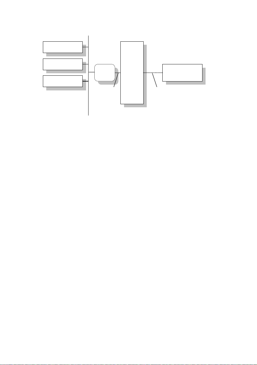
1.2 The gas-net DSfG gateway
The DSfG protocol is a digital data protocol, especiall y developed for the communication between gas metering devices in gas measuring and regulating
stations. However, such gas measuring and regulating stations often also contain a PLC (programmable controller), the tasks of which comprise the openand closed-loop control of the station and telecontrol interfacing to a telec ontrol
centre. Most of the PLCs are not DSfG-capable but use other digital communication protocols
bus.
The gas-net DSfG gateway solves this probl em: This device is connected to the
DSfG bus on the one side and on the other via a digital connection to the PLC
called host in the following.
1
. Consequently, they cannot be simply included in the DSfG
1
Typical protocols are, for instance, 3964R/RK512 (e.g. in case of Siemens S5/S7) or
Modbus-RTU (e.g. in case of Cegelec Modicon).
gas-net C1 and C2 Page 1-1
Page 8
1 Introduction
Correction
Correction
Data logging
DSfG
bus
DSfG
Gateway
digital
connection
Host
Telecontrol centre
Telecontrol line
Typical system structure with an integrated gas-net C1 DSfG gateway
In summary, the gas-net DSfG gateway accomplishes the following tasks:
Cyclic or event-driven data polling at DSfG stations. Conversion of this data
into the host protocol, and its transmission to the host computer.
Cyclic or event-driven data polling at the host computer. Conversion of this
data into the DSfG protocol, and its transmission to DSfG stations.
Simulation of a gas quality entity towards the DSfG bus using gas quality
data provided by the host.
gas-net C1 and C2
Page 1-2
Page 9
Method of operation 2
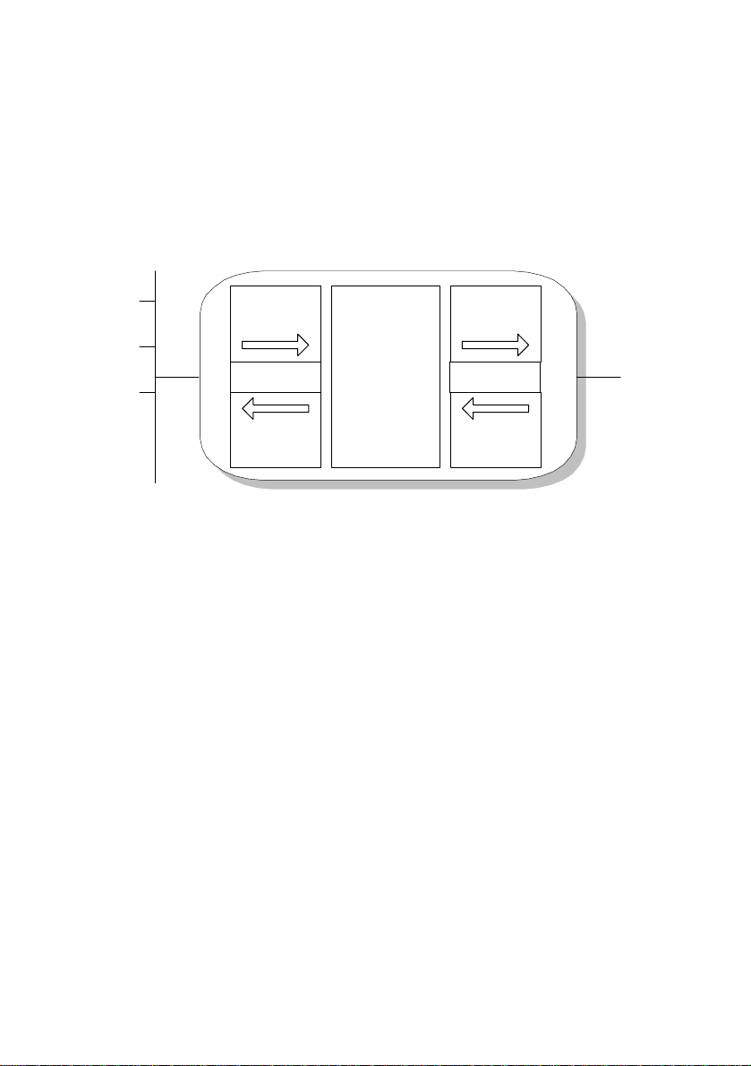
2 How the gas-net DSfG Gateway works
The illustration below shall explain how the gas-net DSfG Gateway works in
principle. The comprehension of the way the gas-net gateway works is essential
for the following description of the device operation and parameterisation.
Import values
Export values
Transfer
DSfG
Bus
DSfG job list
memory,
Calculations
Export values
DSfG
Gateway
Structure of a gas-net C1 DSfG Gateway
Host job list
Import values
Host
The gas-net gateway c yclically executes a jo b list for the DSfG side and o ne for
the host side, one independent of the other. The results of import jobs are always stored as data points in a transfer memory, whereas export jobs always
take their data points from the transfer memory that has been filled before. The
job lists themselves are generated by a PC during commissioning and parameterised in the gateway.
To a limited extent, the gas-net DSfG Gateway can also calculate with the data
points of the transfer memory. This function will be described in the foll owing
chapters, too.
gas-net C1 and C2 Page 2-1
Page 10

2 Method of operation
2.1 Host job list (Data exchange module)
The job list of the host describes all data flows to be processed between host
and gas-net DSfG Gateway. The system distinguishes between the flow direction to the host (data export) and the flow direction from the host (data import).
The data transport in the direction to the host is processed cyclicall y. If a new
value arrives from the DSfG side, the associated export value will be updated. In
addition to the specification of the destination in the host, the description of the
export value also defines the way of positioning the data point in the host (e.g.
size, scaling, limits, bit position).
A particular import value describes for the reverse data flow direction from which
position in the host a data point shall be collected and in which way it shall be
converted. It can be parameterised whether the transmission to the DSfG side
shall be performed cyclically or event-driven.
Any number of import values from the host can be combined to a job group. All
data points of a job group are always put into the transfer memory altogether
and simultaneously, but only after all of them have been collected again onc e
more. Moreover, a job group may be linked with a trigger. A trigger is a defined
position within the host. It initiates a new processing of a job when its content
has changed.
2.2 DSfG job list (DSfG module)
The DSfG job list describes all data flows to be processed between the DSfG
stations and gas-net DSfG Gateway. The system distinguishes between the flow
direction to DSfG stations (export values) and the flow direction from DSfG stations (import values).
A particular import value for a DSfG station describes the DSfG data e lement
that shall be collected and put into the transfer memory. F or this, any numerical
data element provided by the addressed station can be addressed, without
exception.
Several import values of one and the same DSfG station are combined to a job
group, a so-called query telegram. All data elements of a query telegram are
collected via DSfG queries and thus always put into the transfer memory altogether and simultaneously. DSfG import groups also comply with some special features of the DSfG regulations relating to the telegram traffic. For instance, it is possible to process query telegrams either cyclically or upon the
gas-net C1 and C2
Page 2-2
Page 11

Method of operation 2
arrival of an attention telegram2. You can also collect the most recent entry of a
3
standard query
. Finally, the processing of each individual query telegram can
be blocked. This function is useful if the associated DSfG station is temporarily
not in operation.
2.3 Foreign Protocols Module (for C2 devices only)
The Foreign Protocols module is incorporated in the C2 software only a nd facilitates the connection of several manufacturer-specific protocols (e.g. the Uniform protocol).
This functionality is intended for special applications; please contact Elst er for
further information.
2.4 Simulating a gas quality entity via DSfG
(Gas quality simulation module)
The simulation of the gas quality data is a ver y special function of the gas-net
DSfG Gateway. The DSfG regulations stipulate a specific process that
announces the existence of a new gas quality analysis across DSfG and distributes this analysis to all stations interested in it. However, if there is no gas
quality analyser incorporated in the gas measuring and regulating station, and
the gas quality data is injected via the telecontrol system, the gateway may
inject this remotely provided gas quality data in the DSfG bus as if it were a gas
2
According to the DSfG specifications the DSfG entities may generate attention telegrams
in case of special events. These attention telegrams are routed to all devices on the bus
as multi-address message.
3
A DSfG standard query serves to collect several coherent dates of a DSfG station at
once by querying with a single data element. For instance, via the “bia” data element you
address the standard query 1 of a volume corrector entity. The response to this query
supplies all current totalizers and important measurements. Other standard queries are
updated upon certain events. The standard query 2 (“bib”) for a volume corrector, for
example, is always updated at the end of an interval or at the beginning and end of
alarms. Each time such a data record is logged the ordinal number increases by one.
When polling via an ordinal number, such standard queries always supply exactly the data
record that belongs to the indicated ordinal number. The information on the highest ordinal
number ("level indicator") is also available via a DSfG data element. This way, you are in
the position to collect the most recent entry of a standard query via DSfG.
gas-net C1 and C2
Page 2-3
Page 12

2 Method of operation
quality analyser itself. Thus, a gas quality analyser is being simulated for the
DSfG entities interested in gas quality data (e.g. for volume correctors). It provides a new analysis each time an analysis is supplied via the host.
2.5 Counters module
The M1’s counting function may file counters for different ph ysical values, comprising Counters and Totalizing counters. The created count va lues are available across the system and thus can, for instance, be logged, output and in
particular queried via DSfG.
2.5.1 Counters and Conversion Factors
The so-called Counters create a totalizer based on an input value consisting of
either a count value or a flow rate. This input value may either be supplied by a
transmitter directly connected to the device (e.g. a gas meter with encoder totalizer, Q.Sonic or FLOWSIC ultrasonic gas meter or a meter with a pulse i nterface) or come in via a digital protocol from an external source (e.g. via DSfG or
MODBUS).
If the incoming count value (possibly determined based on the flo w rate) is a
volume, it can be multiplied by a conversion factor to create the counter. T his
way a counter for the base volume, energy or mass can be created based on an
input of the volume at operating conditions. A base volume input can be used for
creating an energy or mass totalizer.
To define or calculate the factor, a so-called convers ion factor is assign ed to the
counter. The definition of such a conversion factor comprises the following
specifications:
- Hs and Rho as constants
- k-ratio calculation method k=const or SGERG-88 or no correction (if the
totalizer input value already is the base volume)
- Pressure and temperature inputs (consideration of online values for the
calculation of the compression factor Z)
Up to 5 conversion factors can be parameterized, each of which may be assigned to different counters at the same time.
gas-net C1 and C2
Page 2-4
Page 13

Method of operation 2
The following table shows useful combinations for counters being weighte d with
a conversion factor:
Input value Target
value
Factor for counter k-ratio calculation
method
V or Q V *Z k=const or SGERG
E *Z *Hs k=const or SGERG
m *Z *Rho k=const or SGERG
V or Q E *Hs no correction
m *Rho no correction
A counter is considered being disturbed in one of the following cases:
- The optional related message input Disturbance information has been set.
- The input value for the creation of the c ounter is disturbed (protocol timeout,
cable break, etc.)
- A coefficient is disturbed (e.g. the pressure input value of a parameterized
conversion factor)
If the totalizer is transferred digitally, it is possible to either transfer the original
totalizer or to create an own counter. Totalizers/counters being cr eated by the
device itself can be set via the data interface by means of the GW-GNET+ software during an online connection. The setting of totalizers i s subject to the user
lock (numeric code).
The Counters module is able to file up to 100 counters.
2.5.2 Counters - Intercalating Totalizers
If an input totalizer comes in via a digital protocol only at regular intervals, the
option Intercalate totalizer is available to achieve that the counter increases
continuously and not suddenly.
Based on the input values the Intercalate totalizer functionality creates a count
value, which is updated continuously. This updatin g is based on the change of
the incoming count value during the previous time interval and can thus n ot start
unless valid count values permitting a calculation of the average change have
arrived two times in a row.
This calculated average change per time interval is continuousl y added to the
internally created totalizer. As soon as the next totaliz er arrives, the ch ange rate
is calculated anew, thus achieving that the difference in case of deviations between the created totalizer and the original totalizer is compensated over the
gas-net C1 and C2
Page 2-5
Page 14

2 Method of operation
course of time. The original totalizer is thus not just automatically transfer red to
the created totalizer. This is important because a possible running backwards of
the intercalated totalizer must be prevented.
An intercalated totalizer will fluctuate around the original tot alizer when the flow
rates are changing. In principle, this totalizer can only re present an approximate
value, which is the more precise the lower the flo w rate fluctuations are and the
more often a new intercalation value comes in.
The procedure is only started anew if an error occurs, such as a mains failur e,
an error of the totalizer input value or an exceeding of the parameterizable
communication timeout. As soon as the error is no longer pending, the newly
supplied totalizer will be transferred to the intercalated totalizer and the creatio n
of the intercalated totalizer will be restarted.
There is a special procedure for recognizing the setting of a totalizer: A maximum flow rate Qmax is parameterized that must not be exceeded. An implausible totalizer increment violating the defined maximum flow rate is interpreted as
“setting”. In such a case, too, the new totalizer will be immediately transferred to
the intercalated totalizer and the creation of the intercalated totalizer will be
started anew.
Furthermore, the intercalation of the intercalated counters is stopped belo w a
flow rate of 1/10 of the maximum flow rate. In such a case o nly the totalizers
being supplied via the protocol will be transferred to the i ntercalated totalizer.
This prevents that the intercalated totalizer reading is higher than the original
totalizer when the station is shut.
2.5.3 Totalizing Counters
A totalizing counter totalizes up to 10 counters and creates a total count value.
Each of the involved counters may be included in the totalizing counter with a
positive or negative sign. If all involved counters have a flow rate input value, a
total flow rate is additionally created.
A totalizing counter is considered being disturbed if at least one of the involve d
counters is disturbed.
If a counter with a negative sign influences a totalizing counter, the overall result
should always be positive. Nevertheless, it may happen from time to time that, in
terms of figures, a negative total increment occurs – for instance, in case of
pulse inputs with different input types (HF, LF). A totalizing counter nev er counts
backwards. An internal buffer retains negative quantities instead. The retained
gas-net C1 and C2
Page 2-6
Page 15

Method of operation 2
negative quantities will be subtracted as soon as the total increment is positive
again.
The negative quantities can be deleted with a menu command. In addition,
accumulated negative quantities of a totalizing counter are al ways deleted when
the counter changes from the disturbed to the undisturbed status.
A total flow rate is always positive; if a negative value is determin ed in terms of
figures, the total flow rate is set to 0.
Total flow rate and total count value are available as values across the system;
therefore, they can in particular be logged and output.
Totalizing counters can be set via the data interface using the GW-GNET+ software during an online connection. Possibly retained negative quantities are
deleted when a totalizing counter is set. The setting of a counter is subject to the
user lock (numeric code).
The Counters module can file up to 20 totalizing counters.
2.6 Integrated RDT Module (for C2 devices only)
The Integrated RDT (Remote Data Transmission) module implements the data
connection between the gas-net device and a remote center. The center
accesses the data traffic as a logical equal-access station via the integrated
RDT during an established data connection. The data transmission is implemented according to DSfG specifications by means of a Class B DSfG interface.
If the device is equipped with a DSfG interface, further devices may be connected via this interface. If such a local DSfG bus exists, the connection to the
center not only refers to the communication with the entities inside the device
but with the entire local DSfG bus traffic. With respect to data communications,
the RDT integrated in the device thus completely replaces an independent DSfG
RDT as other devices connected via DSfG may also use it.
The parameterization of the gas-net device assigns an own bus address
(EADR) to the internal Center via RDT entity
4
.
The data connection may use one of the following transmission media:
4
According to DSfG terminology an Entity is an enclosed functionality within a device. One
single entity is not necessarily identical with an enclosed device, as a device may contain
different entities with their own DSfG bus addresses.
gas-net C1 and C2
Page 2-7
Page 16
2 Method of operation
1) Public switched telephone network or GSM wireless network (hardware
requirements: modem, COM2 interface)
2) Serial direct connection (hardware requirements: null-modem cable, COM2
interface)
3) TCP (hardware requirements: computer network, TCP/IP interface)
Independent of the data transmission type, the data connection establis hed by
the integrated RDT offers multiple diagnostic and information gathering possibilities.
For example, it is possible to poll archive data from a remote location. However,
the RDT may also be parameterized in such a way that a special event (e.g. a
correction alarm) will trigger a call at the center. This works as follows: According to the DSfG Specification, the entities gener ate Attention telegrams that are
forwarded to all other stations in form of a multi-address message in case of
special events. It is possible to separately define for e ach station that the center
5
will be informed spontaneously in case of particular generated telegram types
.
5
Each DSfG telegram contains a character for the telegram type (TTY). The telegram type
identifiers of the currently valid attention telegram types are the following:
Telegram type TTY
Bus alarm B
Freeze request F
Hint H
End of billing period I
Alarm L
New measurement M
Parameter change P
Warning W
Make-specific meaning Y
Timesynch telegram Z
gas-net C1 and C2
Page 2-8
Page 17

Method of operation 2
Re 1) Data connection via modem and telephone line or GSM wireless network
The data connection usually uses either the public or the company telephone
network. If a system is not connected to a line-bound telephone net work, a connection can be implemented via the GSM wireless network.
An external modem is connected to the COM2 interface of the gas-net device
for connection to the respective telephone network.
In order to check the access authorization of the center, the integrated RDT
manages the bus address, bus identifier and password of the center (Center
identifier). A login procedure is carried out during a call connection. If errors
occur during this procedure, each side is authorized to inter rupt the connection
by ‘hanging up’ for in this case a faulty connection or an unauthorized access
can be assumed.
The remote center, however, is only linked via the integrated RDT during an
established telephone connection. If the transmission of attention telegrams has
been parameterized, the center will be spon taneously called and informed. For
this, the integrated RDT has to know the center’s telephone number.
Furthermore, it is possible to synchronize the internal device time via the integrated RDT if there is a server reachable by telephone and provi ding the time
via telephone in accordance with a defined protocol. Should you b e interested,
please consult Elster-Instromet systems to clarify the usability of this functionality in your case.
Re 2) Serial direct connection (null-modem cable)
In case of a serial direct connection the RDT assumes a continuous connection,
i.e. a leased-line operation. The interface har d ware is conne cted by a thre e- core
null-modem cable; control lines are therefore not supported. T he RDT is always
online, so there is no connection set-up, no login procedure, and no connection
tear-down. Telegrams to DSfG Class B may arrive at the RDT at any time and
are processed there accordingly, i.e. they are answered by internal b us stations
or routed to the local DSfG bus. Attention telegrams from local entities are
spontaneously sent by the RDT via the leased lin e to the center directly after
their creation.
This operating mode is thus intended for applications for which a continuously
established serial direct connection is guaranteed.
gas-net C1 and C2
Page 2-9
Page 18

2 Method of operation
Re 3) TCP (computer network)
The TCP connection type is intended for applications which use a T CP/IP network for the transmission of DSfG data. The easiest way is to imagine this operating mode without the modems and telephone network and with an IP network
instead. Only the hardware is exchanged an d telephone numbers are replaced
by IP addresses. The connection remains being a dial-up network (between any
IP address of the network and the IP address of the RDT). Like in case of the
telephone dial-up network the connection set-up may be initiated by the cente r
or local RDT.
In addition to the IP addresses of RDT and center, the values for the subnet
mask and gateway usually used in the IP world an d the port to be used for the
transmission are special parameters of the TCP connection.
In case of this operating mode the preferred service for time synchronization
would be NTP, which is a common network service.
A center that also supports DSfG queries via TCP/IP network is required for this
operating mode; e.g. GW-Remote+.
The use of the TCP/IP network is advantageous for applica tions provided wit h a
nearby IP network. In this case modem and telephone net work can be saved.
gas-net C1 and C2
Page 2-10
Page 19

3 Device view and design
3 Device view and design
The housing of the gas-net C1 is designed as slide-in unit for a 19”-frame with a
width of 1/6, the gas-net C2 device has a mounting width of 1/3 or 1/2.
The front panel of the device contains the following operating and display
elements:
8 LEDs for status indication.
One pushbutton for triggering a general polling.
One user switch protecting particular parameters from being changed when
it is in the closed position. You can only export an entire parameterisation
data record into the device if the user switch is open (cf. Chapter
The DSS data interface for the connection of a P C or laptop for servicing purposes.
The following illustration shows, as an example, the front view of a gas-net C1
(narrow design with a mounting width of 1/6):
Status LEDs:
Master glows if the C1 is the bus master on
the DSfG bus.
Polling Fault indicates that the DSfG station
list has changed.
Transmission, Reception signal data
communications with the DSfG bus.
Host Fault blinks if the communication with
the host is disturbed.
Data to Host / Data from Host signal data
communications with the host.
Status: The status LED glows green when
the device operates normally.
4.1).
Data interface
DSS
Page 3-1
gas-net C1 and C2
Pushbutton for
triggering
general pollings
User switch.
Close the user switch
by turning it clockwise as far as it will
go.
Page 20

Device view and design 3
In addition to the 24 VDC mains connection up to two of the following interfaces
are located on the back of the device:
DSfG interface
COM2 interface: serial interface accordi ng to RS232. Intended for connec t-
ing the modem for the integrated RDT (supported by C2 devices only).
Alternatively suitable for connecting proprietary protocols (Modbus RTU,
Modbus ASCII, RK512 or 3964R)
TCP/IP for integration in a standar d network installation (for data e xchange
via Modbus TCP or time synchronization via NTP)
Additionally, the C1 provides a slot for a gas-net process board (typically, a
serial process board MSER2 is installed here). A gas-net C2 device with a
mounting width of 1/3 accommodates up to four process boards.
The illustration below shows a typical rear view of a C2 device with a mounting
width of 1/3.
MSER2 serial process boards
Free board locations for gas-net process
boards with suitable lettering panel
gas-net C1 and C2
DSfG or COM2
COM2 or TCP/IP
interface
(optional)
24VDC input voltage
Page 3-2
Page 21

GW-GNET+ 4
4 GW-GNET+
gas-net devices are always parameterised via the GAS-WORKS software
system with a PC or laptop. All gas-net devices are parameterised with the
same GAS-WORKS module, called GW-GNET+.
The next two sections generally explain how to create or edit a complete gas-net
parameterisation using GW-GNET+ and how to export it to the device. It is easy
to learn how to work with the parameterisation program. As soon as you have
mastered the techniques you only need to k now the mea ning and effect o f each
adjustable parameter, no matter which gas-net device type is actually concerned. This is why we have enclosed a complete parameter list with additional
information in the annex to this documentation.
For a detailed description of the parameterisation program, pleas e refer to the
GW-GNET+ online help. It also describes other editing methods the parameteri-
7
sation program offers.
We recommend activating the context-sensitive online help of GW-GNET+ in
case of concrete questions.
4.1 Creating and exporting a gas-net parameter data record: Brief description
Should you want to create a completely new gas-net parameterisation, ple ase
proceed as follows:
6
1. Start GW-BASE from the Windows environment by double-clicking the
lantern icon.
6
Please refer to the GAS-WORKS CD-ROM, which is part of the delivery scope of each
gas-net device, for further information on the GAS-WORKS program system with all the
possibilities it provides. All GAS-WORKS components can be installed from this CD, which
also contains the operating instructions for all GAS-WORKS modules, in particular GWGNET+.
7
It is possible to change the device parameterisation or individual parameters when the
data connection between computer and device is established. These methods are
advantageous to different situations: For instance, particular parts of the parameterisation
can be exchanged in the GW-GNET+ Edit parameterisation mode, even if the user
switch is closed. In the Change parameter mode parameters characterised as online
changeable can be edited without a device restart being necessary.
gas-net C1 and C2
Page 4-1
Page 22

4 GW-GNET+
2. Invoke the GW-GNET+ module by clicking the New – Create gas-net
parameterisation tool in the toolbar. Alternatively, you may select the
Tools – New – Create gas-net parameterisation menu item from the main
menu.
3. Select the device type you want to parameterise in the appearing dialo g box
and in the next step the version number of the device s oftware. Choose an
existing standard parameterisation, on which the new parameter data
record shall be based, in the following dialog box.
After you have confirmed your selection by clicking OK, the GW-GNET+
interface is activated.
4. Within the Modules and Linkages window, each module included in the
device software is listed by name and the corresponding icon. By doubleclicking this line you activate a dialog listing all parameter s that belong to
the module concerned.
Adjust the settings according to your requirements.
Tip: There is a corresponding topic for every adjustable parameter within
the context-sensitive online help (mark the parameter and press Ctrl + F1).
5. Go through all modules in this way until all adjustments meet your
demands.
6. Select File – Save as, and enter the name under which the parameter data
record shall be saved in GAS-WORKS. Close GW-GNET+, for instance via
the File – Exit menu item.
7. The parameter data record is now in the worksheet of GW-BASE. Before
exporting it to the device, you have to drag it into a suita ble hierarch y of the
8
GAS-WORKS data management.
8
To drag a data record from the worksheet into a hierarchy, proceed as described below:
1. Mark the target hierarchy (which you must possibly create first).
2. Drag the data record from the worksheet into the right half of the configuration window
using the mouse.
Alternatively, you can also drag the data record directly to a folder in the hierarchy (on the
left in the configuration window).
Please refer to the GW-BASE online help for further information.
Page 4-2 gas-net C1 and C2
Page 23

GW-GNET+ 4
8. Connect the D SS data interface at the dev ice to a COM computer interface
using a parameterisation cable.
9. Turn the user switch at the device to “open”.
10. Mark the parameter data record and select the Data – Export menu item
from the main or context menu of GAS-WORKS.
11. The communication program starts.
The window appearing on your monitor shows the information Data trans-
mission to gas-net device.
After the transmission has been finished, the device will be restarted. The
message Data transmissio n to gas-net device disappears from the communication window. The type plate of the connected gas-net device is
shown instead, indicating the most important device data.
You can close the communication program now.
4.2 Importing and editing a parameterisation:
Brief description
You can read out the current parameterisation of a gas-net device via the data
interface and edit it afterwards.
The following description explains how to read the parameterisation into your
computer:
1. Connect the COM interface of the computer to the DSS interface at the gas-
net device using a parameterisation cable.
2. Start GAS-WORKS on your computer if it has not been started already.
Activate the communication program by clicking the Impo rt – Data inter-
face tool in the GW-BASE toolbar.
After having successfully started the communication program you are linked with
the connected device data technology-wise. The window appearing on your
monitor shows some important basic device information.
3. Select the Content tab now.
4. Mark the Parameterisation data record, and click the lantern icon.
A Save as dialog box appears asking for the name under which the data
record shall be saved in GAS-WORKS.
After you have entered the name and confirmed your entry b y clicking OK,
the reading in of the data will start.
gas-net C1 and C2
Page 4-3
Page 24

4 GW-GNET+
5. After the reading in has been finished, you can close the communication
program via the main menu item File – Exit.
The parameter data record is filed in the GAS-WORKS worksheet under the
specified name. Before you can start GW-GNET+, you have to file this data
record away in the hierarchy. It is principally impossible to process data records
9
when they are still in the worksheet.
And this is how to edit an existing parameter data record:
1. Mark the parameter data record in the configuration window of GW-BASE.
2. Select Data – Edit from the main or context menu.
GW-GNET+ starts.
3. Edit the parameterisation according to your demands.
4. Save the changes you made:
By clicking Save you save the data record under its old name.
If you select the Save as menu item, you can save the data record under a
new name. In this case, the newly created data record is transferre d to the
GW-BASE worksheet first and must then be incorporated in a suitable
10
hierarchy.
5. Close GW-GNET+, and export the changed parameterisation as descri bed
in Chapter 4.1, steps 8 to 11.
9
For brief instructions see footnote 8, page 6-2.
10
For brief instructions see footnote 8, page 6-2.
Page 4-4 gas-net C1 and C2
Page 25

GW-GNET+ 4
4.3 Extras: GW-GNET+ service programs
The GW-GNET+ program includes some additional service programs fulfilling
different tasks relating to gas-net devices. The range of available service programs depends on the gas-net device type.
For instance, the following tools are available for gas-net C1 and C2 devices:
Edit
parameterization
Change
parameters
DSfG bus access Starts GW-REMOTE+ via the data interface, if
for changing the parameterization during an established data connection to the device.
Purely operational parts of the parameterization can
be changed this way, even though the user switch is
closed.
Note: Please refer to the GW-GNET+ online help for
further instructions.
for changing individual parameters during an established data connection to the device.
Note: Please refer to the GW-GNET+ online help for
further instructions.
installed. Facilitates the data access to all devices
connected via DSfG; for instance, for reading out
archive data and viewing current data.
These programs may only be activated via the DSS data interface with the data
connection being established. Proceed as usual:
1. Start GW-BASE on your laptop.
2. Connect the DSS interface of the gas-net d evice to a COM interface of the
laptop using a parameterisation cable.
3. Start the communication program by clicking the Import – Data interface
tool in the GW-BASE toolbar. After the data connection to the device has
been established, the type plate of the connected device appears on your
monitor.
4. Select the Tools tab. The appearing tab lists all available service programs.
5. Start the desired program by double-clicking it.
The functional range of the service programs is manageable an d practical. T hey
are therefore quite easy to operate. Comprehensive online help, which can be
activated via the Help – Content menu item or by pressing the F1 key, is available for each program.
gas-net C1 and C2
Page 4-5
Page 26

Page 27

Installation 5
5 Installation
5.1 Mounting the gas-net C1 / C2
The gas-net devices are desig ned for mounting in a 19”-cabinet; the gas-net C1
has a mounting width of 1/6 whereas the width of the gas-net C2 is 1/3.
A mounting depth of 170 mm must be taken into consideration to leave the terminals on the back accessible. We recommend mounting the d evice in a swing
frame.
The gas-net devices must be installed in an explosion-free plant area
(where electrical appliances are located) according to protection class
IP 20.
5.2 Line Connection
The device must always be load-free during the connection of the generator,
supply, signal and data lines.
Any modification of the wiring is only permitted if the supply has been
disconnected before!
The connection of the signal lines to the gas-net dev ice is i mpleme nted via pl uggable screw terminals each of which is located in a cable terminal box. The
power supply is connected via fixed screw terminals. Data lines have to be connected to the according SUB-DB9 connector housings.
Please consider the relevant installation guidel ines when arranging the wiring.
The lines must be tensile stress-free and must be provide d with a bend protection, if the gas-net device is mounted in a hi nged bay. T he cable length must be
dimensioned in such a way that there is no tensile stress on the cable during the
swinging of the swing bay.
5.2.1 Power supply and earthing
Operate the gas-net C1 or C2 device with a nominal voltage of 24 V DC.
The connection of 24 V is implemented via the terminals
the device and must be protected externally against short circuits with 1 A. The
internal device protection is guaranteed by a self-resetting overcurrent protector.
Connect the protective earth to PE of the power supply socket for equipotential
bonding.
gas-net C1 and C2 Page 5-1
+ and – on the back of
Page 28

5 Installation
5.2.2 MSER2 Serial Process Board
The MSER2 serial process board provides two interfaces supporting V24
(RS232) as well as RS422 and RS485. The table below shows the assignment
of the individual pins:
An MSER2 board must always be installed in the device if an u ltrasonic gas flow
meter (type Q.Sonic or FLOWSIC) is connected via RS485. Another application
of an MSER2 board is the connection of a host computer via RK512/3964R or
MODBUS protocol or the connection of a GPS receiver for the time synchro nization.
Notes:
When RS422 and RS485 are used, a terminating resistor of 120 ohms may
be required in the receiver between RXB and RXA, dependi ng on the cable
length.
In case of RS485, you have to externally connect RXB to T XB and RXA to
TXA.
Please pay attention to the specification of the individual pr otocols. For ins tance,
there are protocols that render a connection via RS485 impossible (e.g. in case
of RK512).
Signal Assignment
TXD RS232: Transmitted data
RXD RS232: Received data
RXB RS422/RS485: Received data (B)
RXA RS422/RS485: Received data (A)
TXB RS422/RS485: Transmitted data (B)
TXA RS422/RS485: Transmitted data (A)
SGD Signal ground
SCH Shield
5.2.3 Serial interface DSS
The serial interface DSS consists of a SUB-DB 9 female conn ector mounted on
the front and serves to connect the gas-net C1 or C2 to other devices, such as a
laptop or PC. A connecting line to the computer can be supplied as accessory
equipment. A standard COM connection (one-to-one connection) is not
missible.
Page 5-2 gas-net C1 and C2
per-
Page 29

Installation 5
5.2.4 DSfG interface (optional)
The DSfG protocol is an internal protocol for gas meters for data transmission
between devices of the gas-net series.
The DSfG interface is a SUB-DB 9 male connector located o n the back of the
device. Secure the connector with screws.
5.2.5 TCP/IP Interface (optional)
The TCP/IP interface is an RJ45 socket at the back of the device. It facilitates
the communication via Ethernet with 10/100 MBit/s and thereby integrates the
device in a standard network installation. In addition to time synchronization
based on the NTP protocol, remote inquiries and the Modbus-TCP protocol for
exchanging data with external devices are also possible via the TCP/IP
interface.
The IP address, subnet mask and gateway address must be parameterized for
an adequate integration in the existing network infrastructure. Please pay
attention to the fact that the IP address must be unambiguous in the subnet.
Please ask the network administrator for the subnet mask and gateway address.
The use of an STP CAT5 network cable (not transposed) is mandatory.
The pin assignment of the RJ45 socket corresponds to the general Ethernet
standard.
The TCP/IP interface adjusts itself automatically to the network transmission
rate.
5.2.6 COM2 interface (optional)
The COM2 interface is a serial interface to RS232 and may be us ed as protocol
interface for the connection of a host computer.
The corresponding pin assignment is as follows:
Pin
Signal Signal name Assignment of the 9-pin
no.
1 DCD Data carrier detect -2 RXD Received data
3 TXD Transmitted data
4 DTR Data terminal ready --
gas-net C1 and C2
rectangular connector
used for RK512/3964R and
MODBUS
used for RK512/3964R and
MODBUS
Page 5-3
Page 30

5 Installation
5 GND Signal ground
used for RK512/3964R and
MODBUS
6 DSR Data set ready -7 RTS Request to send -8 CTS Clear to send -9 RI Ring indicator --
Screen -- Chassis
has the same potential as the
protective ground
In case of a C2 device, the COM2 interface may be used for the connection of
the modem or null-modem cable for the functionality of the integrated RDT.
The connection of a wireless modem
requires special attention and thus some
preparations that must be accomplished before you may actually commission
the device:
Provider Selection / Preparation for Antenna Selection
The first step is the selection of a suitable provider for the usage of the
wireless network, with consideration of area coverage and service rates. The
provider’s data service hast to use the RLP protoc ol for data backup. The
converter (gateway) of the provider has to offer an error protocol conversion
according to MNP4 and V42, respectively.
In order to be able to select the correct antenna, check the data signal quality on site; for instance, check the field strength by means of a normal mobile
phone.
Also check the installation possibilities for the antenna. Es pecially consider
the characteristics of the building. An external installation is al ways preferable. Attention is to be paid to the station’s environment. In case of stations
located within built-up areas an antenna that can be protected ag ainst vandalism might be useful.
It is also important to measure the distance between antenna and modem t o
be able to order the antenna cable in the required length.
Component Composition
As soon as you have finalized the contract with the provider you have to
apply for the data service. Furthermore, make sure that the data service will
be released by the scheduled commissioning date and that the chip card will
be available, too.
Select the antenna depending on the determined data signal quality and
preferably after consultation with Elster-Instromet Systems.
Page 5-4 gas-net C1 and C2
Page 31

Installation 5
The following specifications are guidelines:
Field strength Suitable antenna
High omnidirectional dipole antenna with mounting
Medium to low
Low directional antenna for pole mounting
base
flat omnidirectional antenna, also for external
mounting and for mounting on metal surfaces
The length of the antenna cable to be ordered depends on the distance
between modem and antenna.
Commissioning of Wireless Modem
Have the PIN number at hand, if required.
After having installed the antenna, connect it to the modem using t he antenna cable. The antenna must be aligned to the maxim um receiving level,
except for the case that the antenna is an omnidirectional one.
Note: The further commissioning of the integrated RDT with wireless modem
is described in Chapter
6.3. It is especially important for the further proceeding to enter the correct PIN number of the SIM card in the parameterization
data record of the gas-net device. Please also observe the following notes
on the correct voltage connection of a Siemens M20 or TC35 wireless modem:
gas-net C1 and C2
Page 5-5
Page 32

5 Installation
Connection of the Siemens M20 / TC35 Wireless Modem to 24 V
Unfortunately, no generally valid colorcoding details can be given for the
connection of the M20 or TC35 wireless
modem to 24 V DC. Due to the variety
of different cables supplied, it is not
possible to guarantee a uniform color
coding.
Therefore, please proceed as follows:
Position the Western plug of the connecting cable in such a way that the
locking catch is at the front and pointing
upwards. Look at the clamped cable:
There are 6 wires. The assignment of
the wires from left to right can be seen
11
from the illustration on the right.
In this way it is also possible to assign
the color coding correctly at the open
end of the cable and to connect the
voltage supply correctly.
Note: Wires 3 and 6 must both
be connected to +24 V! These are monitoring
and supply signals.
11
The illustration shows a Siemens M20 wireless modem, but holds by analogy for the
Siemens modem type TC35.
Page 5-6 gas-net C1 and C2
Page 33

Commissioning 6
6 Commissioning
6.1 Device Parameterisation
A complete parameterisation as well as a modification of all parameters are
executed via PC / laptop computer. The parameter data record is cr eated by
means of the parameterisation software GW-GNET+.
Note: Please refer to Chapter
means of the GW-GNET+ program. For a comprehensive description of the
parameterisation program, please refer to the GW-GNET+ online help.
6.2 Commissioning of the Gateway
The following instructions explain the commissioning of a gate way step by step.
It may be helpful to have a look at the device view in Chapter
to check where the individual LEDs, interfaces and connections are located.
Check the installation and wiring of th e gas-net C1 or C2 gateway in de-
energised conditions.
Pull off the connector marked DSfG on the back of the gas-net device. Also
pull off the connector that establishes the connection to the host (at COM2).
If necessary, consult the specifications of your DSfG bus installation for the
intended position of the end-of-line resistors. A bus termination or open-c ircuit generation is not necessary if exclusively gas-net devices are connected to the DSfG bus. If you connect also other stations to the bus, other
devices must ensure the bus termination and supply. In this case, plea se
ask the respective manufacturer for information. Also, make sure to comply
with the regulations of the DVGW Code of Practice G 485
Connect the gas-net DSfG gateway to the supply volta ge. Make cert ain tha t
the device contains the desired parameterisation.
Verify the following indications on the front of the DSfG gate way: The stat us
LED glows green. If the gateway is the DSfG bus master, i.e. the EADR “-“
has been assigned to it, then the Master LED glows. As the host has not
been connected yet, the Host Fault LED flashes red.
4 for a brief instruction on the parameterisation by
3 from time to time
12
.
12
For source of supply see Appendix (Bibliography).
gas-net C1 and C2
Page 6-1
Page 34

6 Commissioning
Plug in the connector that establishes the connection to the host at COM2
on the back of the gas-net device now. If the connection is physically and
logically okay, the data connection must be established instantaneously if
the host has been switched on and configured acc ordingl y. You may rec ognise this by the lighting up of the Data to Host/Data from Host LEDs on
the front of the DSfG gateway. Moreover, the Host Fault LED must have
gone out.
If the data exchange is physically okay but the data cannot be inter preted,
you have to check the associated parameter settings. For instance, a different transmission rate may have been set erroneously for gateway and host.
Plug in the connector marked DSfG on the b ack of the DSfG gateway, thus
connecting the local DSfG bus. Perform a general polling at the devic e being the DSfG bus master, i.e. the device with the EADR “_”. If the DSfG
gateway is the bus master, you can initiate a general polling by pressing the
pushbutton marked General polling on the front of the gas-net DSfG gateway. The LEDs Transmission /Reception are flashing alternately. Even
after quite some operating time has elapsed, the Polling Fault LED must
not glow (unless you have changed the number of bus stations), for this
would indicate that the bus structure is erroneous or some bus stations are
unreliable.
Check, possibly by means of a make-dependent host-programming device,
whether all data points agreed in the DSfG gateway are being exchanged.
When you are convinced that the DSfG bus and host protocol run reliably at
the DSfG gateway, start with a systematic test. Each data point being
transferred should be checked from its point of creation (sensor simulation)
to its final destination (e.g. the telecontrol centre). The test is only finished,
after all data points have been thoroughly tested in this way.
The commissioning is now completed. Remove the parameterisation cable, and
make sure again that the Polling Fault LED still does not glow. The gas-net
DSfG gateway should now run reliably and free of maintenance.
6.3 Commissioning the Integrated RDT
Parameterize the settings for the integrated RDT (together with all other
parameters of the gas-net device) using the GAS-W ORKS module GW-GNET+.
Page 6-2 gas-net C1 and C2
Page 35

Commissioning 6
Please pay attention to the consistency of the paramet er data record; it is especially important to choose the correct modem.
Different procedures are necessary for commissioning the integrated RDT,
depending on the operating mode (dial-up line, GSM modem or TCP/IP network).
Dial-up line
Dial-up Line:
1) Remove the DSfG connector on the back of the gas-net device if a local
2) Connect the modem and COM2 interface at the gas-net device using the
3) Switch the supply voltage of the gas-net device off and on again.
4) If there is a local DSfG bus, plug in the connector marked DSfG on th e
GSM
GSM wireless
modem
TCP/IP network
DSfG bus exists.
supplied V24 cable. Pull the telephone plug out of the TAE socket outlet.
Switch to the basic display of the Integrated RDT module.
The current status of the RDT is visible here. The device will try to initialize
the modem directly after start-up.
If the initialization fails, you will regularly receive No modem status messages between the individual initialization attempts. Check the modem settings of your parameterization in this case.
Once the initialization has been successful, the status indication will
change from Modem initialization to Basic status.
back of the gas-net device.
Perform a general polling at the device representing the bus master, i.e.
which contains the entity with the EADR “_”.
Invoke the DSfG menu (System module) at the gas-net device, if this
hasn’t happened yet. You may view the station list here and compare it
with the planned bus configuration to check.
13
13
If an entity of the gas-net device is the bus master, initiate the general polling via the
operator panel at the device:
Switch to the main display of the System module.
Invoke the menu and select the subordinate menu item DSfG.
Press the Menu key again and confirm the subordinate menu item General polling.
gas-net C1 and C2
Page 6-3
Page 36

6 Commissioning
5) Call your center and verbally announce the connection test. Switch the
device off and immediately on again; this way you avoid the call delay
times that may have been activated already and thus a waiting period.
Then plug the cable into the TAE socket outlet.
If a routing job has already been pending, the RDT establishes the connection to the center. If this is not the case, you have to trigger an event
that induces the RDT to call first; for instance, a correction module alarm.
The main menu of the Integrated RDT module indicates the RDT’s status
change. Once a data connection has been established and data has been
exchanged, the RX and TX LEDs keep blinking irregularly on the back of
the device.
6) After the connection to the center has been terminated successfully, check
the telephone connection in the other direction. This means that the call
has to originate in the center. The connection is implemented as described
above. The employee at the center should formally release the telephone
connection from his point of view.
Page 6-4 gas-net C1 and C2
Page 37

Commissioning 6
GSM Wireless Modem:
Important note: Before starting with the commissioning of the integrated RDT,
make sure the accurate PIN number of the SIM card has been set in the
parameterization of the gas-net device (Integrated RDT module). T he reason is
that the entry of a wrong PIN is only possible twice; if you enter the wrong number a third time, the SIM card will be deactivated.
1) Remove the DSfG connector on the back of the gas-net device if a local
GSM
DSfG bus exists.
2) Disconnect the wireless modem from the supply and pull the V24 cable off
the gas-net device.
Check whether the V24 cable is plugged in the modem. Test the antenna
installation (has the antenna been connected?).
Insert the chip card in the modem if you haven’t done it yet
.
3) Switch off the gas-net device and plug in the V24 cable at the COM2
interface. Switch the GSM modem and gas-net device on again.
4) Change to the basic display of the Integrated RDT module. The current
status of the RDT is visible here. The device will try to initialize the modem
directly after start-up.
If the initialization fails, you will regularly receive No modem status messages between the individual initialization attempts. Check the modem settings of your parameterization in this case.
Once the initialization has been successful, the status indication will
change from Modem initialization to Basic status.
If the status indication shows the text RDT not in operation, the SIM card
could not be recognized (for instance, because the card is defective or the
PIN is not parameterized correctly). In such a case, the integrated RDT
remains deactivated until the next start-up of the device will take place.
5) Check the modem’s data signal quality via the Integrated RDT – GSM
menu (cf. description in Volume 1 under Integrated RDT Module, Display
and Operation).
6) If there is a local DSfG bus, plug in the connector marked DSfG on th e
back of the gas-net device. Perform a general polling at the device representing the bus master, i.e. which contains the entity with the EADR “_”.
14
Invoke the DSfG menu (System module) at the gas-net device. You can
view the station list here and compare it with the planned bus configuration
14
If an entity of the gas-net device is the master, please refer to Footnote 13, Page 8-
Fehler! Textmarke nicht definiert., for information on how to perform a general polling.
gas-net C1 and C2
Page 6-5
Page 38

6 Commissioning
to check.
7) Call your center now and announce the connection test.
8) If a routing job has already been pending, the RDT establishes the connection to the center. If this is not the case, you have to trigger an event that
induces the RDT to call first; for instance, a correction module alarm.
The main menu of the Integrated RDT module indicates the RDT’s status
change. Once a data connection has been established and data has been
exchanged, the RX and TX LEDs keep blinking irregularly on the back of
the device.
9) After the connection to the center has been terminated successfully, check
the telephone connection in the other direction. This means that the call
has to originate in the center. The connection is implemented as described
above. The employee at the center should formally release the telephone
connection from his point of view.
TCP/IP Network:
1) Remove the DSfG connector on the back of the gas-net device if a local
DSfG bus exists.
2) Remove the network connector from the respective socket at the gas-net
device.
Go to the main display of the Integrated RDT module.
It shows the current status of the RDT. The device will try to initialize the
integrated network module directly after start-up.
If the initialization fails, you will regularly receive Module error status messages between the individual initialization attempts. Check whether your
gas-net device is actually equipped with a network module.
Once the initialization has been successful, the status indication will
change from Initialization to Basic status.
3) If there is a local DSfG bus, plug in the connector marked DSfG on th e
back of the gas-net device. Perfo rm a general polling at the device representing the bus master, i.e. which contains the entity with the EADR “_“.
15
Invoke the DSfG menu (System module) at the gas-net device if this has
not happened yet. It is possible to view the station list here and compare it
with the planned bus configuration to check.
4) Now plug the network connector in the corresponding socket at the gas-net
device. Call your center and ask for the connection test. The center staff
15
See Footnote 13.
Page 6-6 gas-net C1 and C2
Page 39

Commissioning 6
now have to establish a connection to the IP address of your RDT with
their data polling tools (which must support DSfG connections via network)
and check the data polling. Once the connection has been successful, the
main menu of the Integrated RDT module indicates the status change of
the RDT.
5) After the connection has been successfully established by the center, the
network connection has possibly to be checked in the other direction afterwards. This step has only to be taken if DSfG-related events shall
spontaneously be signalized to another center via the network. This center
must be able to receive DSfG calls via network. In this case the RDT wants
to establish the connection. To initiate such a connection request, you first
have to trigger an event that induces the RDT to call; e.g. an alarm. The
connection will then be established as described above.
Afterwards, the center staff should release the connection.
gas-net C1 and C2
Page 6-7
Page 40

Page 41

Maintenance 7
7 Maintenance
gas-net devices do not require much maintenance.
7.1 Battery Replacement
The device battery mainly runs down when the device is switched off. The battery consumption can be neglected as long as the device is switched on.
The battery should therefore be replaced after 5 years when in the meantime
the device has been switched off for a longer period of time. Otherwise it is
sufficient to replace the battery after 10 years at the latest.
If the battery must be replaced, this should only be executed by a service engineer or trained expert for safety reasons.
Important: The old battery must be disposed properly; i.e. it must either be
returned to the distributor (Elster-Instromet Systems) or handed in at special
battery take-back facilities.
To exchange the battery, you need to open the housing of the gas-net device.
Proceed as described below:
A battery of the following type is required: lithium 3V CR ½ AA.
Save the device parameterization by reading it out with GAS-WORKS, to be
on the safe side. Read out the archives, too.
Disconnect the supply voltage.
Loosen the 4 fixing screws on the back of the device.
Slightly withdraw the mounting rail.
Attention: The boards are sensitive! Avoid any contact with other components!
The battery compartment is (seen from behind) on the board located back
at the top on the far right side. Detach the cover strap of the battery co mpartment with a screwdriver. Remove the old battery. Now you have 15
minutes for the battery exchange. During these 15 minutes a data backup is
guaranteed by a capacitor. Insert the new battery.
gas-net C1 and C2 Page 7-1
Page 42

7 Maintenance
Note: When inserting the battery, pay attention to the correct polarity: The
positive pole (+) must point downwards! A wrong polarit y will not be notic ed
at first, but during the next power failure that lasts more than 15 minutes the
device data will be lost.
Re-assemble the device and connect the supply voltage.
Page 7-2 gas-net C1 and C2
Page 43

Technical Data 8
8 Technical data: gas-net C1 and C2
Device type
Electronic DSfG gateway.
Housing
Plug-in unit in 19”-design, 3 height units, 1/6 mounting width (C1 devices) or 1/3
mounting width (C2 devices) for swing frame mounting. M ounting depth without
connectors: approx. 170 mm, with connectors: approx. 220 mm. The process
interfacing is implemented on the back of the device.
Power supply
24 V DC +/- 20 %; power input: approx. 4 W. As an option: 230 V AC vi a external power supply.
Indicating instruments
LEDs for indicating the status on the front and back of the device.
Interfaces
DSS data interface for the connection to the COM interface of a PC or laptop for
parameterization.
Optional DSfG interface for data transmission between gas-net devices.
Optional COM2 interface (serial interface to RS232C) for connecting the host;
maximum transmission rate: 38400 baud.
In case of a C2 device, the COM2 interface may alternati vely be used for connecting a modem with a maximum transmission rate to V.34 bis (33600 baud)
and data compression to V.42 or NMP5 (Integrated RDT functionality). An integrated RDT is also possible via a serial dir ect connection (null-modem cable at
COM2).
Optional TCP/IP interface in form of an RJ45 socket; facilitates data communication via Ethernet with 10/100 MBit/s and thereby integrates the device in a
standard network installation. In addition to time synchronization based on the
NTP protocol, remote inquiries and the Modbus-TCP protocol for exchanging
data with external devices are also possible via the TCP/IP interface.
gas-net C1 and C2 Page 8-1
Page 44

8 Technical Data
Parameterization
Commissioning and parameterization via the PC software GAS-WORKS. Parameter data records can be stored, documented and ma naged in the PC under
GAS-WORKS.
Page 8-2 gas-net C1 and C2
Page 45

Annex 9
9 Annex
9.1 Host protocols
9.1.1 RK512 / 3964R
The gas-net D SfG gateway supports the protocol consisting of 3964R (dat a link
layer) and RK512 (data presentation).
Look up the settings of the protocol parameters in exactly this form in the manuals of the programmable controller, and adjust them in the communications
processor procedure.
The implementation of the RK512 protocol in the gas-net Gateway is restricted
to the data transmission between data blocks. The smallest information unit is a
so-called data word. Such a data word has a length of 16 bits and may co ntain,
for instance, several messages, a status overview in the form of a bit string, or a
binary measurement.
The structure of the management of these data words is rather simple; there are
up to 256 larger units, data blocks, each of which may c ontain up to 256 data
words. Data blocks and words are numbered consecutively from 0 to 255, with
the numbers serving as addresses.
A single data word is clearly defined by exactly three details:
the address of the data block (0..255)
the address of the data word (0..255)
the content of the data word
The addresses to be assigned to the host data in the gateway parameterisatio n
therefore consist of a data block/data word (DB/DW) pair. The data block 0 is
usually used for intrasystem host variables. This is why yo u should use the data
block 0 neither for exporting values towards the host nor for importing host
values.
In some special cases the host only masters the subordinate 3964R protocol
layer.
This means that the following restriction applies: As no DB/DW information is
transmitted on the 3964R protocol level, all data to be exported or imported
must be arranged in a row. The number of data is thus limited to 64 data words
per transmission.
gas-net C1 and C2 Page 9-1
Page 46

9 Annex
This is why in the GW-GNET+ interface the positions for import a nd export values are not indicated in the DB/DW form but as serial register numbers.
We therefore recommend to switch to the 3964R protocol type in the program's
surface first, if necessary, and then to position the export data points or import
values during the creation of the parameterisation.
The necessary programming of the host can be minimised by selecting the
Master operating mode for the gateway side of the RK512 protocol. In this case
it is not necessary to compile a job list for the host as the entire data block
assignment is carried out via the gateway parameterisation. However, at least
the agreed data blocks and the basic protocol functionality must be defined in
the host of course.
The communication between the host and the gas-net DSfG gateway is subject
to several basic requirements. The following list provides a summary:
Communication protocol: RK512/3964R – point-to-point
Interface: V24 with PC/AT pin assignment at the gateway
Transmission rate: adjustable to 2400, 9600, 19200 or 38400 baud
Transmission parameters: 8 data bits, even parity, 1 stop bit
3964R telegrams: max. 128 bytes (64 data words) per telegram
RK512 response telegrams: Max. 64 data words per telegram; no 3964R tele-
gram chains possible. In the RK512 slave operating mode (i.e. gateway = slave), the gateway
generates the response telegrams listed in the
table below:
Page 9-2 gas-net C1 and C2
Page 47

Annex 9
Error
number
00H ------------ OK telegram after SEND
0CH Memory access - A data block has been addressed, which does
10H Instruction 2 The second instruction letter is wrong. Here, only 'D'
11H Access not
16H Instruction 1 The first instruction letter is wrong. Only 'A' for S END
34H Telegram length - The telegram that arrived was incomplete (not
S5/S7 Error
designation
permitted
Cause of error
not correspond with the data block of an RK512
job.
- The first addressed data word is not within the
data area of the addressed data block.
- The addressed data is longer than the
addressed data block.
for DB is permitted.
A telegram with data has been sent, but no access
rights for its DB/DW area exist.
and 'E' for FETCH are admissible.
enough data).
- The length stated in the SEND telegram and the
length of the telegram itself do not correspond.
gas-net C1 and C2
Page 9-3
Page 48

9 Annex
9.1.2 MODBUS RTU / MODBUS AS CII
The Modbus protocol is supported, for instance, by the PLC series of AEG
Modicon.
The data presentation according to the Modbus protocol is one-dimensional.
The smallest data unit in the memory consists of 16 bits. The protocol contains a
number of registers, which are numbered consecutivel y from 0 up and each of
which may contain exactly such a 16-bit word. In each indi vidual case the number of registers depends on the size of the memory available on the host side.
The positions of the import and export values of the host are indicated as serial
register numbers in the parameterisation of the gas-net Gateway, too. These
register details always refer to the MODBUS telegram presentation, which may
lead to different register numbers in the PLC, depending on the host type.
Communication protocol:
Interface:
Transmission rate:
Transmission parameters:
Modbus telegrams:
Based on Modbus RTU/Modbus ASCII
according to the Modicon Modbus Protocol
Specification (Jan. 1991, MODICON Inc.),
point-to-point.
V24 with PC/AT pin assignment at the gas-net
device.
adjustable to 2400, 9600, 19200 or 38400 baud
Modbus RTU 8 data bits, Modbus ASCII 7 data
bits.
Even parity, 1 stop bit pre-allocated.
Maximum of 250 bytes (125 register words) per
telegram.
Only the Modbus telegram types 03 and 16 are
supported.
Modbus response
telegrams:
In the gateway = slave operating mode, the
gateway generates response telegrams when
an error occurs. These telegrams are listed in
the table below:
Page 9-4 gas-net C1 and C2
Page 49

Annex 9
Error
number
Modbus error
designation
Cause of error
01 illegal function The telegram type received is not
permissible, i.e. it is neither of the 03 nor of
the 16 telegram type.
Only Modbus telegram types with the
functional numbers 03 (= read holding
registers) or 16 (= preset multiple registers)
are needed in the gateway; this why only
these are supported.
02 illegal data address The indicated data address is not
permissible.
04 failure in
associated device
Other
gas-net C1 and C2
Page 9-5
Page 50

Page 51

Bibliography 10
10 Bibliography
Technische Spezifikation für DSfG-Realisierungen, Gas-Information Nr. 7,
1. Überarbeitung 05/00
(Technical Specification for DSfG Implementations, Gas Information No. 7, 1st
revision 05/00), only available in German
Order no.: ISSN 0938-6114
Publisher: DVGW, Postfach 140362, D-53058 Bonn, Germany, May 2000
Sold by: Wirtschafts- und Verlagsgesellschaft Gas und Wasser mbH,
Postfach 140151, D-53056 Bonn, Germany
Technische Regeln, Arbeitsblatt G485, Digitale Schnittstelle für Gasmessgeräte
(DSfG)
(Technical regulations, Code of Practice G485, Digital Interface for Gas Meters
DSfG), only available in German
Order no.: ISSN 0176-3490
Publisher: DVGW, Postfach 140362, D-53058 Bonn, Germany, September 1997
Sold by: Wirtschafts- und Verlagsgesellschaft Gas und Wasser mbH,
Postfach 140151, D-53056 Bonn, Germany
DIN EN 50014, DIN EN 50020, and DIN EN 50029
gas-net C1 and C2 Page 10-1
Page 52

Page 53

Index 11
11 Index
B
Battery replacement 7-1
Bibliography 10-1
C
C1
Front panel 3-2
C1, C2
Device view and design 3-2
Installation 5-1
Technical data 8-1
C2
rear view 3-3
COM2 Interface 5-3
Commissioning 6-1
Integrated RDT 6-2
Connection
DSfG 5-3
Conversion factor 2-4
Counter
Intercalate totalizer 2-5
Counters 2-4
Counters module 2-4
D
Data blocks 9-1
Data exchange module 2-2
Data interface DSS 5-2
Data word 9-1
DSfG
Job list 2-2
DSfG bus access 4-5
DSfG Gateway
Principle 2-1
DSfG Gateway
Tasks 1-2
DSfG module 2-2
DSS 5-2
G
Gas quality entity
Simulating 2-3
gas-net
Introduction 1-1
GQ simulation module 2-3
GSM wireless modem
Antenna 5-5
GW-GNET+ 4-1
Service programs 4-5
H
Host
Job list 2-2
Host protocol
RK 512/6964R 9-1
I
Import
Parameterisation 4-3
Installation 5-1
Integrated RDT 2-7
Commissioning 6-2
Integrated RDT module
Function 2-7
Interface for host connection 5-3
L
Line connection 5-1
gas-net C1 and C2 Page 11-1
Page 54

11 Index
M
Modbus protocol 9-4
MSER2 5-2
P
Parameterisation 4-1
Creating 4-1
Import 4-3
Pin assignment
COM2 5-3
R
RDT
Null modem 2-9
RK512/3964R protocol 9-1
S
Safety and warning notes v
Serial process board
MSER2 5-2
T
TCP/IP interface 5-3
Totalizing counter 2-6
W
Wireless modem M20 / TC35
Connection to 24 V 5-6
gas-net C1 and C2
Seite 11-2
 Loading...