

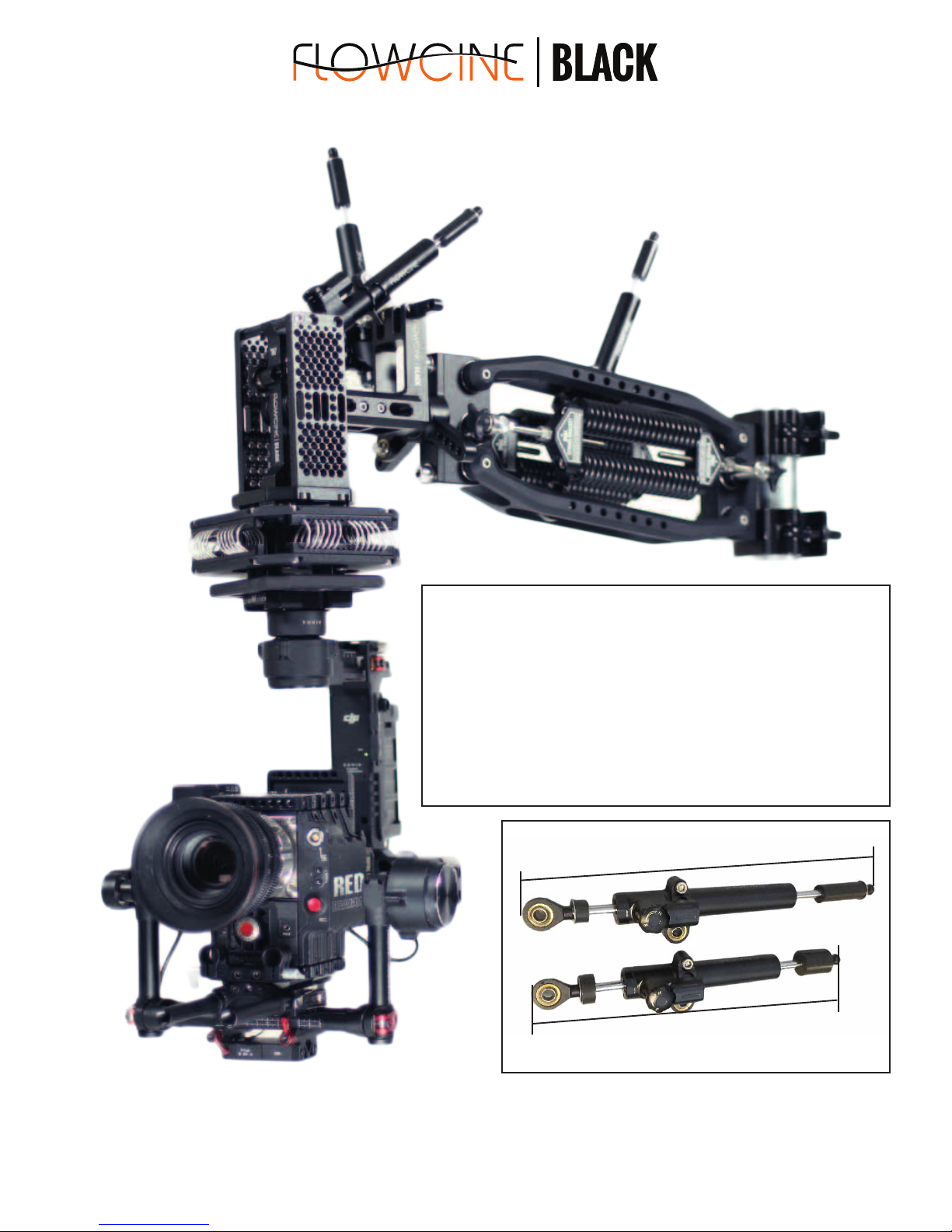
Flowcine Black Arm Instructions Manual
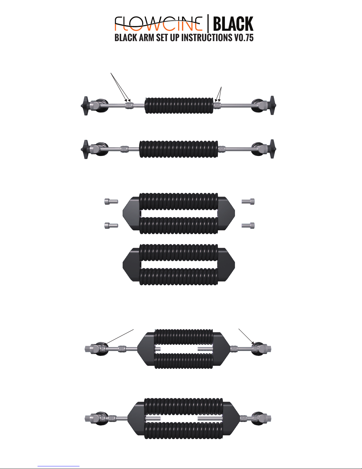
BLACK ARM SET UP INSTRUCTIONS V0.75
Please read through the full documentation, before using the arm for the first time! The documentation includes configurations and
help for troubleshooting most problems encountered on set.
QUICK GUIDE SETUP AND CONFIGURATIONS FOR: BLACK ARM STANDARD & BLACK ARM COMPLETE
NOTE! The current manual contains instruction/placement
for the first generation dampeners. There is another manual
out soon for second generation (shorter) dampeners soon.
You can tell difference by looking at the soft end stops on the
dampeners. ALL first generation dampeners will be replaced
by Flowcine, as soon as possible, due to production errors
emailed earlier. If you have a urgent problem with your
dampener, please email info@flowcine.com. Thank you!
1st gen dampener (thin rubber end stop opposite end of ball joint)
2nd gen dampener (thick rubber end stop)
337mm
297mm
BLACK ARM SET UP INSTRUCTIONS V0.75
SINGLE SPRING 7.0 (Pre-installed for BLACK ARM STANDARD users): 2 x 7 mm (1x7 per side) for payload up to 14kg / 31 lbs payload. Max extension 25mm.
NOTE! Always insert tension screw equally on each side when mounting a new spring.
Dual nuts (Optional). Keeps the spring from unintentionally wind/un-wind itself.
And keep track on which side to tension from.
Single nut & washer (Optional). Helps keep the dual spring bracket to align straight and not rotate, while there is no load on the springs. Always loosen these
before ANY tensioning is done. You can use a nut&washer on each side, on one side or not use them at all (not necessary when the arm is in action).
Dual nuts (Optional ). Helps you keep track of the maximum safety tension limit of 25mm.
The distance is set, from a relaxed spring (before any tensioning). Use a caliper
or equal to check distance between spring and nut before usage or change of springs.
BLACK ARM SPRING GUIDE:
Single 7.0
SINGLE SPRING 7.5 (Pre-installed for BLACK ARM COMPLETE users): 2 x 7.5 mm (1x7.5 per side) for payload up to 19 kg / 42 lbs payload. Max extension 25mm.
Single 7.5
DUAL SPRING 7.0: 4 x 7.0 mm (2x7.0 per side) for payload up to 28 kg / 62 lbs payload. Max extension 25mm per side.
To change to DUAL SPRING configuration. User the dual spring brackets, and insert the supplied M8x25 screws on each side. Then attach the dual spring
brackets on the tension screws. Please always ensure to grease the tension screws before usage, to minimize friction when tensioning.
Dual 7.0
DUAL SPRING 7.5: 4 x 7.5 mm (2x7.5 per side) for payload up to 38 kg / 84 lbs payload. Max extension 25mm per side.
Dual 7.5
BLACK ARM SET UP INSTRUCTIONS V0.75
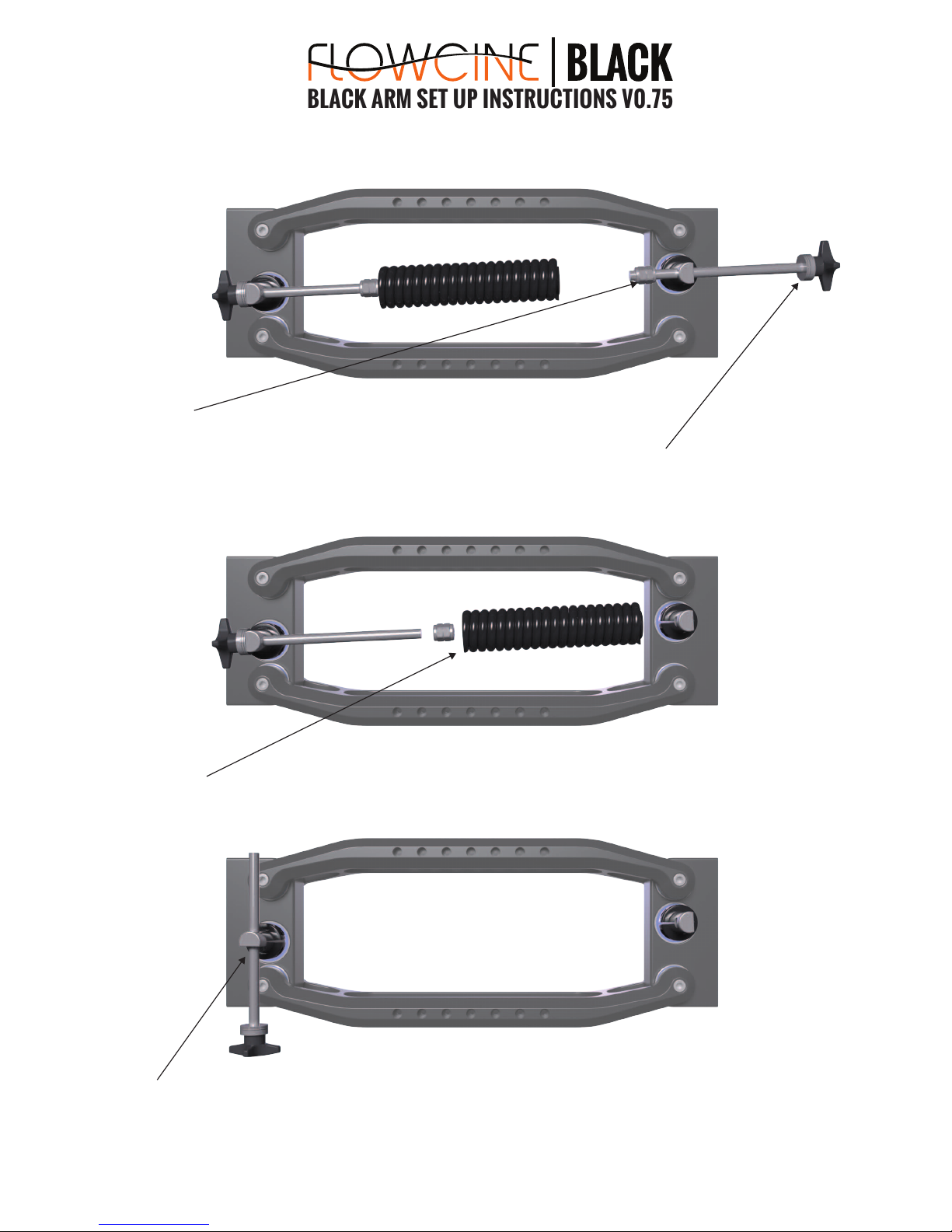
1. Lessen the tension on the tension screw on the backside of the BLACK ARM (near the clamps). And follow along
moving the dual nuts that sets the tension safety limit until the tension screw is completely removed.
2. Be sure, not to drop the thrust bearings at the end of the tension screw. These are necessary to enable smooth friction when turning the knob.
3. Once one tension screw is removed, you can easily unwind the spring, and remove the dual nuts on the other side.
4. Rotate the shaft/tension screw and drag it out from below.
BLACK ARM SPRING/TENSION SCREW REPLACEMENT ILLUSTRATION:
BLACK ARM SET UP INSTRUCTIONS V0.75
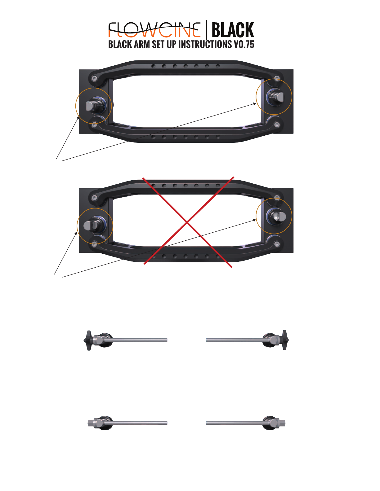
5. Note correct shaft direction! The shafts should always have the flat surface facing from centre of the arm.
6. Incorrect direction of shafts. If being used the thrust bearings will be bent and lead to problem.
7. Tooless tension knobs. Usually used when using single 7.0 or 7.5 spring configuration when friction isnt to large. You can use hexagon tension screw
on one side, and knob on the other if you like.
8. Heaxgon nut tension screw. Four of these are shipped and packed in the BLACK ARM case, if you prefer to use the supplied ratchet wrench nr 13 for tensioning.
BLACK ARM SET UP INSTRUCTIONS V0.75
3. If you have a toad-in-the hole or cinemilled mount, you insert the screws from the backside of the base plate. Other mounts can either be mounted directly
from the front of the base plate, using the 3/8”-16 threads. IF you have a gimbal/gyrohead with non-compatible pattern, please let us know and we try to help
you out as soon as possible.
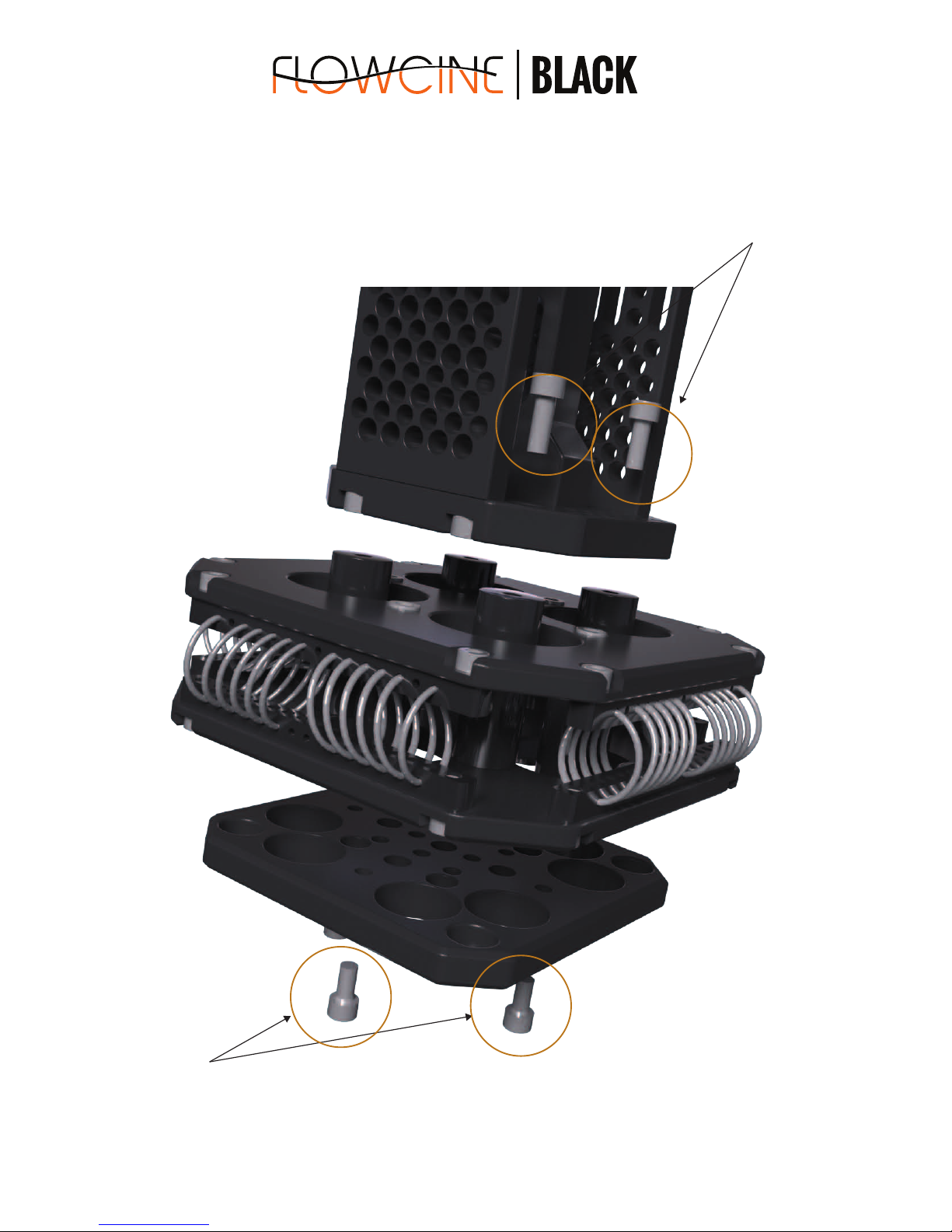
2. Once your vibration mount is removed from the BLACK ARM, remove bottom 4x M6x16 screws using a allen key #5.
Be sure to use mild/medium Loctite thread gluewhen fastening them again (we recommend Loctite 243).
VIBRATION MOUNT / GIMBAL INSTALLATION:
 Loading...