

Page 1
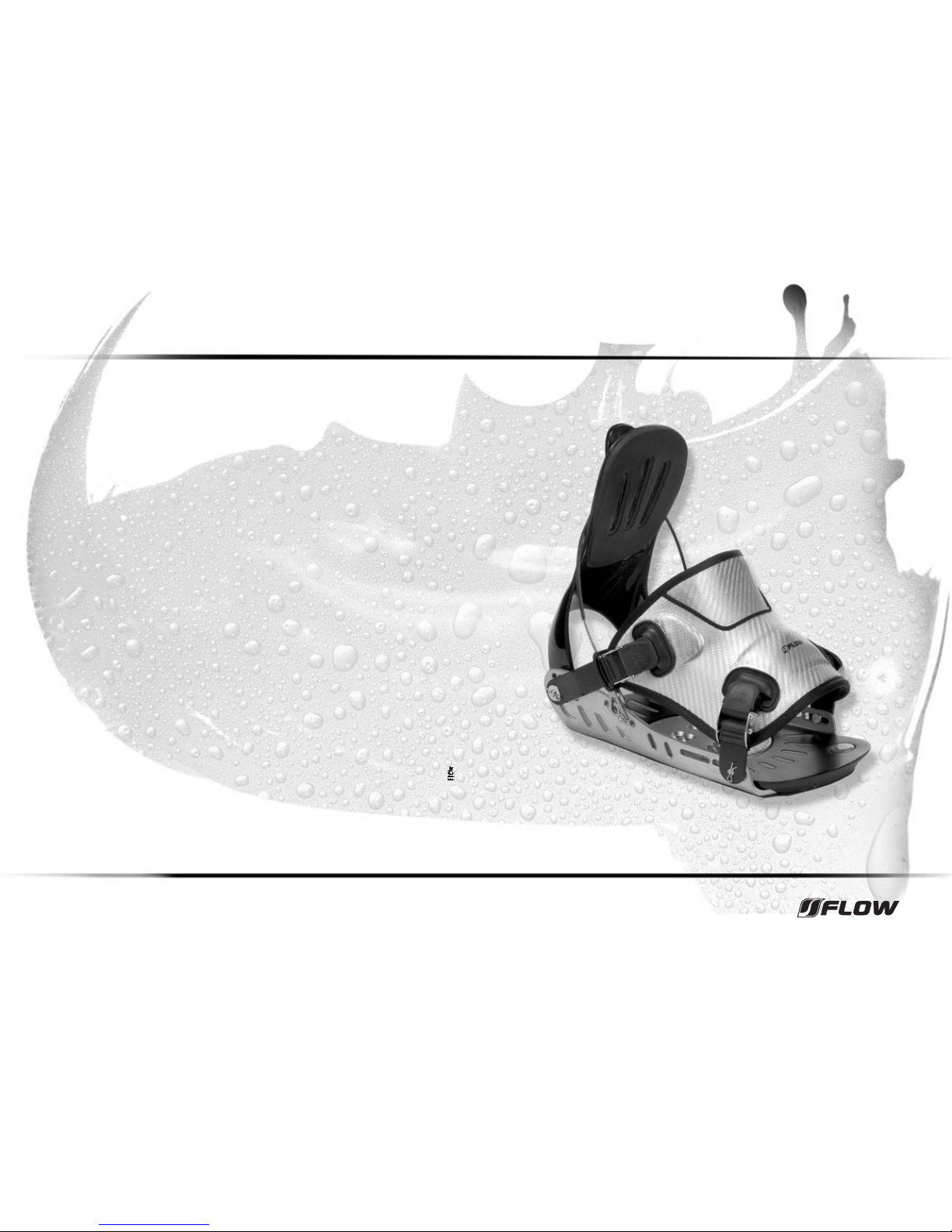
team binding
manual
Flow and the Power Triangle
®
are registered trademarks of Goodwell International Ltd.
www.flow.com
ARGENTINA
Tsunamy SA
Av. del Libertador 13.275
Martinez B1640AOD, Buenos Aires
Tel: +54/ 11 4792 1133
Fax: +54/ 11 4733 3796
e-mail: [email protected]
AUSTRALIA
I.B.P. Pty Ltd.
Balgowlah Business Park, Unit 2
28-34 Roseberry Street, Balgowlah
Sydney, NSW, Postal Address, P.O. Box 36
Balgowlah 2093
Tel: +61/ 2 9949 1400
Fax: +61/ 2 9948 6352
e-mail: [email protected]
AUSTRIA
On Sports
Gewerbepark Gaerberbach 11
A - 6020 Innsbruck
Tel: +43/ 512 583 573-11
Fax: +43/ 512 583 573-17
e-mail: [email protected]
BENELUX
Adventure Sports Benelux
Beneden Oostdijk 24
NL-3261 KX Oud-Beijerland
Tel: +31/ 186 643232
Fax: +31/ 186 614212
e-mail: [email protected]
CANADA
UTC Ltd.
180 Industrial Parkway North
Aurora, Ontario L4G 3H5
Tel: +1/ 905 841 4001
Fax: +1/ 905 841 4006
e-mail: [email protected]
CHILE
Windsurfing Chile
Las Carmelitas 30
Las Condes alt, 7000 Santiago
Tel: +56/ 2 2111959
Fax: +56/ 2 2115735
e-mail: [email protected]
CROATIA
AB original d.o.o.
Kranjcviceva 16, 1000 Zagreb
Tel: +385 (1) 3630 921
Fax: +385 (1) 3630 923
e-mail: [email protected]
CZECH REPUBLIC
Snowboard Zezula
Jasminova 12, 621 00 Brno
Tel: +420/ 5-492 74516
Fax: +420/ 5-41 22 9191
e-mail: [email protected]
DENMARK
Neil Pryde Scandinavia Ltd.
Golfvej 10, DK - 7400 Herning
Tel: +45/ 97 22 4943
Fax: +45/ 97 122 412
e-mail: [email protected]
ESTONIA
Extreme Sport AS
Paldiski mnt 102 C, 13522 Tallinn
Tel: +372 (665) 9130
Fax: +372 (665) 9131
e-mail: [email protected]
FINLAND
Jari Laakso Oy
Lukkosepankatu 6, 20320 Turku
Tel: +358/ 2-278 4280
Fax: +358/ 2-278 4284
e-mail: [email protected]
FRANCE
Neil Pryde Europe
373, bd. De la République, BP 39
F - 62232 Annezin,
Tel: +33/ 3 21 64 65 30
Fax: +33/ 3 21 56 09 85
e-mail: [email protected]
GERMANY
Open Ocean Sportartikel GmbH
Schleifweg 7, D - 74257 Untereisesheim
Tel: +49/ 71324025
Fax: +49/ 71324026
e-mail: [email protected]
GREECE
K. Kokkolios & Co. O.E.
17, Chr. Smirnis, Kallithea 176 72, Athens
Tel: +30 (210) 956-4168
Fax: +30 (210) 931-0023
e-mail: [email protected]
HONG KONG
Wind n’ Surf
Shop-A1, L/G., Wilson House
19-27 Wyndham Street, Central
Tel: +852/ 2366 9293
Fax: +852/ 2366 3671
e-mail: [email protected]
HUNGARY
Hi – Surf Ltd.
Hegyalja ut 176 (313), H-1112 Budapest
Tel: +36/ 1 214 9054
Fax: +36/ 1 214 9054
e-mail: [email protected]
IRAN
Modern Sport Co., Ltd.
No. 94 North Jordon, Tehran 19156
Tel: +9821/ 2050380, 2048733
Fax: +9821/ 2051167
e-mail: [email protected]
ISRAEL
M. Gravity
32 Yigal Alon St., Herzelia 46324
Tel: +972/ 53 986469
Fax: +972/ 9 9575796
e-mail: [email protected]
ITALY
Wurz S.R.L.
Zona Artigianale 21
I - 39052 Caldaro (BZ)
Tel: +39/ 0471 962 233
Fax: +39/ 0471 964 048
e-mail: [email protected]
JAPAN
Shriro Trading Co. Ltd.
Sports Goods Department
The Itoyama Tower 8F
3-7-18, Mita Minato-Ku
Tokyo 108 - 0073
Tel: +81/ 3 5440 7601
Fax: +81/ 3-5440-5699
e-mail: [email protected]
KOREA
OMK Corporation Ltd.
1/F, Keundong B/D, 192-22,
Nonhyun-Dong, Kangnam-Ku, Seoul
Tel: +82/ 2549 2737, 23446-8194
Fax: +82/ 2514 1105
e-mail: [email protected]
LATVIA
Baltwest Sia
Klugu Iela – 3C, Riga, LV1084
Tel: +371 / 7031076
Fax: +371 / 7031077
e-mail: [email protected]
LEBANON
Les Deux Domaines - Yellow Cab Surfing
Centre highway, Ajaltoun-Kesrouan
Tel: +961/ 3 776577
Fax: +961/ 1 331210
e-mail: [email protected]
LITHUANIA
X-Pro Vandens Sporto Centras
Pramones pr. 15, 3031 Kaunas
Tel: +370686 33993
Fax: +37037 452029
e-mail: [email protected]
NEW ZEALAND
Wild Winds Sail – Surf – Snow
Jibe Connection
Chaffers Marina Oriental Bay Wellington
P.O. Box 1620 Street, Wellington
Tel: +64/ 43 841 010
Fax: +64/ 43 844776
e-mail: [email protected]
NORWAY
CAB Distribution AB
Vasaplatsen 3
S - 411 26 Gothenburg
Tel: +46/ 31 711 4868
Fax: +46/ 31 711 9465
e-mail: [email protected]
POLAND
Board Travel
Ul. Krucza 23/31
00-525 Warszawa
Tel: +48/ 22 621-24-85
Fax: +48/ 22 629-56-25
e-mail: [email protected]
PORTUGAL
Neil Pryde Europe
373, bd. De la République, BP 39
F - 62232 Annezin
Tel: +33/ 3 21 64 65 30
Fax: +33/ 3 21 56 09 85
e-mail: [email protected]
RUSSIA
Girvas M Sport
Malaya Semenovskaya 11/2
Stroenie 7, 105023 Moscow
postal address: P.O. Box 536
107061 Moscow
Tel: +7/ 95 234 24 46
Fax: +7/ 95 268 68 34
e-mail: [email protected]
SLOVAKIA
Fun Ascan www, s.r.o.
Viktorinova 2
821 08 Bratislava
Tel: + 421 (2) 5556 6337
Fax: + 421 (2) 5556 6337
e-mail: [email protected]
SLOVENIA
Obsession d.o.o.
Poljanski nasip 6
1000 Ljubljana
Tel: +386 (1) 28 22 028
Fax: +386 (1) 28 22 027
e-mail: [email protected]
SPAIN
Neil Pryde Europe
373, bd. De la République, BP 39
F - 62232 Annezin
Tel: +33/ 3 21 64 65 30
Fax: +33/ 3 21 56 09 85
e-mail: [email protected]
SWEDEN
CAB Distribution AB
Vasaplatsen 3
S - 411 26 Gothenburg
Tel: +46/ 31 711 4868
Fax: +46/ 31 711 9465
e-mail: [email protected]
SWITZERLAND
Trisport AG
Im Boesch
CH - 6331 Hunenberg
Tel: +41/ 41 7858 111
Fax: +41/ 41 7858 122
e-mail: [email protected]
TURKEY
Olgarlar Spor Ltd Sti
Sport Point Extreme
Izzetin Calislar Cad.,
Sairorhanveli Sok. 12-1
Bahcelievler, Istanbul
Tel: +90/ 212 – 5392319
Fax: +90/ 212 – 5546472
e-mail: [email protected]
UKRAINE
Fun Sport Services
53 Glubochitskaya Str
Kiev 04050
Tel: +380 44 417 24 91
Fax: +380 44 463 79 43
e-mail: [email protected]
UNITED KINGDOM
Ultra Sport (UK)
Acton Grove, Acton Road Industrial Estate
Long Eaton, Nottingham NG 10 1FY
Tel: +44/ 115 973 1001
Fax: +44/ 115 946 1067
e-mail: [email protected]
USA
Flow USA
380 Brannan St., San Francisco,
CA 94107
Tel: +1/ 415 543 10 00
Fax: +1/ 415 543 24 67
e-mail: [email protected]
Page 2
2. Öffnen und Schließen der Pins
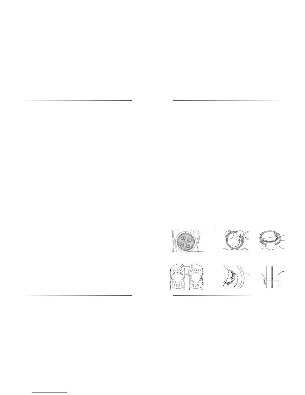
2.1 Um den Federring aus dem Pin auszufädeln, sollte kein Druck auf diesem lasten. Der Ring wird gedreht, bis das innere, gekröpfte Ende mit der Rundung am Pin
anliegt. Dann über die Kuppe des Pins drücken und weiterdrehen, bis der Ring ganz ausgefädelt ist. Festhalten! ( C ) ( D )
2.2 Um den Pin wieder zu schließen, muss er zunächst durch Druck von der Bindungsinnenseite her entlastet werden. Dann wird das gekröpfte Ende des Ringes in
das Loch eingefädelt und eingedreht. ( E ) ( F ) !!! Wichtig ist beim Einfädeln des Federringes, dass die gekröpfte Windung zur Bindung hin ausgerichtet ist.
2. Opening and closing of the pins
2.1 When taking out the lock ring from the pin, no pressure should be applied on it. The ring should be turned until the inside angled end with the curve is touching
the pin. Then press the point of the pin and keep turning until the ring is out completely. Be sure to hold on tight! (C) (D)
2.2 In order to close the pin again it first has to be realeased with pressure from the inside of the binding. Then the angled end of the ring is inserted into the hole and
turned. (E) (F) !!!It is important that the angled end points towards the binding while winding in the lock ring.
1. Montage der Bindung
Folgende Teile solltest Du bereit halten: Bindung, Disc (4x4), Schrauben. Beilagschrauben, Schraubenzieher und natürlich Dein Snowboard. Ziel Deiner Montage muß
es sein, die Fußposition zu zentrieren, Deinen individuellen Winkel und den richtigen Stance zu fixieren und “goofy” oder “regular” einzustellen.
Positionierung mit 4x4 Disc: Die asymmetrisch positionierten Bohrungen in der Disc ermöglichen die richtige Einstellung der Bindung durch Drehen der Disc um 180°.
Für eine Schuhgröße von 7,5 (US Größe) und darüber sollte die Disc so positioniert sein, daß die Bohrungen, welche am nächsten zur Kante der Disc sind, zur
Zehenseite des Boardes zeigen (Zeichnung). Für eine Schuhgröße kleiner als 7,5 (US Größe) sollten die Bohrungen, welche am nächsten zur Kante der Disc sind, zur
Fersenseite des Boards zeigen. ( A )
Einstellung des Stance für 4x4 Disc: Für die Adjustierung der Bindungsposition in der Längsrichtung des Boardes verwende die Bohrungen in Längsrichtung der Disc
in 10mm Abständen in Übereinstimmung mit den Board-Inserts.
Einstellung des Bindungswinkels: Deinen gewünschten Bindungswinkel stellst Du ein, indem die Gradzahl auf der Disc mit den Markierungspunkten auf dem Chassis
übereinstimmt. Bitte versichere Dich, daß alle Zähne der Disc mit den Zähnen des Chassis gut einrasten.
■ Beim Festziehen der Discschrauben halte die Disc fest und ziehe die Schrauben kreuzweise an. Versichere Dich, daß alle Schrauben fest sitzen.
BITTE VERWENDE NUR DIE BEIGELIEFERTEN SCHRAUBEN!
■
Die optimale Position der Bindung auf dem Board ist dann gegeben, wenn Dein Fuß richtig positioniert ist und nicht der Schuh. Als Faustregel gilt: gleicher Abstand
der Zehen und Ferse von der Boardkante.
■
Bitte beachte, daß die Temperatur den Sitz der Schrauben beeinflussen kann. Du solltest sicherheitshalber nach jedem Aufenthalt in der Wärme, also bevor Du in
die Kälte zurück zum Boarden gehst, die Schrauben nachziehen.
■
Bitte überprüfe Deine Bindung regelmäßig. Achte dabei besonders darauf, daß das Power Kabel in gutem Zustand ist und die Schrauben fest angezogen sind.
Die Chassis der Team Bindung sind asymmetrisch. Deshalb muss darauf Geachtet werden, dass die Bindungen mit den ausgewölbten Seitenwänden bzw. den Icons
im Zehenbereich zueinander montiert werden. ( B )
Diese Bindung ist auf werkzeuglose Verstellbarkeit ausgerichtet. Deshalb wird zunächst erklärt, wie die Pins zu öffnen sind. Diese halten alle Teile außer dem Hiback,
welcher entweder durch eine Flügel- oder Sechskantmutter fixiert wird. Mit der Flügelmutter bleibt die werkzeuglose Verstellung erhalten. Wem dies zu ungewöhnlich erscheint, der kann ohne weiteres die mitgelieferte Sechskantmuttern verwenden.
1.Mounting the Binding
You should have the following parts ready: Binding, Disk, screws (x 4), washers, screwdriver and of course your snowboard. The goal in mounting the binding is to
center the foot position, set your individual angle and adjust for Goofy or Regular stance.
Positioning the disk: The asymmetrically positioned holes in the disk allow the correct adjustment of the binding by turning the disk 180 degrees. For a shoe size of
7.5 (US size) or larger, the disk should be positioned so that the holes closest to the edge of the disk are pointing toward the toe side of the board (diagram).
Adjustment of the stance for disk: For the adjustment of the binding position lengthwise on the board, (nose to tail), use the coresponding lengthwise holes, spaced
at 10mm gaps, in accordance with the pre drilled, threaded board inserts.
Adjustment of the binding angle: You can set your desired binding angle by placing the degree number from the disk to corespond with the marker on the binding
chassis. Please ensure that the teeth from the disk are engaged well with the teeth from the binding chassis.
■
While tightening the disk screws, hold on to the disk and tighten the screws in a cross pattern. Be sure all screws are tight. PLEASE USE ONLY THE SCREWS PROVIDED.
■ The ideal position of the binding on the board is when your foot is positioned in the correct position, not the shoe position. Rule of thumb: The gap to the edge of the
board should be the same for the toe as it is for the heel.
■ Please bear in mind that temperature can affect the tightness of the screws. As a precaution you should always re-tighten the screws after the board has been in a
warm area and/or before going into the cold.
■ Please check the binding regularly, paying particular attention that the power cable is in good condition and the screws are tight.
The chassis of the team binding is asymmetric. Check the bindings have the buldged sidewalls and the icons facing each other. (B) This binding is set up for tooless
adjustability with the use of pins for easy adjustment. These hold all parts except for the highback which is attached with either a wing nut or a hex nut. With the wing
nut, the tooless adjustment stays the same. Those who find this too strange can use the hex nuts.
Nothes
Crans
Markierungspunkt
Crans
( B )
( A )
( E )
( C )
( F )
( D )
FLOW TEAM BINDING MANUAL
Page 3
3. Mounting of the ratchet straps
3.1 The front ratchet straps can be mounted in 2 different elongated slots. Should the front ratchet straps be twisted after adjusting the foot strap, it is recommended to mount these in the next elongated hole. !!!The sliding of the ratchet straps in the elongated holes is intended and allows for a certain amount of self adjustment.
3.2 Before the position of the back ratchet straps is changed the highback should be removed to create access to all positions in the upper row of holes.
3.3 The following sequence is suggested when the mounting points of the ratchet strap and the highback lie close to each other:
1. Remove the ratchet straps.
2. Remove the highback. (before opening the wing nut the safety ring has to be detached)
3. Position the pin for the ratchet straps.
4. Position the highback.
5. Bolt together the highbck.
6. Mount ratchet straps and close pin with the lock ring.
The order ensures free access to all the parts during the set up and should be followed when the position of the ratchet straps and the highback are close to each
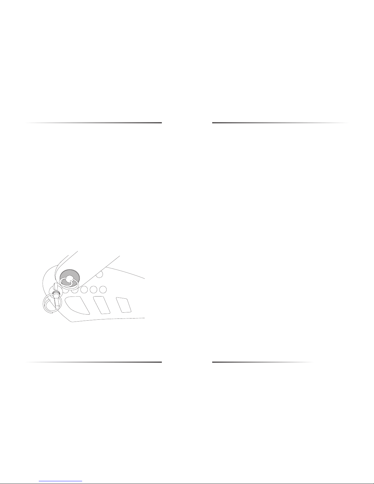
other. If there is enough space between them, the order is of course unimportant. Order (G)
!!!The metal insert which sits in the hole of the ratchet strap must definitely be re-attached; if not the fastening function of the lock ring is not ensured. (G)
3. Montage der Ratschenbänder
3.1 Die vorderen Ratschenbänder können in 2 verschiedenen Langlöchern montiert werden. Sollten die vorderen Ratschenbänder nach dem Einstellen der
Fußschlaufe verdreht sein, empfiehlt sich, diese im nächsten Langloch zu montieren.
!!! Das Gleiten der Ratschenbänder in den Langlöchern ist beabsichtigt und erlaubt diesen sich innerhalb des Einstellbereichess elbstständig anzupassen.
3.2 Bevor die Position der hinteren Ratschenbänder verändert wird, sollte der Hiback demontiert werden, um freien Zugang zu allen Positionen in der oberen
Lochreihe zu schaffen.
3.3 Folgende Reihenfolge ist sinnvoll, wenn die Montagepunkte des Ratschenbandes und des Hiback nahe beieinander liegen:
1. Ratschenband demontieren.
2. Hiback demontieren. (vor den Öffnen der Flügelschraube, muss der Sicherungsring gelöst werden)
3. Pin für Ratschenband positionieren.
4. Hiback positionieren.
5. Hiback verschrauben.
6. Ratschenband montieren und Pin mit Federring verschließen.
Diese Reihenfolge gewährleistet den ungehinderten Zugang zu allen Teilen innerhalb der Arbeitsstufen und sollte eingehalten werden, wenn die Positionen von Hiback
und Ratschenband nahe beieinander liegen. Ist zwischen diesen genug Abstand vorhanden, wird diese Reihenfolge natürlich unwichtig. Reihenfolge ( G )
!!! Das Metalinsert, welches in der Bohrung des Ratschenbandes sitzt, muss unbedingt wieder montiert werden, da sonst die Befestigungsfunktion des Federringes
nicht mehr gewährleistet ist. ( G )
( G )
FLOW TEAM BINDING MANUAL
Page 4
4. Montage des Highback und Einstellung des Vorlagewinkels.
4.1 Der Hiback kann innerhalb der unteren Lochreihe nach Belieben rotiert, oder an Schuhgrößen bis mindestens US 7.5 in der Länge angepasst werden.
!!! Die untere Lochreihe sollte eingehalten werden, um die korrekte Höhe der Fersenbrücke für die jeweilige Hibackgröße einzuhalten. Die Höhe der
Fersenbrücke kann über 3 Hibackgrößen variiert werden.
4.2 Die ideale Montagereihenfolge ist unter Punkt 1.3 beschrieben.
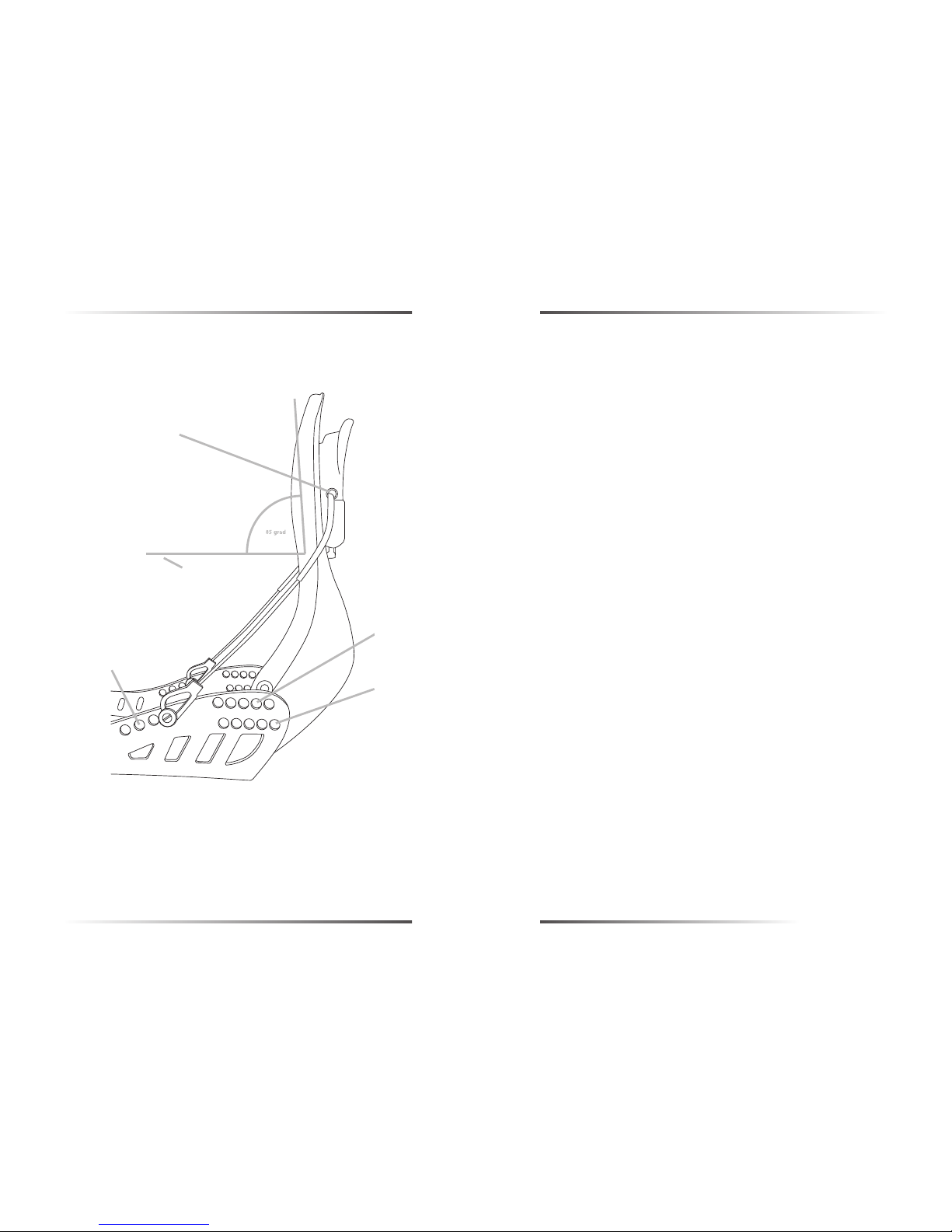
4.3 Um den Vorlagewinkel einzustellen, muss der Hiback wieder mit dem Chassis verschraubt, und die Mikroeinstellschraube im SnapLock auf die unterste Position
gedreht sein. Dann muss die Kabelposition gewählt werden, und der Kabelschuh wird mit dem Pin fixiert. Das Kabel sollte so positioniert werden, dass die
Kontaktfläche des Hiback in einem Winkel von ca. 85°zur Standfläche des Chassis steht, solange sich die Mikroeinstellschraube in unterster Position befindet.
Dies gewährleistet das Einschnappen des SnapLock auch bei minimaler Vorlageneinstellung. ( H )
4.4 Von hier aus wird die Vorlage der jeweiligen Fahrsituation mit Hilfe der Mikroeinstellschraube angepasst. Bewegt sich der Schlitten im SnapLock nach oben,
verändert sich der Vorlagewinkel in Richtung Toeside, nach unten, in Richtung Heelside.
!!! die Kabel müssen nicht symmetrisch angeordnet sein. Die Position kann auf jeder Seite frei gewählt werden, solange die Mindestvorlage dabei eingehalten wird.
4. Mounting of the highback and adjusting the forward lean angle.
4.1 The highback can be rotated as desired using the lower row of holes or can be adjusted lengthwise to suit the boot size.
!!!The lower hole row should be used so that the correct height of the heel bridge for each highback size is met. The height of the heel bridge can be varied for
3 highback sizes.
4.2 The ideal mounting order is described under 3.3
4.3 In order to adjust the forward lean angle, the highback has to be reattached to the chassis and the micro adjust screw in the snap lock has to be turned to the
lowest position. The cable position is then selected and the cable must be attached with the pin. The cable should be positioned so the contact area of the highback is at an angle of 85 degrees towards the standing area of the chassis as long as the micro-adjustment screw is in the lowest position. This ensures the
locking of the snap lock even at a minimum of forward lean angle. (H)
4.4 From here the forward lean of each riding situation is adjusted with the help of the micro adjust screw. If the guide moves up in the snap lock the forward lean
angle changes towards the toe side direction and if it moves down in the snap lock then the angle is changed towards the heel side.
( H )
FLOW TEAM BINDING MANUAL
 Loading...