

Flottweg TRICANTER Z 8E Operating Instructions Manual

Operating Instructions
RICANTER® Z 8E
T
Machine number: 019.026.21
Project number: P32825
Revision 1
Original operating instructions
Ed
ition: 2018-02-01
© Copyright by Flottweg SE. All rights reserved.
The copyright of this document remains with Flottweg SE.
This document contains specifications and technical drawings and
must therefore neither completely nor partially be copied or passed on
to third persons.
®
Flottweg
Registered trademark in different countries.
Subject to alterations. Errors excepted.

Deutsche Bank, München F
IBAN: DE25 7007 0010 0870 2110 00 Amtsgericht Landshut HRB 8839 Industriestr. 6 - 8 Telefax: +49 8741 301-300
BIC: DEUT DE MM XXX Konto-Nr. 8 702 110 00 84137 Vilsbiburg E-Mail: mail@flottweg.com
Vorsitzender des Aufsichtsrats: Deutschland http://www.flottweg.com
Bayerische Landesbank, München Peter Bruckmayer
IBAN: DE06 7005 0000 0000 0301 76 Flottweg SE VAT-Id-No. DE811 140 623
BIC: BYLA DE MM XXX Konto-Nr. 30 176 Vorstand: Postfach 11 60
Fritz Colesan (Sprecher) 84131 Vilsbiburg
Flottweg
Commerzbank, Regensburg Peter Frankfurter Deutschland
IBAN: DE62 7508 0003 0195 6760 00 Karl-Heinz Grebisz
BIC: DRES DE FF 750 Konto-Nr. 0195676000 Dr. Christoph Heynen
lottweg SE Flottweg SE Telefon: +49 8741 301-0

UK
Declaration of Incorporation
in accordance with the EC Machinery Directive 2006/42/EC
Herewith we declare that the machine for the separation of solid/liquid mixtures, at the time
of delivery
Machine no. 019.026.21
Machine type Z8E-4/441
meets all the applicable requirements of the afore mentioned Directive as well as the
following additional pertinent regulations:
2014/30/EU, 2014/35/EU
The scope of delivery is exclusively intended for incorporation with other
components/machines into a system. Acceptance is therefore prohibited until it has been
determined that this system corresponds to the requirements of the Directives listed above.
Applied harmonized standards:
DIN EN 60204-1 DIN EN 12547
DIN EN ISO 13849-1 DIN EN ISO 12100
The Documentation department of Flottweg SE is authorized to compile the technical
documentation pursuant to the Machinery Directive.
Vilsbiburg, 06.03.2017
Flottweg SE
Dr. Christoph Heynen i.V. Dr. Roland Merkl
Executive Vice President Quality Manager
Engineering and Technology
Deutsche Bank, München F
IBAN: DE25 7007 0010 0870 2110 00 Amtsgericht Landshut HRB 8839 Industriestr. 6 - 8 Telefax: +49 8741 301-300
BIC: DEUT DE MM XXX Konto-Nr. 8 702 110 00 84137 Vilsbiburg E-Mail: mail@flottweg.com
Vorsitzender des Aufsichtsrats: Deutschland http://www.flottweg.com
2016-09-05
Bayerische Landesbank, München Peter Bruckmayer
IBAN: DE06 7005 0000 0000 0301 76 Flottweg SE VAT-Id-No. DE 811 140 623
BIC: BYLA DE MM XXX Konto-Nr. 30 176 Vorstand: Postfach 11 60
Fritz Colesan (Sprecher) 84131 Vilsbiburg
Commerzbank, Regensburg Peter Frankfurter Deutschland
IBAN: DE62 7508 0003 0195 6760 00 Karl-Heinz Grebisz
BIC: DRES DE FF 750 Konto-Nr. 0195676000 Dr. Christoph Heynen
lottweg SE Flottweg SE Telefon: +49 8741 301-0

OPERATING INSTRUCTIONS
for Flottweg TRICANTER® with SIMP-DRIVE®
1. General
1.1 Description of your centrifuge
1.2 Safety
1.3 Technical data
2. Operation
2.1 Transport, mounting and first commissioning
2.2 Operation
2.3 Cleaning
2.4 Operation of variable impeller
3. Lubrication and inspection
368.0201.00-Uk
3
.1 Lubrication intervals
3.2 Lubrication instructions
3.3 Maintenance plan
3.4 Description of maintenance procedures
3.5 Checking of the safety functions
4. Operating troubles
4.1 Safety instructions on operational breakdown
4.2 Trouble shooting
5. Tables and diagrams
5.1 Phase separation disc diameter
6. Appendix
- S
IMP-CONTROL®
- SIMP-DRIVE®
- Motor
- Centrifuge control sheet
7. Accessories
- Differential and bowl speed measuring
- Temperature monitoring of the centrifuge
- Vibration monitoring
- Multi-turn actuator
8. Disposal
8.1 Disposal
9. Certificates
Uk-0_I-Getr-0_040107-Pre Uk-0_Inhalt_110313-Pre
Flottweg

1.
GENERAL
Uk1-allg_030107–Pre
Flottweg
Function 1.1/1
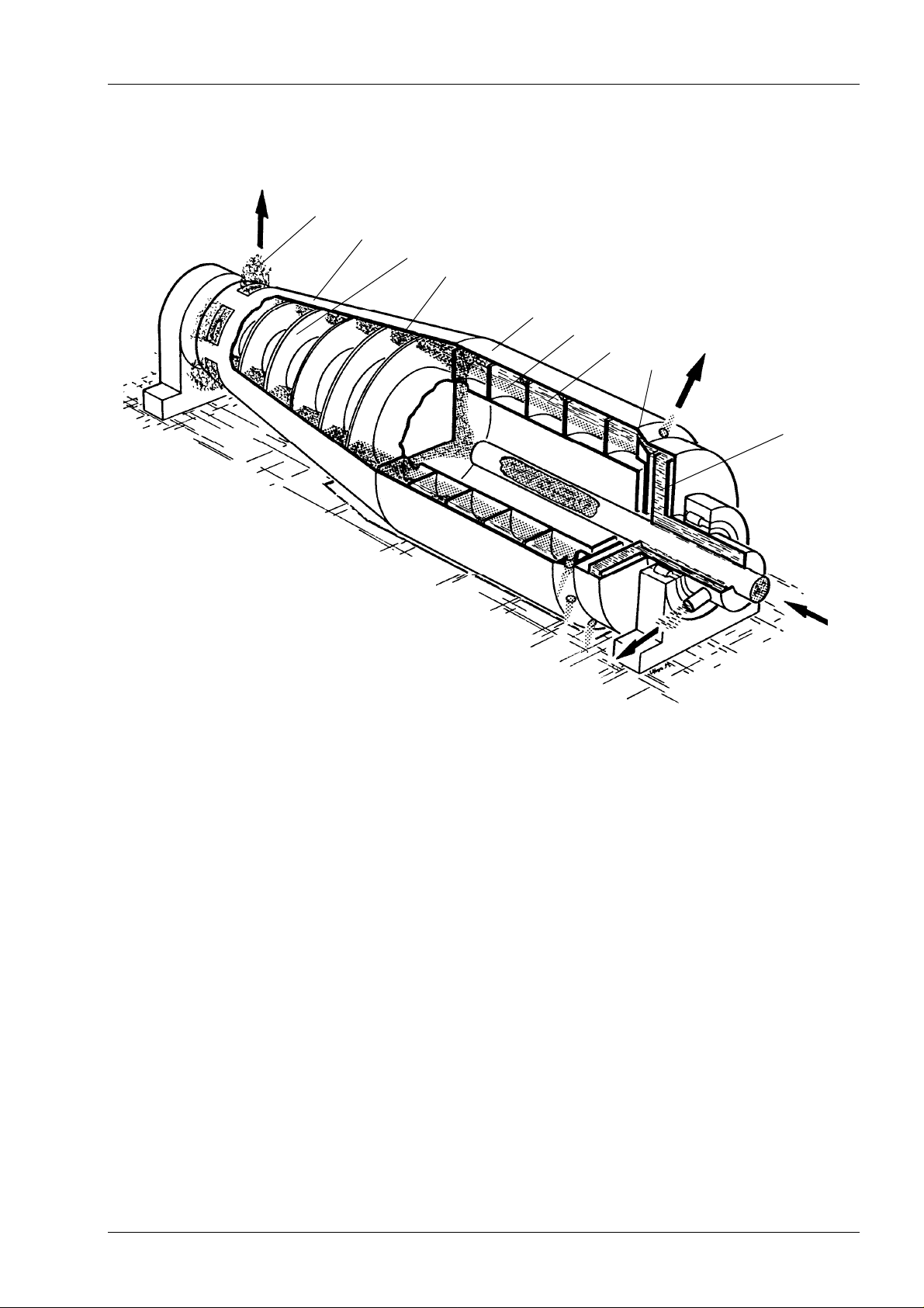
The medium to be separated is fed into the decanter through the central feed pipe (1).
The denser solids settle against the bowl wall (2) under the influence of the centrifugal
force.
The two liquid phases (3,4) , which have different densities, form hollow cylinders, the
light phase the inner one, the heavy phase the outer one.
The thickness of the individual liquid rings is determined by the adjustment of the
overflow weir (5) and the variable impeller (6).
The solids deposited on the bowl wall (7) are transported towards the conical end of the
bowl (9) by the conveyor scroll (8) to the discharge ports (10) and discharged into the
solids housing.
10
9
8
7
2
3
4
5
6
1
Uk1_1_1_3x8-4_280689_Pre
Flottweg

Function 1.1/2
The moisture content of the discharged solids and the purity of the liquid can be adapted:
a) by changing the separation line between the two liquids by means of the variable
impeller and a wide selection of phase separation disks:
- lower moisture content of the solids by chosing a larger diameter of the phase
separation disk and thereby increasing the drainage zone
- optimum quality of the heavy phase by maximum difference between the
impeller diameter and the diameter of the phase separation disk
- optimum quality of the light phase by minimum difference between the impeller
diameter and the diameter of the phase separation disk
b) by changing the bowl speed:
- the finer the solids, the higher the bowl speed necessary for satisfactory
separation results.
c) by changing the scroll differential speed:
- the lower the desired moisture content of the discharged solids,
the lower you set the differential speed.
- the higher the solids content in the inlet,
the higher the required differential speed.
Note: The optimum machine setting can only be determined by careful testing.
Uk1_1_2_3x8-4_260689_pre
Flottweg
Safety instructions 1.2/1
WARNING
Please pay careful attention to the following instructions,
for your own safety!
Safety information
The machine has been tested for operating safety and function at the manufacturing
plant before delivery.
Nevertheless incorrect operation or misuse may cause danger for
- life and health of the operating personnel
- the machine and other goods of the operator or third persons.
planation of signs
Ex
In the following manual special risks are marked as follows:
This sign describes danger situations which will result in
serious and worst injuries up to death in case of non-
DANGER
observance of the instructions.
This sign describes danger situations which may result in
serious and worst injuries up to death in case of nonobservance of the instructions.
CAUTION
This sign describes situations which may cause minor
injuries.
Moreover, it is used as a warning of material or property
damage.
Uk1_2_3x8_210916– Pre-vi-schl
Flottweg

Safety instructions 1.2/2
Safety checks
- Before every start-up check protective installations for existence and function.
- Carry out all checks as stated in section “Maintenance plan“ conscientiously.
- Observe all testing terms required by law unconditionally!
(detailed explanations, see also section “Maintenance plan“)
Responsibilities
The range of responsibility of F
detailed information about the services to be rendered in the order and/or in the
confirmation of order.
This includes for example
- components such as centrifuges with drive, electrical switchgear, facility parts
(pumps, conveyor, piping, fittings) ....
- services such as installation, commissioning, staff training, cabling ...
lottweg only covers the scope of supply. You will find
Authorized operation
The machine serves exclusively for the separation of liquids and solids and has been
specially designed for the medium stated in the technical data.
Do not use for processing or cleaning:
- medium with higher density or higher/lower temperature than specified on the
machine plate
- medium with metallic impurities
- medium with corrosive effect on the used materials
- medium which is easily inflammable or injurious to health
Unauthorized modifications or changes of the machine are forbidden for safety reasons.
The data stated on the machine plate must not be exceeded, as otherwise the operating
safety of the machine is not guaranteed.
The machine is only to be operated in a technically perfect working condition.
Defects have to be eliminated before starting up again.
Each operation of the machine/facility which does not conform with the stated admissible
terms and safety regulations is considered as not authorized and is thus inadmissible.
Flottweg hereby draws your attention to the fact that independent changes to the source
code of the controller, even minor ones, can lead to significant unforeseeable
malfunctions and damage to the machine and its surroundings.
Changes to or removal of copyright or licensing references in the source code without
the prior approval of Flottweg may be subject to criminal and civil penalties.
Moreover, when using source code, please note the fundamental conditions of German
copyright law.
Uk1_2_3x8_210916– Pre-vi-schl
Flottweg
Safety instructions 1.2/3
WARNING
WARNING
Danger at the machine
Rotating parts may bruise or cut off fingers and hands.
Operate centrifuge only with properly mounted safety
The main risk at the machine is the fast rotating rotor and its drive unit.
Rotor, belt drive and motor may bruise or cut off fingers and hands.
Therefore hood and covers must not be removed before the rotor is at standstill.
As a matter of principle, before maintenance and dismounting work, make sure that the
rotor stands still and is secured against restarting.
DANGER
covers!
The solids are centrifuged downwards out of the solids
housing with great power.
Danger of injury to fingers and hands.
Never put your hand into it!
Always take solids samples with suitable tool.
The solids chute has to be lead closed up to the conveyor or collecting tank.
Thereby sound emission is reduced and ejected parts (kernels, stones, etc.) are
prevented from rebounding from the floor and thus causing injuries.
CAUTION
After two hours:
- Either switch the bowl drive off
- or reduce the bowl speed to 30%
- or flush the decanter for cooling
With hydraulic drives oil may squirt out under high pressure
due to damages at individual components.
This may cause injuries especially to the eyes and
poisoning.
In case of contact with skin and eyes take measures as
stated in the provided safety data sheet.
During operation without product the temperature of the
centrifuge can increase inadmissibly high. Therefore the
centrifuge may be operated without product for maximum
two hours.
Uk1_2_3x8_210916– Pre-vi-schl
Flottweg

Safety instructions 1.2/4
Measures in an emergency
In the event of an emergency the machine/facility is to be stopped immediately.
In case of fire, the operating company must provide for the immediate disconnection of
power and other firefighting measures. Fast-running centrifuges can generate large
amounts of heat in cases of extreme damage, igniting flammable substances.
After an emergency shutdown or a power failure, the machine may only be restarted by
hand. An automatic restart is not permitted.
The defects have to be eliminated before starting up again.
Maintenance or dismounting works
Maintenance or dismounting work may only be performed by the operator according to
he instructions and up to the extent stated in the operating instructions. Other
t
maintenance and repair work than described in the operating instructions is only to be
performed by persons which are especially authorised by Flottweg.
No changes, attachments or modifications are allowed to be made to the machine
without the express approval of Flottweg . Original spare parts and accessories
approved by Flottweg will aid safety. The usage of other parts renders void any liability
for the consequences.
Water endangering medium or fuel, if flowing out at maintenance work or through
leakages, must by no means reach the ground or the sewerage system. When
exchanging oil or removing excessive or worn grease, pay special attention to
environmental protection and professional waste disposal.
Substances are to be bound with suitable absorbents immediately.
No objects must be deposited on the machine. They might slip below the protective
covers, be caught by rotating parts and thrown off.
Before maintenance and dismounting work always
- switch off machine
- wait until machine comes to a complete standstill
(depending on the type up to 45 minutes)
- check if rotor stands still (e.g. fan blade at the main motor)
- secure against restarting (e.g. padlocks at the main switch)
Authorized operators
Juveniles under 18 years are not allowed to operate the machine.
ll operating and maintenance work is only to be performed under observance of the
A
pertinent laws and general directions.
The machine may only be operated by persons who have read and also understood the
operating instructions and who are familiar with the whole facility.
Work at electrical parts and wirings is only to be performed by trained electrical
specialists under observance of the pertinent laws and general directions.
The plant has to be secured against unauthorized operation by a key-operated
switch.
Noise emission
The accoustic power level of a machine cannot be stated generally, as it differs
ccording to the size and adjusted speed of the respective machine.
a
Exact values can be gathered from the sound level table.
Uk1_2_3x8_210916– Pre-vi-schl
Flottweg

Safety instructions 1.2/5
Protective equipment according to instructions for accident prevention
Especially
during operation
- non-skidding footwear
- ear protection from 85 dB(A)
during maintenance and repair work
- safety helmet
- gloves
- safety boots
e of installation
Plac
The place of installation must comply with the conditions defined in the planning
documents.
Exclusion of liability
The operating company is responsible for all hazards that result on site, for example,
hazards that:
- Are inherent to the product or cleaning agents
- Are due to the setup or surroundings of the centrifuge
- Are due to lack of expertise or authorization on the part of personnel
- Can result from media supply (electricity, water, compressed air, etc.)
- Are due to system parts not approved by Flottweg
- Occur due to lack of maintenance and repair.
ety and warning signs
Saf
The machine plate states all characteristic data of the centrifuge and is mounted to the
rotor base.
Made in Germany
no.Nr.typeTyp
year of manufacturingBaujahr
-
1
zul. Trommeldrehzahl
zul. Sedimentdichte
min./max. Produkttemp.
Uk1_2_3x8_210916– Pre-vi-schl
max. bowl speed
max. sediment density
min./max. product temperature
min
g/dm
k
°C
barmax. housing pressurezul. Gehäusedruck
kg
3
Flottweg
Safety instructions 1.2/6
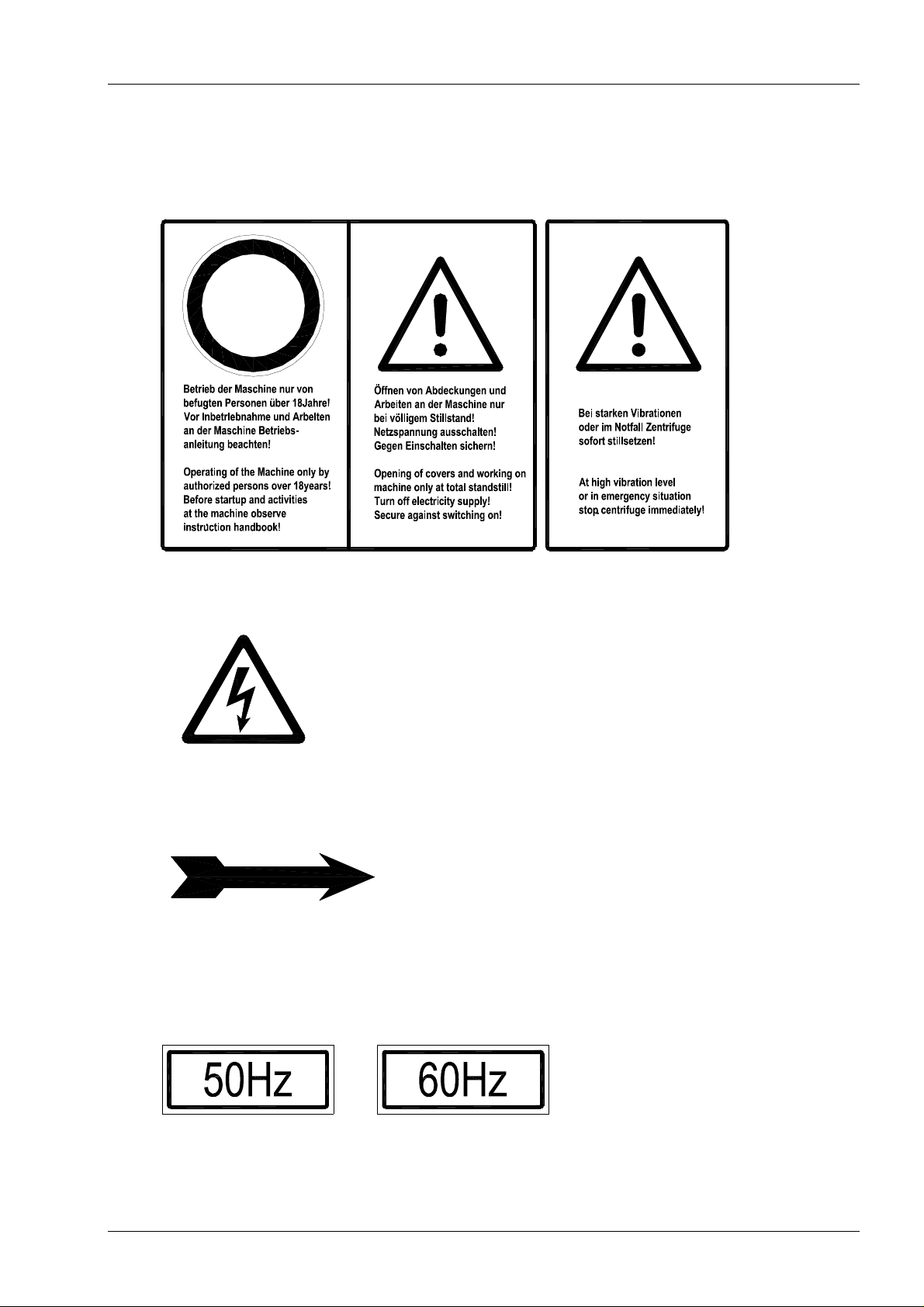
Safety and warning signs
The warning signs for special hazards are next to the machine plate.
The flash of lightning warns against dangerous voltage. Work on these parts must only
be carried out by electrical specialists.
The rotation arrow shows the correct direction of rotation of the motor and the bowl.
The wrong direction of rotation leads to faulty functions of the centrifuge and can cause
overload of components.
Frequency label on the motor
The belt drive is dimensioned such that by means of the stated frequency the operating
speed is reached. Exceeding this frequency leads to exceeding the admissible bowl
speed.
Uk1_2_3x8_210916– Pre-vi-schl
Flottweg

Technical Data 1.3
Flottweg-TRICANTER® Z 8E-4/441 Machine no.: 019.026.21
1. Centrifuge layout for
Separation and preparation of used cooking oil
Base of suspension watery, pH = 4...10
Admissible cleaning agent see 2.3 rinsing
2. Rotor
Max. speed 2650 min-1
Max. sediment density 1.5 g/cm³
Bowl inside diameter 770 mm
Discharge diameter 465 mm
Min./max. product temperature 0/100° C
3. Product touched material:
Bowl 1.4468 - TI-QUA-0031
1.4463 – TI-QUA-0002
Other parts 1.4463 / 1.4408 / 1.4571
Seals FKM; SIC
Scroll wear protection tungsten carbide
4. Adjustments:
Bowl speed ...2650 min-1
oll differential speed -1.5...-29.6 min-1
Scr
Mode of operation lagging
Diameter impeller disc 420...532 mm
Diameter of phase separation disc Ø 471 mm
5. Drive:
Type SIMP-DRIVE®
Gear type SP 3.11
Ratio 1:48.696
Bowl drive motor 404/5T
performance 100 HP
rated speed 1800 min
voltage / frequency 46
0 V / 60 Hz
-1
max.adm.frequency with converter operation 60 Hz
Ex – protection class Cla.1 Div.2
Scroll drive motor 284T
performance 25 HP
rated speed 1800 min
voltage / frequency 460 V / 60 Hz
-1
max.adm.frequency with converter operation 60 Hz
Ex – protection class Cla.1 Div.2
6. Dimensions and weights:
Installation plan C 367.0200.40
7. Sound emission: see sound ranging data sheet
8. Lubricants: see sect. 3
Uk1_3_Z8E_Simp_180412-Li
Flottweg

2.
OPERATION
Uk2-allg_030107–Pre
Flottweg

Transport, mounting and first commissioning 2.1/1
Transport
During transport of the centrifuge observe the regulations for safety at work.
Lifting of the centrifuge is only allowed with checked lifting devices.
For weight and suspension points refer to the installation plan, which is included in the
planning documents.
Mounting and first commissioning
The proper control of the installation and the optimisation of the adjustment of the
machine and plant during commissioning is condition for a safe and economic operation.
Attention has to be paid to the following rules for the first commissioning and safety.
Authorised persons
CAUTION
Before the first commissioning the centrifuge has to be checked for proper installation,
equipment and readiness for operation by an authorised technical expert. (Instructed)
operational personnel which is working by means of the operating instructions is
considered as not authorised.
Therefore we recommend that a Flottweg-technician will perform the installation, first
commissioning, optimisation of the adjustment and instruction of the personnel.
Check before commissioning (by an authorised technical expert)
1. Location
2. Acceptability of means of transport
3. Check if transportation locks are removed (see 2.1/2)
4. Connections to the machine
5. Signs on the machine
6. Transport systems of liquids and solids
7. Does the product correspond to the specification
8. Function of the safety installations (belt guard, covers)
9. Sense of rotation of the motors
10. Function of the limit value control
11. Switching sequence, locking
12. Function of the central lubrication system (see 3.2/1)
13. Inertisation (if existing)
Faulty installation and commissioning of the centrifuge
may cause dangerous operating conditions, which will
result in severe damages and danger to persons.
The first commissioning has to be executed by an
authorised technical expert.
Optimisation during commissioning (by an authorised technical expert)
- Optimum adjustment of the machine (parameter)
- Observation regarding product deposits and optimisation
of the rinsing program (intervals, time, quantity)
- Observation regarding wear/corrosion
Uk-2_1_1-3x8_Trans_100407-Pre-Vi-sw
Flottweg

Transport, mounting and first commissioning 2.1/2
Transportation lock
The transportation locks block the rotor and relieve the rotor bearings from
shocks during transportation.
Danger of machine damage.
CAUTION
CAUTION
Demounting:
- remove all 4 set screws (red).
Note: Keep set screws!
Remove transportation locks before start-up.
Danger of machine damage.
For transportation of the machine, remount
transportation locks.
Mounting
- Before each transportation of the machine screw in set screws (red) and tighten with
a torque of 10 Nm (8 ftlb).
Uk_2_1_2-C7E_Trans_300112-Pre
Flottweg

Operation 2.2
1. Check before starting:
- feed pump / flocculant pump must not start when
centrifuge is not in operation
2. Start centrifuge
3. After starting
- centrifuge at full speed: start feed pump
- for suspensions with amorphous solids particles
or
very fine particles (several µ): raise decanter slowly
(10-20 min.) to full throughput rate
4. During operation
- check main bearing temperature (max. 130°C) after one hour
5. Stopping the centrifuge
- stop feed / flocculant supply
- feed water until effluent is clear
- clean centrifuge (see section "Cleaning")
- stop centrifuge
6. After stop
- mainswitch "OFF"
2_2_3x8_221001
Flottweg

Cleaning 2.3
1. Thoroughly clean the decanter immediately after stopping the supply of feed
material and before stopping the motor.
Max. water temperature 80° C.
Water consumption and flushing periods: depending on product
Note: If the decanter is not cleaned as required, restarting will
be complicated, especially after storage periods, due to
product deposits.
2. Cleaning procedures
2.1 Cleaning the bowl interior and the scroll (15 min)
- stop feed / flocculant introduction
- feed water through feed pipe and flush machine
- operate skimmer between min. and max. diameter several times:
at min. diameter liquid will flow through solids discharge openings
after some time and flush the solids housing
- as soon as effluent is clear water:
turn skimmer to max. diameter, stop supply,
turn off decanter and wait until rotor stops,
adjust skimmer to standard diameter
Note: After turning off the decanter, close centrate shut off valve, if centrate is
conveyed to a rising drain pipe without pump via the skimmer, otherwise main
bearings may be flooded by return flow of the head of liquid to the skimmer.
2.2 Flushing skimmer chamber via centrate line
- at 1/2 speed (1st motor step or with rotor slowing down)
introduce water until it flows over at the solids discharge side
- repeat several times if required
- switch off decanter
Uk2_3-3x8_430_280689-Pre
Flottweg
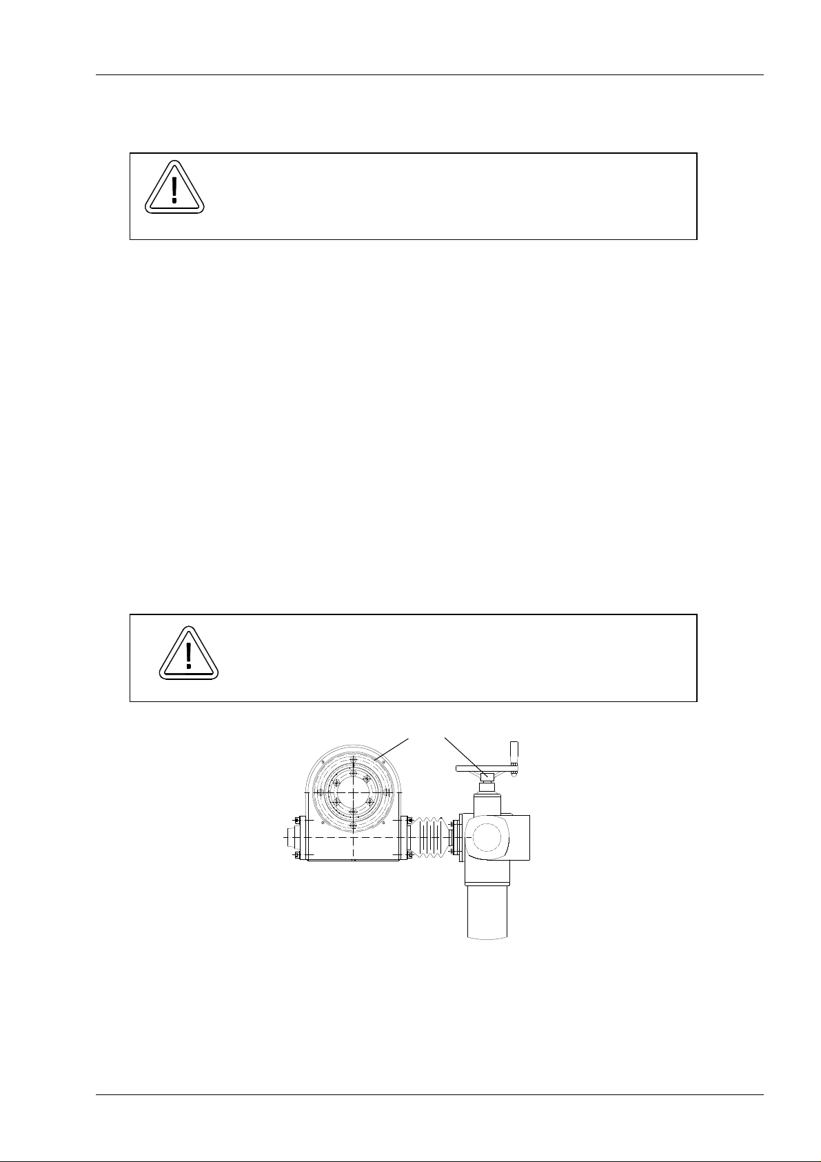
Operation of the variable impeller disc 2.4/1
2 1
With the variable impeller disc, the pool depth (weir diameter) can be adjusted infinitely.
The pressure of the discharged centrate must not
exceed 2 bar, otherwise danger of damage to the impeller
CAUTION
Adjustment of the impeller disc
The adjustment of the impeller diameter is allowed at standstill as well as during
operation of the machine.
The desired value can be set at the switchboard.
The adjusted impeller diameter (2) can also be read at the machine.
For manual adjustment, first push the button in the centre of the handwheel (1).
Note: If the paring diameter is increased after a longer operation with small
diameter, adjust the paring disc slowly and with running machine,
because of possible solids deposits, in order to pare off the solids.
If the impeller device can not be adjusted, demount actuator and impeller disc and clean
it (see maintenance manual).
Parametrization of remote impeller disc adjustment
Parametrize the remote impeller disc adjustment upon initial commissioning or when the
actuator has been disconnected from the rotor.
device.
Danger of damage to the actuator and the impeller system.
Never turn the handwheel on the actuator while the machine
is turned off. Endpoints will be lost!
CAUTION
Uk2_4_auma_210217-Li
Flottweg
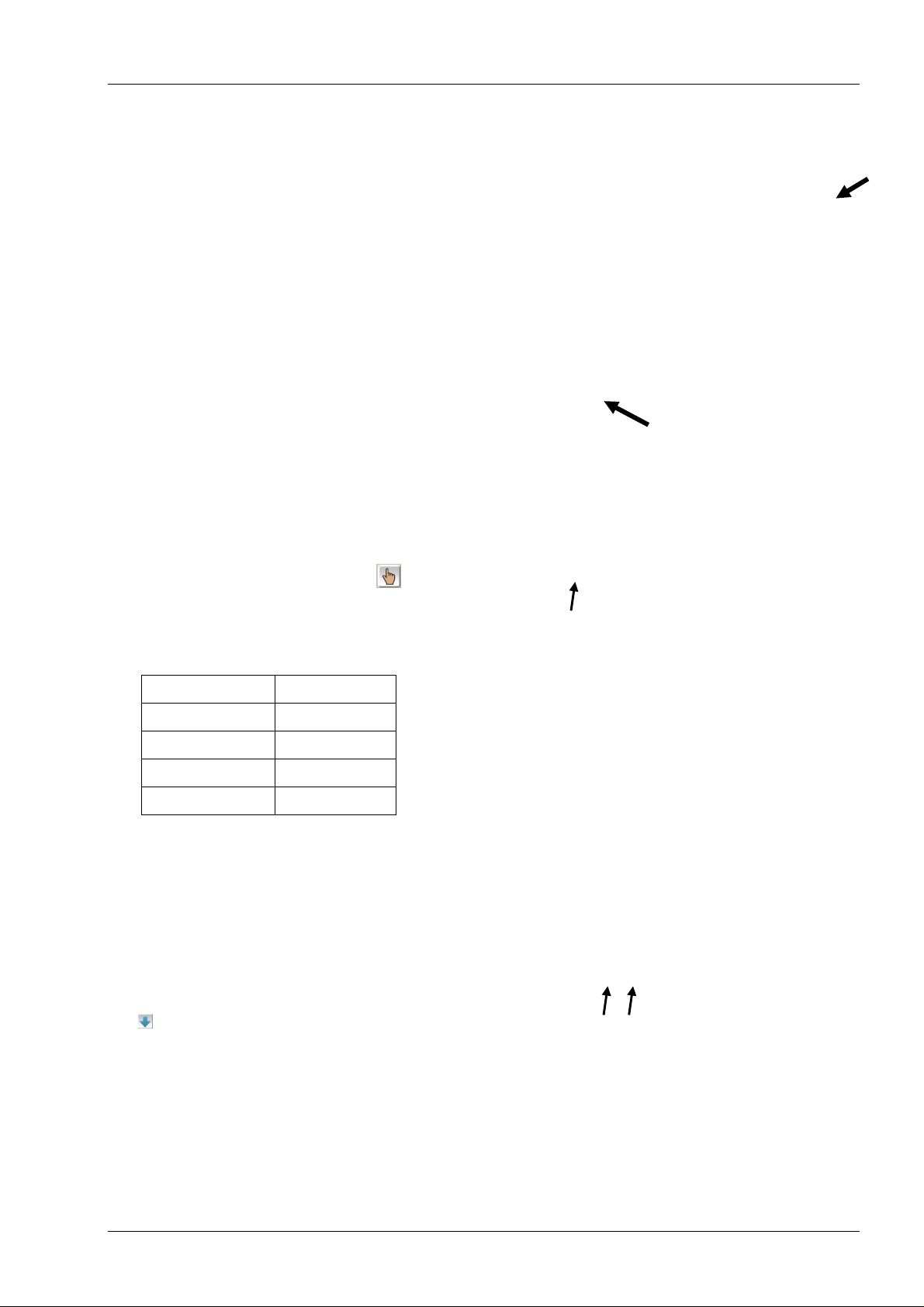
Operation of the variable impeller disc 2.4/2
1. Click on the bowl motor in Touch Control.
2. The “Bowl” window will appear.
3. Click on the “Parameter” button.
4. In the “Decanter” tab, click on the “Impeller
disc” tab
5. Switch to manual operation.
Click on the button until the symbol
appears.
6. Move the impeller disc into “centre position”
using the handwheel on the actuator.
Z3E: 180 mm S3E: 130 mm
Z4E: 250 mm S4E: 225 mm
Z5E: 320 mm S6E: 320 mm
Z6E: 400 mm
Z8E: 470 mm
7. Switch on the motor circuit breaker of the
actuator. Always switch off the motor circuit
breaker when servicing the actuator.
8. Test sense of rotation
Impeller diameter increases
Impeller diameter decreases
Uk2_4_auma_210217-Li
Flottweg

Operation of the variable impeller disc 2.4/3
The table in the “Impeller disc” tab shows the “Input”
and “Output” columns.
Input is an integral value (integer) in the range
between 0 and 27,648; it corresponds to
the 4-20 mA range of the potentiometer.
Output is the impeller disc diameter.
• The fields (grey) displaying the current value are
shown on top.
• The rows below contain fields (white) in which
the values for the control characteristic are
entered.
Determining the values
1. Demount the cover of the remote impeller disc
adjustment actuator by loosening the 4 screws.
2. Turn the handwheel on the actuator to minimum
impeller disc diameter.
3. Adjust the adjusting screw (2) until the current
value in Touch Control shows approx. 0.
4. In the top row of the input fields (white), enter
the minimum impeller disc diameter in the
“Output” column; then enter the current “Input”
value in the top row of the “Input” column.
5. Turn the handwheel on the actuator to
maximum impeller disc diameter.
6. Adjust the adjusting screw (1) until the current
value in Touch Control shows approx. 25000.
7. In the bottom row of the input fields (white),
enter the maximum impeller disc diameter in
the “Output” column; then enter the current
“Input” value in the bottom row of the “Input”
column.
8. Test setting.
Use the arrow buttons to select the minimum
impeller diameter (input value has to be 0).
Use the arrow buttons to select the maximum
impeller diameter (input value has to be 25000).
If different values are shown, repeat
steps 2 to 7.
1
2
Uk2_4_auma_210217-Li
Flottweg
Operation of the variable impeller disc 2.4/4
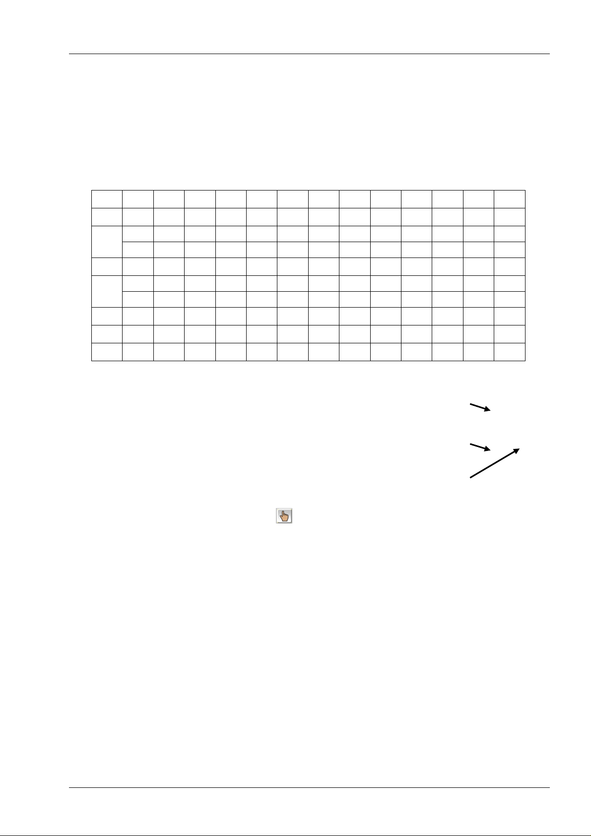
9. Input of impeller disc positions
The impeller disc intervals have to be defined by the user. A total of ten intermediate points
can be stored on the PLC for remote adjustment. The adjustment begins with the minimum
impeller disc diameter.
The table shows the impeller disc diameters marked on the machine.
Values without brackets should be used as intermediate points.
Z3E 160 165 170 175 180 185 190 195 200 205
Z4E 220
Z5E
(345)
Z6E 358 360
Z8E
S3E 115 120 125 130 135 138 140 143 145 146
S4E 200 205 210 215 220 225
S6E 295 300 305 310
280
420
485
(225)
(285)
350
(425)
(490) (495)
230 235 240 245 250 255 260
290
(355)
(365)
430
(295)
360 365
370
(435)
500
300
(305)
(375)
440
(505) (510)
(315)
380 390 400
(445)
320 325 330 335 340 346
310
450
515
(230)
(315)
(455)
(520) (525) (530)
235 240 245 248
320
(410)
460
(265)
(325)
420 430 440 450
(465)
270
330
470
532
Adjust the impeller disc diameter using the
handwheel on the actuator.
Enter the impeller disc diameter in “Output” (3),
then enter the current input value (4) in the
“Input” column (5).
10. After completing the entries, click the button
to switch to automatic operation .
(275)
(335)
(475) (480)
280
340
4
5
3
Uk2_4_auma_210217-Li
Flottweg

3.
LUBRICATION
AND
INSPECTION
Uk3-allg_030107–Pre
Flottweg
Lubrication diagram 3.1/1
B
C
A
A
point
Lubricating
Oil-air
unit
A
B
C
Electric
motors
Gear
Product temperature ≤ 80°C
without solvent
or
Product temperature ≤ 50°C
with solvent
Interval time 2 minutes (adjust rotary switch to position 2)
Empty residual-oil tanks always after refilling lubrication oil
Attention: dispose of oil professionally!
Scroll bearing
every 3 months 30 strokes
with manual grease gun
Scroll bearing
every 3 months 80 strokes
with manual grease gun
For motors with relubrication system
(Attention: 2 greasing points)
Oil change3 every 6 months according to instructions
(First change after 500 operating hours)
Product temperature > 80°C
without solvent
or
Product temperature > 50°C
with solvent
Scroll bearing
every 1 month 30 strokes
with manual grease gun
Scroll bearing
every 1 month 80 strokes
with manual grease gun
Lubricant
AGRIFARM
STOU
MC SAE
10W-403
Klüber
Catenera
KSB 8
Klüber
Catenera
KSB 8
refer to
motor label12
Klübersynth
UH1 6-100
Lubricant
quantity
1,1 liter /
100 hours
60 g / interval section 3.2/2
160 g /
interval
refer to
motor label
5 liter /
change
Further
hints
section 3.2/1
section 3.2/2
see appendix
1
alternative Fuchs Renolit HLT 2
2
Uk3_1_1-Z8E_Oel_Luft_220814-Li
lithium complex soap/mineral oil grease e.g. Flottweg HG
3
Oil must only be filled with a filter pump (mesh width ≤10µm)
1
Flottweg

Lubricants 3.1/2
Oil for Oil-air lubrication
Manufacturer Type Specification
Fuchs AGRIFARM STOU MC SAE 10W-40 STOU (Super Tractor Oil Universal)
Castrol Hyspin AWS 100 HLP (DIN 51524)
Alpha SP 100 CLP (DIN 51517)
Lukoil VERSO MOTOR 10W-40 STOU (Super Tractor Oil Universal)
GEYSER ST 100 HLP (DIN 51524)
STEELO HST 100 CLP (DIN 51517)
Shell Shell Tellus 100 HLP (DIN 51524)
Shell Omala 100 CLP (DIN 51517)
Spirax S4 TX 10W-40 STOU (Super Tractor Oil Universal)
Mobil Mobilgear 627 CLP (DIN 51517)
Mobil Agri Extra 10W-40 STOU (Super Tractor Oil Universal)
Klüber Klüberoil 4 UH1-100N NSF-H1 (food grade oil)
Uk-3_1_2_Oel_Luft_060616-Li/Vi
Flottweg
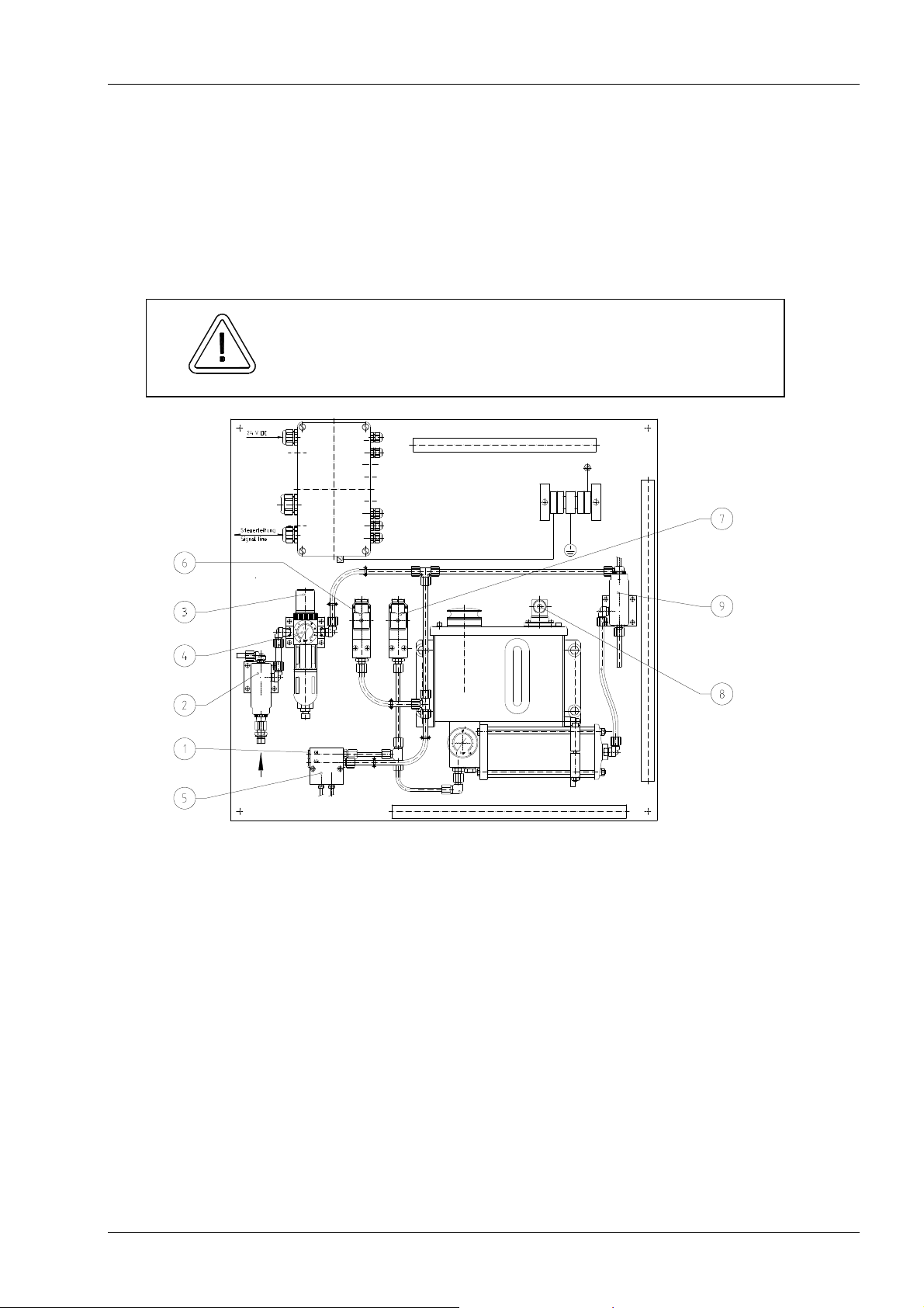
Lubrication instruction 3.2/1-1
Oil-air lubrication
1. Function
Both main bearings are supplied by a separate oil-air-lubrication system. After expiration
of the adjusted interval, oil is conveyed through the piston pump to the dosing unit and
from there delivered to the steady passing compressed air. Fluid drops are dispersed
streakily by a steady air flow and conveyed to the greasing points. The oil remains in the
friction point, the air escapes almost oilfree outside.
Make sure that the lubrication starts before the centrifuge is
started and only stops after the rotor has come to a
CAUTION
2. Adjustments
Pause time
The interval is adjusted at the switch board.
Set value: see sect. 3.1
Air pressure
Adjust air pressure at the control valve (3) to 4.5...5 bar by handwheel.
Pressure switch "Air"
Adjust limit value at the pressure switch (6) to 4 bar with
adjusting screw on the top side.
Pressure switch "Oil"
The limit value at the pressure switch (7) is pre-adjusted to 13 bar.
Air flow
Always turn in adjusting screws on the top of the distributor (5)
completely (=minimum air quantity)
standstill.
Uk3_2_1-3x8_Oel_Luft_Ex_1_221208_Pre
Flottweg
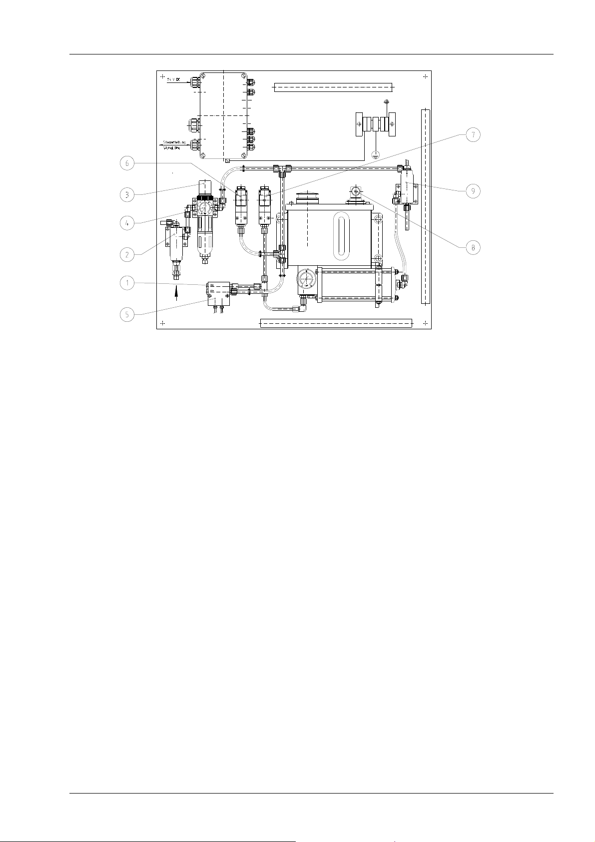
Lubrication instruction 3.2/1-2
3. First commissioning
1. Control correct laying of feed lines and return lines.
2. Connect compressed air at the valve (2).
3. Adjust air pressure at the control valve (4) to 4.5...5 bar.
4. Fill tank with oil up to “MAX”.
5. Remove greasing lines at the bearing blocks.
6. Control pause time adjustment.
7. Release lubrication (centrifuge must not yet start).
8. Vent the dosing unit:
- Open upper screw (1), actuate pressure switch (9) shortly one time and collect
leaking oil, turn in screw (1).
- Loosen threaded pin (hexagon socket 2mm) at the bottom of the dosing unit (5)
for one turn, actuate pressure switch (9) approx.15 seconds and collect leaking
oil, turn in threaded pin. The threaded pin is located in the center of the screw,
which is marked with figure 10.
Repeat this procedure for each lubricating line.
9. Activate pressure switch (9) several times by hand until oil emerges at the end of
the greasing lines (control with palm, palm must feel oily).
10. Connect lubricating lines at the bearing blocks.
11. Activate pressure switch (9) several times by hand, until oil appears in the return
lines. Control if the air from the collecting tank can exhaust unhindered. (Not
applicable with decanter type Z 73)
12. Functional control at the pressure switch (6+7): reduce air pressure at the control
valve below 4 bar until the fault signal for "air pressure missing" and "oil pressure
missing" appears at the switch board; Adjust air pressure according to step 3.
13. Functional control oil level switch (8): Loosen fixing screws; Pull out level switch until
fault signal appears at the switch board; Install level switch again.
14. When the centrifuge is stopped, pay attention that the lubrication aggregate remains
switched on until the rotor is at standstill!
Uk3_2_1-3x8_Oel_Luft_Ex_1_221208_Pre
Flottweg
Lubrication instruction 3.2/1-3
4. Lubricant
Type: see lubricating diagram, page 3.1
Quantity: 1,75 liter (first filling 2,7 liter)
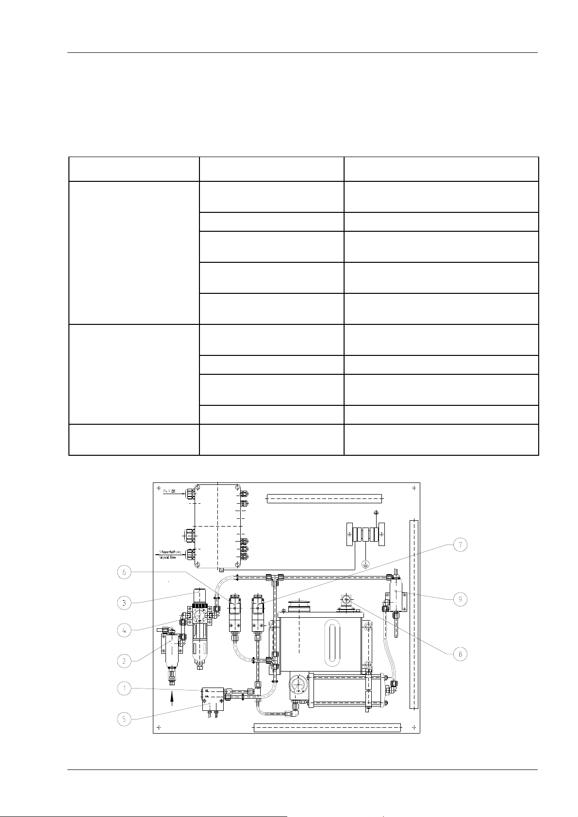
5. Faults
Problem Cause Action
Pressure switch air (6)
activated
Air pressure supply
disturbed
Restore air pressure supply
"air pressure missing" Filter contaminated Replace filter
Pressure reducer (3)
Check adjustment
misadjusted
Pressure switch (6)
Check adjustment
misadjusted
Solenoid valve (2) closed Check solenoid valve
Release solenoid valve
Pressure switch air (7)
Air pressure too low Check air pressure supply
activated
"oil pressure missing" Lack of oil Refill oil
Manual operation at
Release interlock
valve (9) arrested
Piston pump defective Renew piston pump
Float switch (8)
Oil level below “MIN” Refill oil
activated
Uk3_2_1-3x8_Oel_Luft_Ex_1_221208_Pre
Flottweg
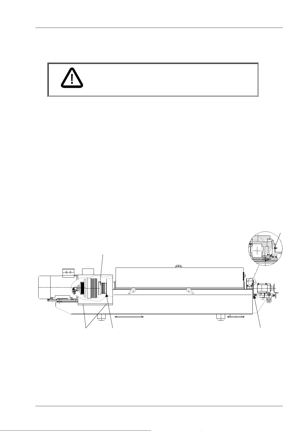
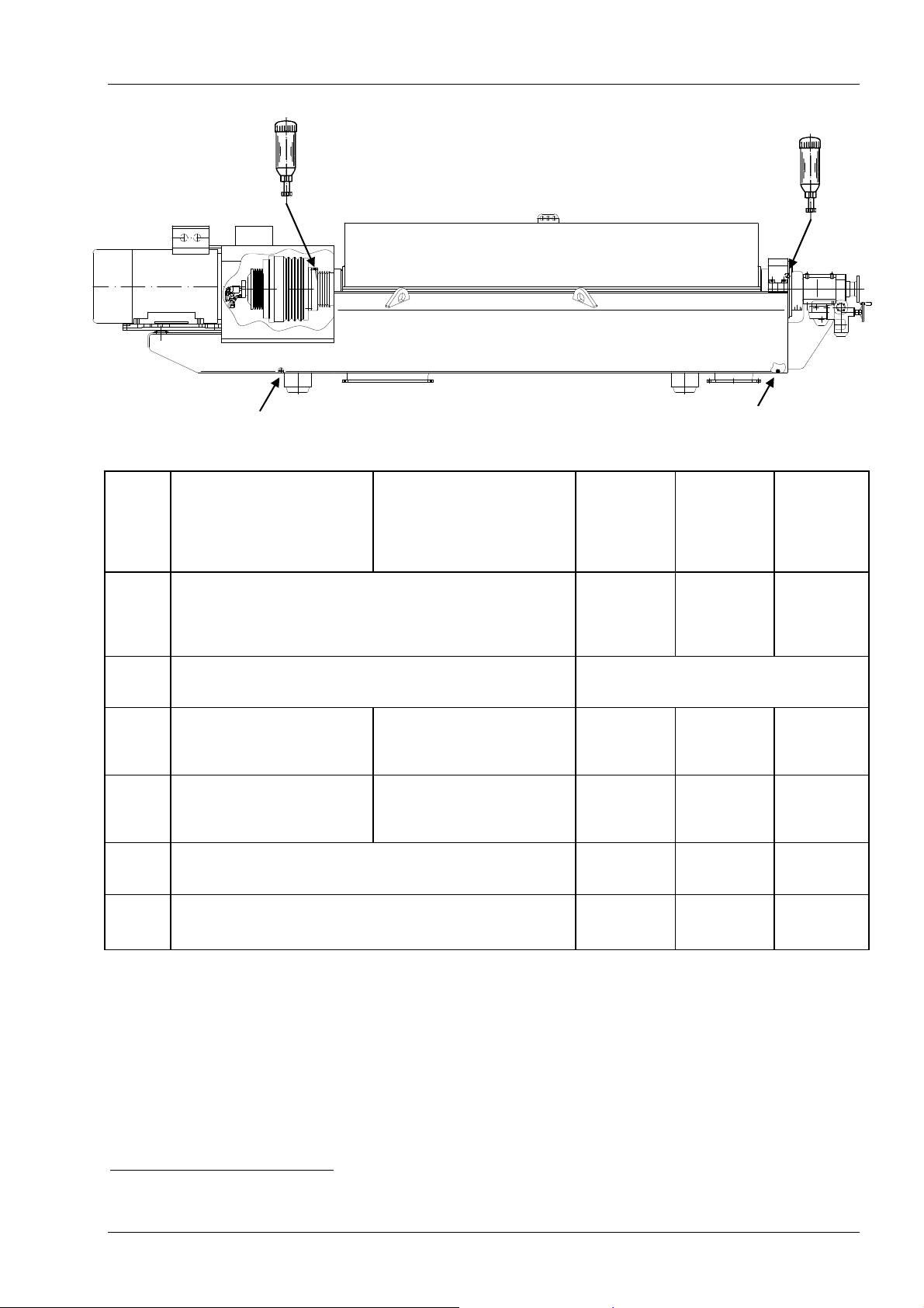
Lubrication instruction 3.2/2
WARNING
Lubrication instructions for scroll bearing
1. Relubrication of the scroll non-locating bearing (drive side)
The grease nipple for the scroll non-locating bearing is located at the drive flange.
Remove screws (1), open belt guard.
Rotate rotor by hand until you can reach the grease nipple (2).
Greasing intervals and -quantity see sheet 3.1.
Remove used grease at the discharge (4).
Relubrication of the scroll thrust bearing (feed side)
2.
The grease nipple for the scroll thrust bearing is located at the bearing block at the
feed side.
Unscrew two hexagon socket screws and remove cover (3).
Rotate rotor by hand until you can reach the grease nipple through the bore.
Greasing intervals and -quantity see sheet 3.1.
Close belt guard and tighten screws (1).
Remove used grease at the discharge (5).
Grease nipples rotate with high speed!
DANGER OF INJURY!
Lubricate only when rotor is at standstill.
1
2
4
3
5
Uk3_2_2_Z8E_080114-Pre
Flottweg
 Loading...