

Flotronic F Slim series, F 500 series, F 710 series, F K series Installation, Operation And Maintenance Manual
Page 1
The simplest ideas are often the best
Flotronic ‘One - Nut’ pumps
Installation Operation and
Maintenance Manual
Flotronic One-Nut Air Driven Double Diaphragm Pumps
and Ancillary Equipment
PLEASE KEEP FOR
FUTURE REFERENCE
ATEX APPROVED PUMPS
ATEX Gas
Group
IIC
compliant
pumps now
available
Page 2
The Pumps
F Series award-winning metal pumps
Machined from solid material, these compact and self-draining
pumps are available in 316 stainless steel, aluminium and also
exotic metals, including Hastelloy®. These pumps can be used in
a wide range of industries including chemical, cosmetic, paints,
pharmaceutical, adhesive and hygienic applications. Recently voted
winner of the prestigious Food Hygiene Award for Food Processing
and Manufacture.
Only ‘one nut’ to access diaphragms with pump ‘in-line’
Only four nuts and bolts to access balls and seats (where fitted)
Only four bolts to maintain air valve with pump ‘in-line’
†Max operating temp 121oC (250oF) with high temp diaphragm
(specify H as 6th digit in pump code)
F Series Polypropylene, PVC, PVDF and aluminium pumps
Solid blocks of plastic supported by metal air domes, top and
bottom plates and through studs offer safety without compromising
fast maintenance. Normally used for solvents/chemicals and dyes
and often as a less expensive option for stainless steel.
Only ‘one nut’ to access diaphragms with pump ‘in-line’
Only four nuts to access balls and seats
Only four bolts to maintain air valve with pump ‘in-line’
†Max operating temp 80oC for all plastic pumps.
121oC for aluminium with high temp diaphragms.
F Series stainless steel and exotic metal pumps
Fabricated 316 or 304 stainless steel or Hastelloy®on all wetted
metal parts offers unrivalled versatility. These pumps are used
extensively throughout industry from acids to adhesives, cosmetics
to ceramics, petrochemicals to paper stock and solvents to solids
in suspension. Even dairy and food stuffs.
Only ‘one nut’ to access diaphragms with pump ‘in-line’
Only two nuts and bolts to access balls and seats
Only four bolts to maintain air valve with pump ‘in-line’
†Max operating temp 121oC (250oF) with high temp diaphragm
(specify H as 6th digit in pump code)
F Series Chemflo virgin and anti-static PTFE pumps
A solid block of virgin or anti-static PTFE housed completely inside
an outer metal ‘Pressure Vessel’ of carbon or stainless steel gives
inherent safety whilst retaining ‘one nut’ maintenance. Used for
extremely hazardous acids and chemicals where only PTFE can
be used and often in pilot plants or as emergency pumps where
chemicals are unknown.
The ultimate solid PTFE Double Diaphragm Pump
†Max operating temp 121oC (250oF) with high temp diaphragm
(specify H as 6th digit in pump code)
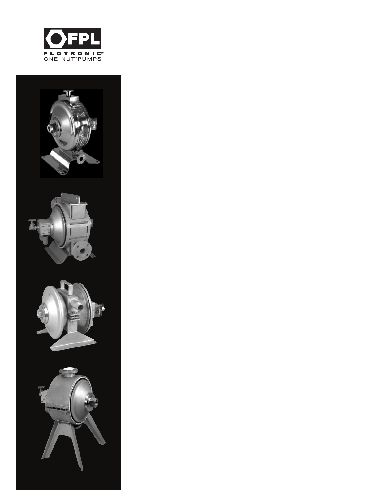
SLIM
500
710
K
Page 3

Section No. Description Page
Section 1 General Information 2
Section 2 Training 2
Section 3 Limitation of Use 3
Section 4 Essential Safety Requirements (ESR) 4
Section 5 ATEX Safety Manual 6
Section 6 Installation 8
Section 7 Hydrostatic Testing 10
Section 8 Operation of Pumps & Torque Figures 11
Section 9 Noise Levels 13
Section 10 Servicing & Diaphragm Fitting Instructions 14
Section 11 F Series 500 Style Plastic & Aluminium Pumps 18
Section 12 F Series 710 Style Stainless Steel Pumps 24
Section 13 F Series Good Food Style Pump 30
Section 14 F Series Slim Style Metallic Pumps 35
Section 15 F Series ‘K’ Style Chemflo All PTFE 40
Section 16 Air Valves 45
Section 17 Pulsation Dampers 47
Section 18 Rupture Protection, Barrier & Alarm Systems 52
Section 19 Count & Stop Pumps All Series 60
Section 20 Trouble Shooting 62
Section 21 Further Assistance 64 & 67
Contents
1
Page 4

Section 1 - General Information
“Declaration of Conformity”
“As defined by the Machinery Directive 2006/42/EC, and complies with the essential Health & Safety
requirements, Annex 1, and the technical construction file requirements of the Directive.
This pump complies with the Pressure Equipment Directive (PED) 97/23/EC Category 1 Module A.”
A declaration of conformity accompanies all pumps, and all pumps carry the C.E. Mark as required by U.K
and European Law effective January 1st 1995.
Section 2 - Training
It is recommended, and a part of the CE regulations that users personnel who will be involved in the
installation, operation and/or maintenance of FPL products should have the opportunity of an initial
training period,which can be carried out either at FPL works or customers premises by arrangement.
This training is offered by Flotronic in 3 different forms.
a Informal training in your maintenance workshop by our Technical Sales Representative on a Free of
Charge basis.
b Formal training in your training rooms by our skilled training personnel using visual aids, ‘hands on’
equipment etc, at an agreed cost to be confirmed.
c Formal training at FPL Premises by our skilled training personnel using visual aids, ‘hands on’
equipment, etc, at an agreed cost to be confirmed.
It is your responsibility to request your preferred training method now. Flotronic will not consider
responsibility for ongoing breakdowns etc, if training has not been given.
FPL offer a friendly after sales policy but, reserve the right to charge for “call out” visits that are
found to be caused through operator/fitter error.
2
General Information/Training
Page 5

Section 3 - Limitations of Use
FPL products are designed to provide performance generally, as shown in accompanying literature
associated with the individual models or series. See Section 11 to 15. All performance figures are given
in good faith and are based on tests at FPL works using water at ambient temperature.
Operating temperatures are governed by the materials of construction of software parts, i.e. diaphragms,
balls, seals etc, and it is the installers responsibility to ensure that these maximum temperatures are
not exceeded under any circumstances.
Performance figures provided by FPL against individual enquiries are estimates only, and are subject
to variations depending upon air pressure and volumes of air provided by client, and to head losses due
to pipework, valves, etc which may be unknown to Flotronic estimators.
All performance figures, temperatures, flow rates, dimensions & other details are subject to change
without notice.
Due to the wide variety of products handled by FPL pumps, it is impossible for FPL to give a firm
recommendation regarding materials of construction for pump components. It is the users or specifiers
responsibility to determine the effect of corrosion & abrasion, and the general suitability of any pump
supplied for any individual application. FPL will, however, give advice in such material selection as it
may be able to do so in good faith.
3
Limitations of Use
Page 6

Section 4 - Essential Safety Requirements (ESR)
ATEX DIRECTIVE 2014/34/EU (EXPLOSION HAZARD SAFETY)
All FPL products that are certified to comply with the Directive also carry a specific ATEX Safety Manual
(Section 5) which must be referred to in conjunction with this manual. It is the responsibility of the user to
ensure that the equipment is correctly rated for the environment in which it is to be used.
When handling FPL products,please note weights given on FPL literature. Lifting equipment may be
required in certain cases.
Note that all pumps despatched from our works are tested with water and during storage,
packing and installation, some water will have remained in the pump body. This water may cause
spillage during handling. Water could react with the products you wish to pump,and it is your
responsibility to check this before putting the pump into operation. Water may also freeze if the pump
is exposed to sub zero temperatures. Do not operate the pump under these conditions as ice inside
the pump may cause damage to working parts of the pump.
At all times the installer must wear suitable clothing, footwear, goggles, etc for personal protection.
This particularly applies when the pump is being operated or maintained.
As with all double diaphragm pumps, it must be expected that diaphragm failure will occur without
warning and under these conditions, leakage of product can occur from the exhaust silencers unless a
guardian or barrier system is fitted (see Section 18).
If the product being processed is hazardous,then provision must be made by the user to deal with
this problem. This can be achieved by either specifying a guardian or barrier system as part of the
original pump specification or, as a retrofit from FPL works, or the silencers must be removed and
replaced by pipework which can carry the leakage to a safe place. Please note that wherever the
product is piped, pulses of mixed air and product will occur at the end of the pipework when diaphragm
failure has occurred. Provision must be made to accept the volumes of air/product mixture and the
pressures realised at that point.
If the product being pumped is corrosive or hazardous in any form, then provision must be made in the
piping construction to accept the mixed air/product that will be discharged under diaphragm failure
conditions.
Note the product may remain inside the pump after use and may be under pressure.
4
Essential Safety
Requirements (ESR)
Page 7

Health Hazard Warning
Please note that PTFE is used in FPL pumps when specified in diaphragms, seals, seats and other
components.
At temperatures up to 250°C polytetrafluoroethylene (PTFE) is completely inert so that on the rare
occasions when the diaphragm fails or cracks,there is no direct danger from these components, other
than if particles are allowed to be carried into the process liquids.
At higher temperatures however, small quantities of toxic fumes can be produced and the direct inhalation
of these can cause an influenza type of illness, which may not appear for some hours, but which subsides
without after effects in 24 to 48 hours. Such fumes can arise from PTFE particles picked up on the end
of a cigarette, or in the presence of any open flame or similar ie: electric fire, therefore smoking should
be prohibited when pumps are being serviced or PTFE components are being handled.
The disposal of PTFE components such as diaphragms etc. must be carefully controlled and under no
circumstances should be burned. When these components are scrapped, disposal must be made safely
and if disposed of through normal rubbish collection, the local authorities should be advised that such
disposal is being carried out.
5
Health Hazard Warning
Page 8
Section 5 - ATEX Safety Manual
For Air Driven Diaphragm Pumps
and Ancillary Equipment
User Instructions to ensure compliance with
European Directive 2014/34/EU
1.0 GENERAL 6-1
1.1 ATEX Directive 2014/34/EU 6-1
1.2 Disclaimer 6-1
1.3 Personnel qualifications and training 6-1
2.0 SAFETY 6-2
2.1 Summary of safety marking 6-2
2.2 Products used in potentially explosive atmospheres 6-2
2.3 Scope of compliance 6-2
2.4 Marking 6-3
2.5 Avoiding excessive surface temperatures 6-3
2.6 Preventing the build up of explosive mixtures 6-4
2.7 Preventing sparks 6-4
2.8 Preventing leakage 6-5
2.9 Maintenance to the diaphragm pump to avoid the hazard 6-5
2.10 Additional Safety Instructions 6-6
6
ATEX Safety Manual
Page 9

1.0 GENERAL
These instructions must always be kept close to the product’s operating location or directly with the
product.
These instructions are intended to facilitate familiarisation with the product and its permitted use to
help satisfy ATEX safety requirements. The instructions may not have taken into account local
regulations; ensure such regulations are observed by all, including those installing the product.
Always co-ordinate repair activity with operations personnel, and follow all plant safety requirements and
applicable safety and health/law regulations.
These instructions should be read prior to installing, operating, using and maintaining the equipment
in any region worldwide and in conjunction with the main user instructions provided. The equipment must
not be put into service until all the conditions relating to safety instructions have been met.
1.1 DIRECTIVE 2014/34/EU
It is a legal requirement that machinery and equipment put into service within certain regions of the
world shall conform with the applicable CE Marking Directives for Equipment for Potentially Explosive
Atmospheres (ATEX).
Where applicable the Directive covers important safety aspects relating to the equipment, its use
and the satisfactory provision of technical documents. Where applicable this document incorporates
information relevant to these Directives. To establish if the product itself is CE marked for a Potentially
Explosive Atmosphere check the nameplate and the Certification provided.
1.2 Disclaimer
Information in these User Instructions is believed to be reliable. In spite of all the efforts of Flotronic
Pumps Ltd to provide sound and all necessary information, the content of this Manual may appear
insufficient and is not guaranteed by Flotronic Pumps Ltd as to its completeness or accuracy.
1.3 Personnel qualifications and training
All personnel involved in the operation, installation, inspection and maintenance of the unit must be
qualified to carry out the work involved. If the personnel in question do not already possess the necessary
knowledge and skill, appropriate training and instruction must be provided. If required the operator may
commission the manufacturer/supplier to provide applicable training.
6-1
ATEX Safety Manual
Page 10

2.0 SAFETY
2.1 Summary of safety marking
These instructions contain the following specific ATEX safety marking where non-observance of the
instruction will cause a hazard.
This symbol indicates explosive atmosphere marking according to ATEX. It is used in safety
instructions where non-compliance in the hazardous area would cause the risk of an explosion.
2.2 Products used in potentially explosive atmospheres
Measures are required to:
Avoid excess temperature
Prevent build up of explosive mixtures
Prevent the generation of sparks
Prevent leakages
Maintain the pump to avoid hazard
The following instructions for pumps and pump units when installed in potentially explosive atmospheres
must be followed to help ensure explosion protection. Both electrical and non-electrical equipment must
meet the requirements of European Directive 2014/34/EU.
2.3 Scope of compliance
Use equipment only in the zone for which it is appropriate. Always check that pumps and ancillary
equipment are suitably rated and/or certified for the classification of the specific atmosphere in
which they are to be installed.
Where Flotronic Pumps Ltd has supplied only the bare pump, the Ex rating applies only to the pump.
The party responsible for installing the pump shall select any additional equipment, with the necessary
CE Certificate/Declaration of Conformity establishing it is suitable for the area in which it is to be installed.
6-2
ATEX Safety Manual
Page 11
2.4 Marking
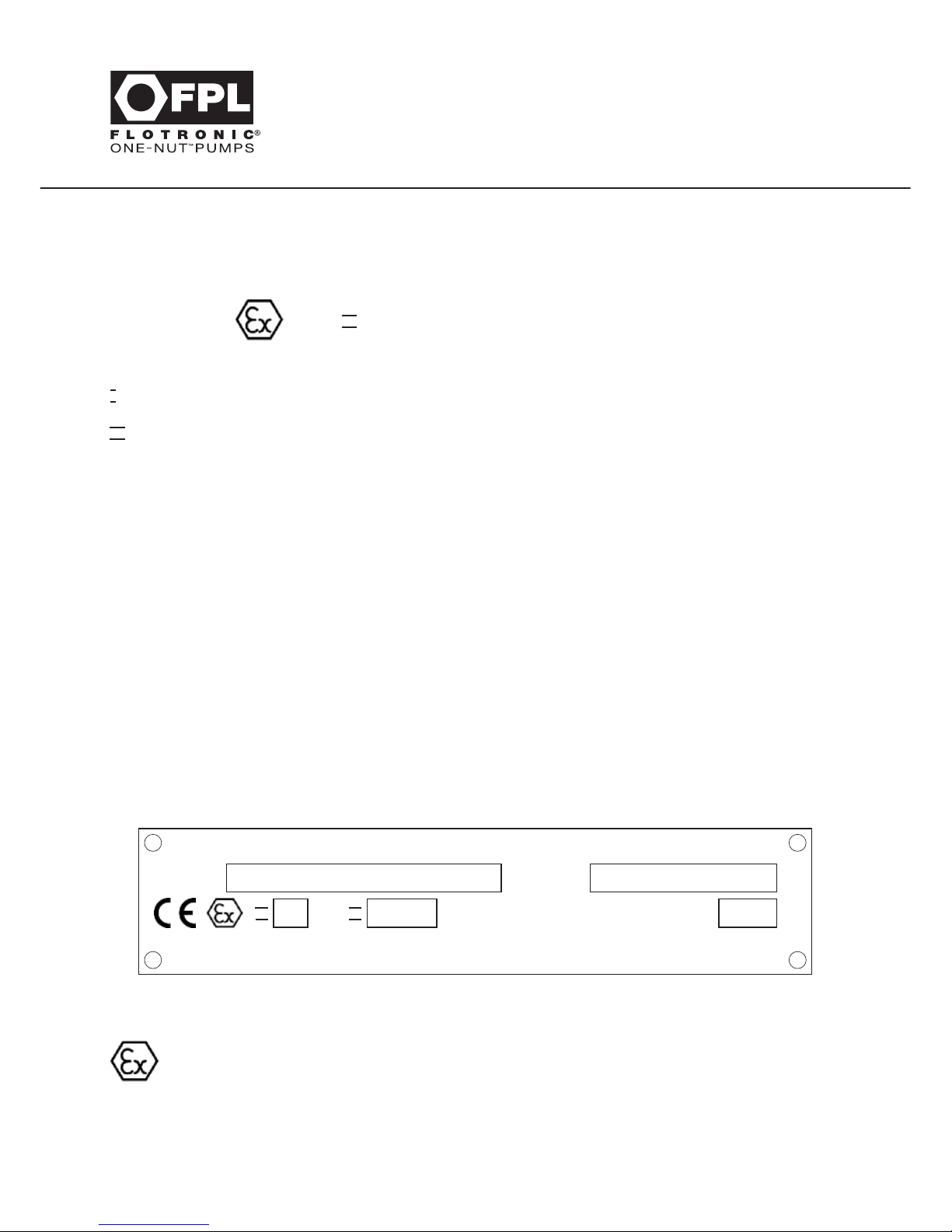
An example of ATEX equipment marking is shown below. The actual classification of the pump will be
engraved on the nameplate.
Equipment Group
I = Mining
I I = Non-mining
Category
2 or M2 = High level protection
3 = normal level of protection
Gas and/or Dust
G = Gas; D = Dust
= Atmosphere group
Maximum surface temperature (Temperature Class) (see Section 2.5)
Special attention must be paid to the marking on the ATEX nameplate as the use of ‘pirate’ spare parts
will invalidate the ATEX certification.
It is essential to heed the instruction prohibiting dismantling of the equipment in a flammable atmosphere
where applicable.
Example ATEX Nameplate
2.5 Avoiding excessive surface temperatures
ENSURE THE EQUIPMENT TEMPERATURE CLASS IS SUITABLE FOR THE HAZARD ZONE
2.5.1 Pump liquid temperature
Pumps have a temperature class as stated in the ATEX Ex rating on the nameplate. These are based on a
maximum ambient of 40
o
C (104oF); refer to Flotronic Pumps for higher ambient temperatures.
6-3
ATEX Safety Manual
FLOTRONIC PUMPS LTD Bolney, West Sussex RH17 5NA
EQUIPMENT MUST BE EARTHED AND ONLY GENUINE FPL SPARES USED
DO NOT DISMANTLE IN FLAMMABLE ATMOSPHERE
TYPE S/No.
MAX. PRESS. 7 BARG MAX. TEMP.
o
CI I I I
I I
2 G/D 135oC (T4)
S Q 5 6 6 T T 6 S B S P B E P
2 B T 4
S 1 1 1 / 0 3 / 0 6
1 0 0
Page 12

The surface temperature of the pump may be influenced by the temperature of the liquid handled.
The maximum, permissible liquid temperature depends on the temperature class and must not exceed
the values in the table applicable below. The temperature rise at the seals, bearings and due to the
minimum permitted flow rate is taken into account in the temperatures.
Maximum permitted liquid temperature for diaphragm pumps:
Temperature Maximum Temperature limit of liquid handled
Class to surface temperature depending on material and construction variant.
EN 13463–1 permitted Consult Flotronic Pumps Ltd.
T6 85
o
C (185oF) Consult Flotronic Pumps Ltd
T5 100
o
C (212oF) Consult Flotronic Pumps Ltd
T4 135oC (275oF) 105oC (221oF)
T3 200oC (392oF) 115oC (239oF)
T2 300oC (572oF) 115oC (239oF)
T1 450oC (842oF) 115oC (239oF)
Where there is any risk of the pump being run for prolonged periods against a closed or partially closed
valve generating high liquid and casing external surface temperatures, it recommended that users fit
an external surface temperature protection device.
2.5.2 Additional requirements for self-priming conditions
Where the system operation does not ensure control of priming, and the maximum permitted surface
temperature of the T Class could be exceeded, it is recommended for users to fit an external surface
temperature protection device.
2.6 Preventing the build up of explosive mixtures
ENSURE PUMP IS PROPERLY FILLED WHENEVER POSSIBLE AND DOES NOT RUN DRY
FOR LONGER THAN 5 MINUTES CONTINUOUSLY
Ensure the pump and relevant suction and discharge pipeline system is totally filled with liquid during
the pumping operation, so that an explosive atmosphere is prevented.
If the operation of the system cannot avoid this condition, ensure that the pump does not run dry for
more than 5 minutes continuously.
To avoid potential hazards from fugitive emissions of vapour or gas to atmosphere the surrounding
area must be well ventilated.
2.7 Preventing sparks
To avoid the potential hazard from random induced current generating a spark, the earth stud
on the pump casing or foot must be connected.
6-4
ATEX Safety Manual
Page 13

Avoid electrostatic charge: Do not rub non-metallic surfaces with a dry cloth for cleaning etc; ensure the
cloth is damp.
2.8 Preventing leakage
The pump must only be used to handle liquids for which it has been approved to have the correct
corrosion resistance.
Avoid entrapment of liquid in the pump and associated piping due to closing of suction and discharge
valves, which could cause dangerous excessive pressures to occur if there is heat input to the liquid.
This can occur particularly if the pump is stationary.
Bursting of liquid containing parts due to freezing, must be avoided by draining or protecting the pump
and ancillary systems.
If leakage of liquid to atmosphere can result in a hazard, the installation of a liquid detection device is
recommended.
2.9 Maintenance to the double diaphragm pump to avoid the hazard
CORRECT MAINTENANCE IS REQUIRED TO AVOID POTENTIAL HAZARDS WHICH GIVE A
RISK OF EXPLOSION
The responsibility for compliance with maintenance instructions is with the plant operator.
To avoid potential explosive hazards during maintenance, the tools, cleaning and painting materials used
must not give rise to sparking or adversely affect the ambient conditions. Where there is a risk from such
tools or materials, maintenance must be conducted in a safe area.
It is recommended that a maintenance plan and schedule is adopted, in line with the user instructions
provided, to include the following:-
a Any auxiliary systems installed must be monitored, if necessary, to ensure they function correctly.
Particular care must be paid to checking the Sentinel diaphragm protection system vacuum on a
daily basis.
b Check for any leaks from gaskets and seals. The condition of the divider seal must be checked
regularly to ensure correct functioning.
c Check that the duty condition is in the safe operating range for the pump.
d Check that dirt and dust is removed from operational areas of the pump.
e Check the free operation of the air valve spool.
f Renew the thrust tube bearings every 1000 running hours.
g Inspect the diaphragms at least every 1000 running hours and renew if any sign of damage is apparent.
6-5
ATEX Safety Manual
Page 14

2.10 Additional Safety Instructions
a Pumps and ancillary equipment must be drained, cleaned and decontaminated prior to any change
of duty.
b Where pumps and ancillary equipment contain non-conductive plastic wetted components,
dismantling for maintenance must take place in a safe area away from the flammable hazard, or
the equipment made safe by purging with nitrogen.
c When installing a pump either for the first time or after maintenance, a check must be made to
ensure that the earth connection terminal on the pump and any external metalwork is at
ground potential.
d Ensure that all metallic pump shrouds and casings are correctly fitted after maintenance, and that earth
continuity between them is at ground potential.
e Where a counter or count and stop device is fitted, it is for indicating the number of cycles run only,
and not to use as a means of process flow control or for performing a safety function.
f Where an air regulator or filter regulator is fitted, the locking facility where applicable should be used
to ensure the maximum working pressure of 7.2 bar is not exceeded.
g Ensure the maximum permissible nozzle bending moment of 30 Nm is not exceeded.
6-6
ATEX Safety Manual
Page 15
7
Your Notes
Page 16

Section 6 - Installation
All FPL pumps are provided with mounting plates and suitable holes for bolting the pump to base
plates or foundations. Pumps must be mounted and used with suction and delivery connections as shown
in the literature and our arrangement drawings, unless otherwise agreed with FPL.
Portable pumps should be used with the pump located on a flat surface, with suction and delivery
connections as shown in FPL literature. Any associated pipe-work either flexible or rigid, should not
be fitted in such a way that the pump is subjected to movement caused by vibration, or pipe stresses
that may cause the pump to move in such a manner that it could create a hazard to personnel.
Flexible or fixed pipe-work may be connected to the wet side inlet and outlet of the pump, but allowance
should be made for pipe supports where necessary. With solid pipe-work, a short section of flexible
hose is advisable to absorb any vibration that may occur when the pump is running. It is emphasised
that to obtain the best performance from the pump, pipe-work should be of a bore of not less than that
of the pump connection, and with the minimum number of bends and restrictions.
All pipes and pipe connections to the pump must be attached to the appropriate standards. Connections
to the pump may be flanged, screwed, or with special clamp arrangements, dependent upon clients
requests. Bolting and joint materials must be to appropriate standards and be suitable for handling the
product to be pumped. The pump must not be subjected to stresses induced by pipe-work.
Air pipe-work and connections must be suitable for the pressures to be used, and must be adequate
for the purpose. Maximum air pressure must not exceed 7.2 bar (105 p.s.i) and the pump should be
operated at the lowest pressure that will give adequate performance from the pump without stalling.
Air supply pipe-work and fittings must not be less than
3
/8” diameter for pumps with 7” and 10”
diameter diaphragms and3/4” or 1" diameter for pumps with 12” and 14” diameter diaphragms.
Pumps with 7” and 10” diameter diaphragms fitted with guardian or sentinel arrangements must have
air supply pipe-work of not less than
1
/2” diameter.
Air connections to all pumps must include a short length of flexible pipe-work to avoid side or end
loads being applied to the tie rod assembly. Such loads will be transmitted to the centre divider seal
and may promote excessive wear and/or shorter diaphragm life.
A clean supply of compressed air is required. The air valve will run best on dry or non-lubricated air.
Air should be available in sufficient quantity and pressure to operate the pump.
If remote operation of the pump is to be used, an additional isolating valve must be provided adjacent
to the pump, which can be turned off when the pump is not in use, or when the pump is being serviced.
Remote air on/off valves, if fitted in the air system, must not be located more than 5ft(1.5m)
from the pump to avoid the pump getting into a stall situation, caused by the reservoir effect of
extended lengths of large bore pipe-work.
Flotronic Pump connections are designed of adequate thickness to absorb normal pipe loads/
connections. Do not over tighten or force pipes into threads (particularly female plastic threads).
8
Installation
Page 17
9
Installation
Delivery
Suction
Diaphragm
Diameter
Stainless steel range
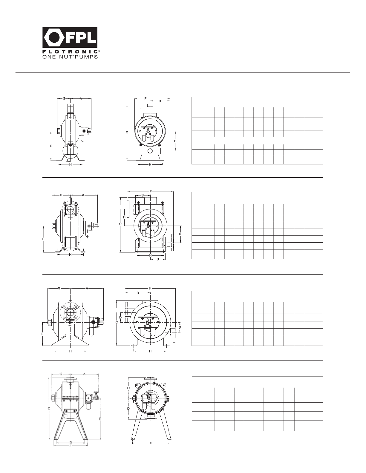
Size ABCDE FGHWt/kg
1
⁄2” - 1” 159 117 332 109 175 215 92 160 17 7”
1
⁄2” - 1” 172 129 425 145 217 255 109 203 25 10”
11⁄2”-2” 207 163 466 163 242 290 109 203 28 10”
11⁄2”-2”- 3” 305 180 600 190 300 350 187 250 75 12”
Aluminium range
1
⁄2”-1” 159 89 312 109 175 187 92 160 13 7”
1
⁄2”-1”
-11⁄2”-2” 172*35 437 171 256 254 109 203 22 10”
1
1
⁄2”-2”-3” 305 125 520 190 300 295 187 250 50 12”
Delivery
Suction
Diaphragm
Diameter
Polypropylene, PVC, PVDF & Aluminium
Size ABCDE FGHWt/kg
1
⁄2” - 1”* 183 87 323 110 178 225 116 130 13 7”
1
⁄2” 190 114 360 115 170 355 145 203 17 10”
1” 200 114 390 121 186 355 145 203 18 10”
11⁄2” 230 114 419 129 200 355 145 203 19 10”
2” 230 163 450 132 215 355 145 203 20 10”
11⁄2”-2”-3”* 323 150 522 189 295 323 210 220 50 12”
2” - 3” 350 190 530 148 270 550 235 330 75 14”
Suction
Delivery
Diaphragm
Diameter
Stainless Steel & Exotic Metals
Size ABCDE FGHWt/kg
1
⁄2” 190 156 282 60 146 311 145 203 18 10”
1” 200 156 282 60 146 311 145 203 18 10”
11⁄2” 230 156 282 60 146 311 145 203 19 10”
2” 230 156 282 60 146 311 145 203 20 10”
2”
- 3” 350 250 460 108 230 500 235 254 80 14”
Delivery
Suction
Maximum operating pressure 7.2 bar (105 PSIG) Dimensions in mm
Diaphragm
Diameter
Chemflo Virgin & Anti-Static PTFE
Size ABCDE FGHWt/kg
1” 240 235 550 180 370 300 140 325 42 10”
11⁄2” 240 235 550 180 370 300 140 325 45 10”
2” 240 250 570 180 390 315 140 345 48 10”
2”
- 3” 350 350 780 260 520 420 235 470 95 14”
Maximum operating pressure 7.2 bar (105 PSIG) Dimensions in mm
Maximum operating pressure 7.2 bar (105 PSIG) Dimensions in mm
Maximum operating pressure 7.2 bar (105 PSIG) Dimensions in mm
SLIM
500
710
K
Page 18

10
Section 7 - Hydrostatic Testing
All double diaphragm pumps can suffer damage to diaphragms, which will result in shorter life if
pressure is applied on the wet side of the pump without adequate support on the air side. If an FPL pump
is installed into a piping system which is to be hydrostatically tested using pressures in excess of 2 bar
(30 psi) and not exceeding 10.5 bar, the following procedure should be adopted.
1. looking at the air valve into the pump, remove left-hand air silencer and connect water supply.
2. push right-hand white button on air valve in as far as it will go.
3. turn on water supply at the same time as water is being applied to the piping system.
4. apply hydraulic pressure to both piping system and the air silencer inlet at the same time,
and at the same pressure.
DO NOT EXCEED 10.5 BAR ON ANY PART OF THE PUMP SYSTEM.
5. allow pressure to be reduced to atmospheric pressure on both piping and air systems at the
same time.
6. when subsequently operating the pump with an air supply connected, open the air supply
valves slowly and allow water to be fully exhausted from the air system. Note that water
remaining in the air side of the pump will be ejected via the exhaust silencers, water in the
product side of the pump will pass into the downstream pipework.
PUMPS/DAMPERS WITH JACKETED BODY/MANIFOLDS
The jacketing of all Flotronic Pumps/Dampers supplied before 31/12/98 has a maximum working
pressure of 2 Bar G. Under no circumstances must super heated steam be used in these jackets.
After 1/1/99 the jackets of pumps/dampers are tested to 7.2 bar separately and independently of the
pump Certificate of Conformity/Test Certificate.
Hydrostatic Testing
Page 19

11
Section 8 - Operation of Pumps & Torque Figures
For pump performance curves refer to the Flotronic general product brochure or company website
www.flotronicpumps.co.uk. Before the pump is put into service and after any maintenance, tighten the
fastenings to the torque figures given below; ensuring fasteners are suitably lubricated.
These figures are for guidance only. Under extreme conditions of pressure, temperature etc it may be
necessary to adjust individual values. In this event, please contact FPL for advice.
TIGHTENING TORQUES -
IMPORTANT
Operation of Pumps
& Torque Figures
DIAPH LB/FT NM KGM Pump Type & Material
Main Nut PTFE/Nitrile 100 135 13.5 All pumps
Manifold 7 10 1 Metal Pumps Only
Manifold 680.8 Polypropylene
Pumps with 7” Diameter Diaphragms
DIAPH LB/FT NM KGM Pump Type & Material
Main Nut PTFE/Nitrile 175 240 24 All pumps
Manifold 15 20 2 Metal Pumps Only
Manifold 7 10 1 Polypropylene
Body Clamp 26 35 3.5 K Series Chemflo
Pumps with 10” Diameter Diaphragms
DIAPH LB/FT NM KGM Pump Type & Material
Main Nut PTFE/Nitrile 325 440 44 All pumps
Manifold 15 20 2 Metal Pumps Only
Manifold 11 15 1.5 Polypropylene
Pumps with 12” Diameter Diaphragms
DIAPH LB/FT NM KGM Pump Type & Material
Main Nut PTFE 450/500 610/680 61/68 All pumps
Nitrile 375 510 51 All pumps
Manifold 37 50 5 Stainless Steel 710 Style
Manifold 15 20 2 Plastic/Aluminium
Body Clamp 26 35 3.5 K Series Chemflo
Pumps with 14” Diameter Diaphragms
Page 20

12
The pump may be started by applying air pressure to the air valve fitted. In the event of failure to start
the manual overrides fitted to the air valve below the air inlet should be pushed so that the spool is
repositioned, repeat as necessary.
Note the pump will not operate if the head of fluid resistance on the fluid delivery side of the pumping
is equal to, or exceeds air pressure. If a valve is fitted to the suction or delivery side of the pump, this
must be in the open position.
If a valve is fitted adjacent to the pump on the delivery side of the fluid pipe-work, this may be used to
control flow and when necessary, closed to stop flow without damage to the pump. Alternatively, the
pump may be controlled by opening or closing, or varying the air supply, using the valve fitted.
The pump is normally fitted with a 5 port air valve on pumps with 7” and 10” diameter diaphragms,
and with special design, FPL valves on larger size pumps. Capacities and flow rates shown on our
literature and data sheets are based on the use of these valves. Capacities and flow rates may vary if
other types of 5 port valves are fitted. Flotronic pumps reserve the right to supply pumps fitted with
alternative types of valve without notice.
Operation of Pumps
& Torque Figures
DIAPH LB/FT NM KGM Material
Air dome fixings PTFE/Nitrile 15 20 2 All dampers
Air valve fixings 7 10 1 All dampers
Pulsation Dampers with 10” and 14” diameter diaphragms
Operation of Pumps & Torque Figures - continued
Page 21

13
Section 9 - Noise Levels
During normal operation of the pump,the maximum noise level will generally not exceed 85 decibels at one
metre distance. The actual value achieved will be dependent on the pump model type and process
operating conditions. Refer to FPL for information where applications require a specific noise criteria.
Note:
Whilst every effort is made to reduce pump noise and protect personnel from exposure,it is necessary to
have silencers on our pumps to release used air to the environment. In certain circumstances, this air can
carry pumped liquid in it which can escape to the environment through the silencers. Flotronic, therefore,
recommend pumps are purchased with either Guardian or Sentinel systems and promote this at time
of sale. However, if your pump is unprotected with the Diaphragm Rupture Protection system you can:
1. Fit a stainless steel guard around the silencers (available on request).
2. Fit alternative metal silencers (available on request).
The standard pump silencers are made of plastic as these give superior performance characteristics to
all Flotronic pumps.
These silencers are carefully selected to ensure optimum pump performance. Do not use alternative
makes.
Noise Levels
Page 22

14
Section 10 - Servicing & Diaphragm Fitting Instructions
All “One Nut” fast maintenance FPL pumps have a common construction through the horizontal centre
line of the pump, with the single nut being a device which holds the air system, diaphragms and thrust
tube assembly together, via the tie rod. The following operations apply to all pumps except those fitted
with guardian or alarm systems, see Section 6 & Section 18.
IMPORTANT NOTICE
Air supply to the pump must be isolated before any maintenance is commenced.
Please remember that process liquid will be inside the pump body and manifolds and maybe under
pressure. It is important that maintenance personnel are wearing suitable protective clothing at all times.
When the pump is to be dismantled, access to diaphragms can be made with the pumps installed in
rigid pipe-work or can be carried out on the bench.
To obtain access to the diaphragms, it is necessary to remove the centre tie rod which carries the 5 port
air system and the air dome. This is carried out by first unscrewing the nut at the end of the tie rod and,
if necessary, restraining rotation of the air valve. The rectangle steel base to which the air valve is
attached must be used to counter the rotation of the spanner, and under no circumstances should the
5 port air valve be held in a vice or used as a means for preventing rotation.
Having released the large nut and adjacent washer or washers, the air dome at the nut end is free to
be removed, and this should be carefully done to avoid damage to the rubber ‘O’ ring seal inside the
air dome. The tie rod air block & air valve assembly can now be withdrawn from the opposite end.
The diaphragms are now exposed and, by gripping the edges of the diaphragms with fingers, (not sharp
edge tools) they can be prised away from the body of the pump to obtain a grasp on each diaphragm.
Diaphragm Fitting Instructions
(Read note re: Divider Seal top of page 17)
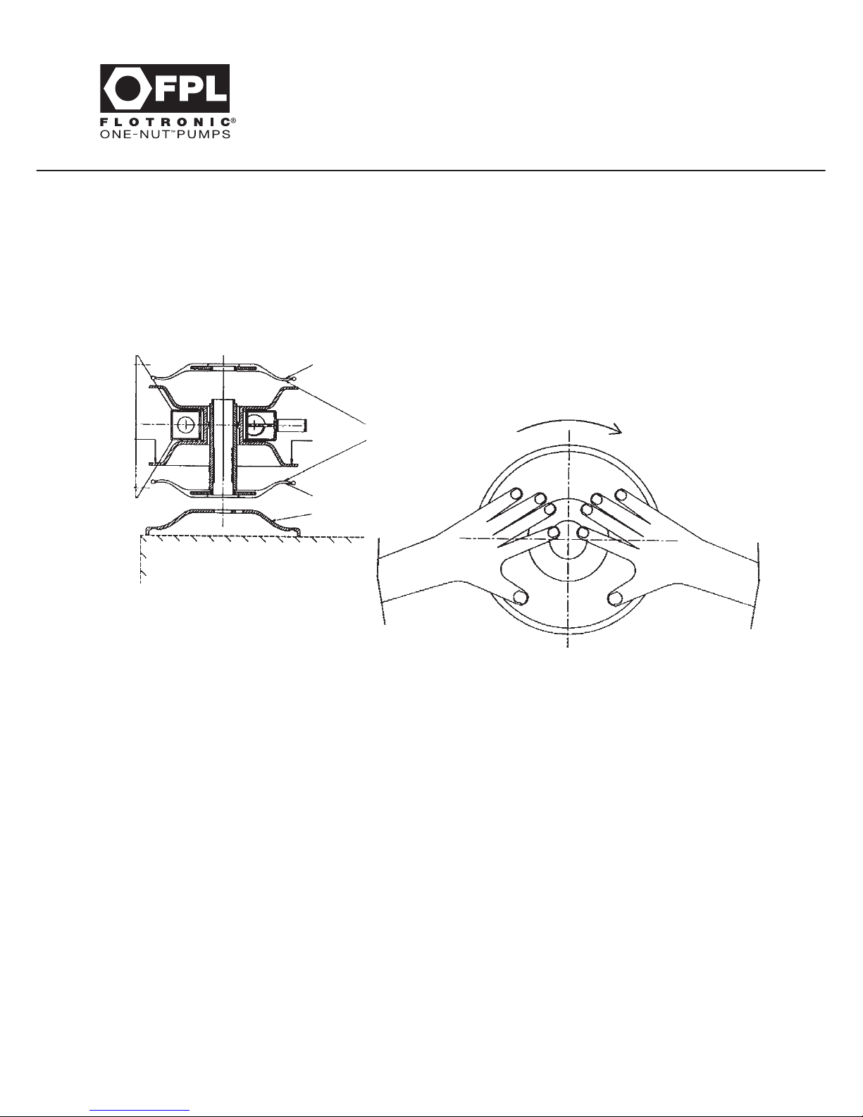
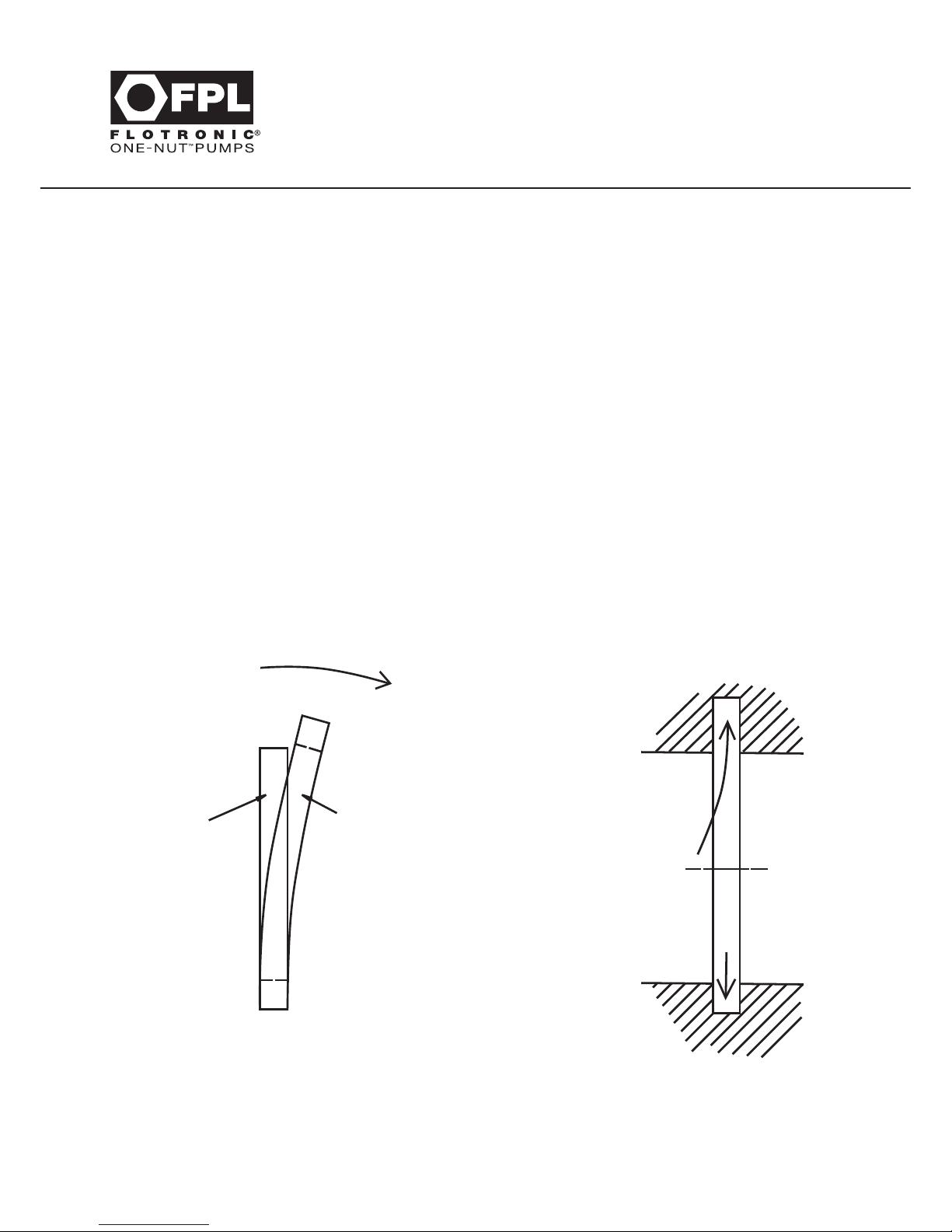
Rotate the diaphragms in an anti-clockwise direction to each other, to unscrew from the centre connecting
tube. If only one detaches from the centre tube, the tube may then be withdrawn from the pump body and
placed in a bench vice using soft jaws to aid release of the second diaphragm.
New diaphragms can be fitted using reverse procedure and in accordance with the diaphragm fitting
instructions (see sketch on next page). Always replace both diaphragms when servicing pumps.
Refitting new diaphragms should be carried out using the following procedures:
1. ensure that the centre thrust tube thread and angular seal faces are cleaned and free from dirt.
2. lightly grease thread unless used in sanitary environments.
3. screw on the first diaphragm using bench vice with soft jaws if necessary with PTFE face inwards
towards the thrust tube, as tightly as possible. Wait five minutes after initially tightening and
then retighten. If nitrile or rubber diaphragms are fitted, the concave face should be towards the
thrust tube.
Servicing & Diaphragm
Fitting Instructions
Page 23
15
4. fit thrust tube with one diaphragm attached passing tube through the centre body. When tension
divider seals are fitted,use the plastic nose cone (Supplied with pump - if in doubt contact FPL),
to aid assembly.
5. repeat 1 & 2 to screw on second diaphragm. Wait five minutes after initially tightening and then
retighten.
6. if difficulties are experienced in fitting second diaphragm:
Servicing & Diaphragm
Fitting Instructions
Diaphragm
Diaphragm
Inverted air dome
PTFE
sides
facing
Press
down
and
hold
Press
down
and
hold
The diaphragm should either be warmed in hot but not boiling water or, if possible, the body should be
turned on its side and placed on top of an air dome to aid fitting. It is not possible to over tighten these
diaphragms by hand. Sharp edge tools or pliers should never be used. Diaphragms can be sufficiently
tightened by hand in a clockwise rotation one against the other.
Note:
PTFE faced diaphragms will creep around the seal depending upon the environmental temperature when
fitting. Fit the diaphragms as above and leave for a few minutes before finally returning to clasp the outer
edges by hand, and give a final pinch to the seals.
ALWAYS FIT NEW SILENCERS WHEN REPLACING DIAPHRAGMS
Tools are available upon request to aid diaphragm fitment.
You must store diaphragms in the box supplied and on the “Keeper” until they are required.
This protects and pre-loads the sealing faces.
Always wait 5 minutes after initially tightening diaphragms and then retighten them to ensure a
good seal.
Some ‘H’ Series and Special Pumps have different diaphragm sealing methods to the above.
This information is therefore given as a general guideline only and in good faith.
Page 24
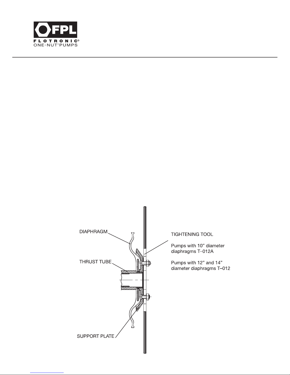
FITTING REINFORCED DIAPHRAGMS
On pump applications that cause a positive pressure greater than 2 bar to act on the diaphragm
wetted face when supporting air pressure is not present, e.g. in CIP or high suction head systems,
reinforced diaphragms will normally be specified. The exception is when a Guardian or Sentinel
diaphragm protection system is fitted.
The reinforced diaphragm package consists of a pair of standard diaphragms,with support plates and
requires a thrust tube specific to this arrangement.
To fit reinforced diaphragms, first follow the instructions for standard diaphragms as for procedures 1 to 6
on page 14. It should be noted that the thrust tube threads will protrude further through the diaphragms
than on a standard version.
After the diaphragms have been correctly tightened, each support plate in turn should be offered
onto the thrust tube thread and fully tightened against the rear face of the diaphragm using tool
Part No. T-012 for pumps with 12” and 14” diameter diaphragms or T-012A for pumps with 10”
diameter diaphragms respectively. Ensure that the two grub screws supplied with each support plate
are removed or fully retracted for this stage.
When the support plates have been correctly fitted, fit the grub screws using a thread locking adhesive
and tighten until they are flush with the rear of the plates.
16
Servicing & Diaphragm
Fitting Instructions
Page 25
Before carrying out these processes it may be necessary, and is certainly advisable, to change the divider
seal fitted in the centre section of the pump body. To carry out this procedure, refer to the individual
section covering the model of pump being serviced.
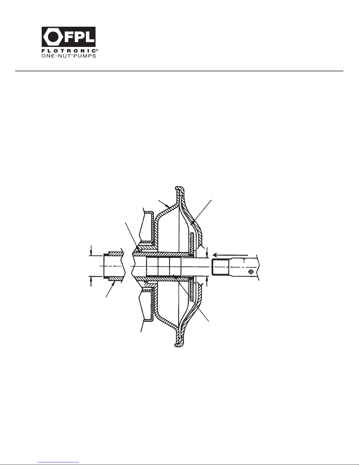
TIE ROD REASSEMBLY
When the pump is being reassembled on the horizontal centre line, the tie rod must be inserted into
the end of the thrust tube that is closest to the bearing end. See drawing below. If the pump runs for
one stroke and will not then move, the tie rod has been inserted incorrectly.
The above comment applies to standard and also pumps fitted with extra diaphragms for rupture
protection systems (see Sections 6, 10 & 18).
17
Servicing & Diaphragm
Fitting Instructions
Diaphragm
Pump Body
Seal
Enter Tie Rod
into thrust tube
at bearing end
Smaller
diameter hole
Bearings
Thrust
Tube
Larger
Diameter
Hole
Note:
A suitable anti-seize compound, either standard or food-quality should be applied to the tie rod thread to
aid tightening and removal of the large nut. (Example - ‘Never Seez’ from Bostik.)
Page 26
18
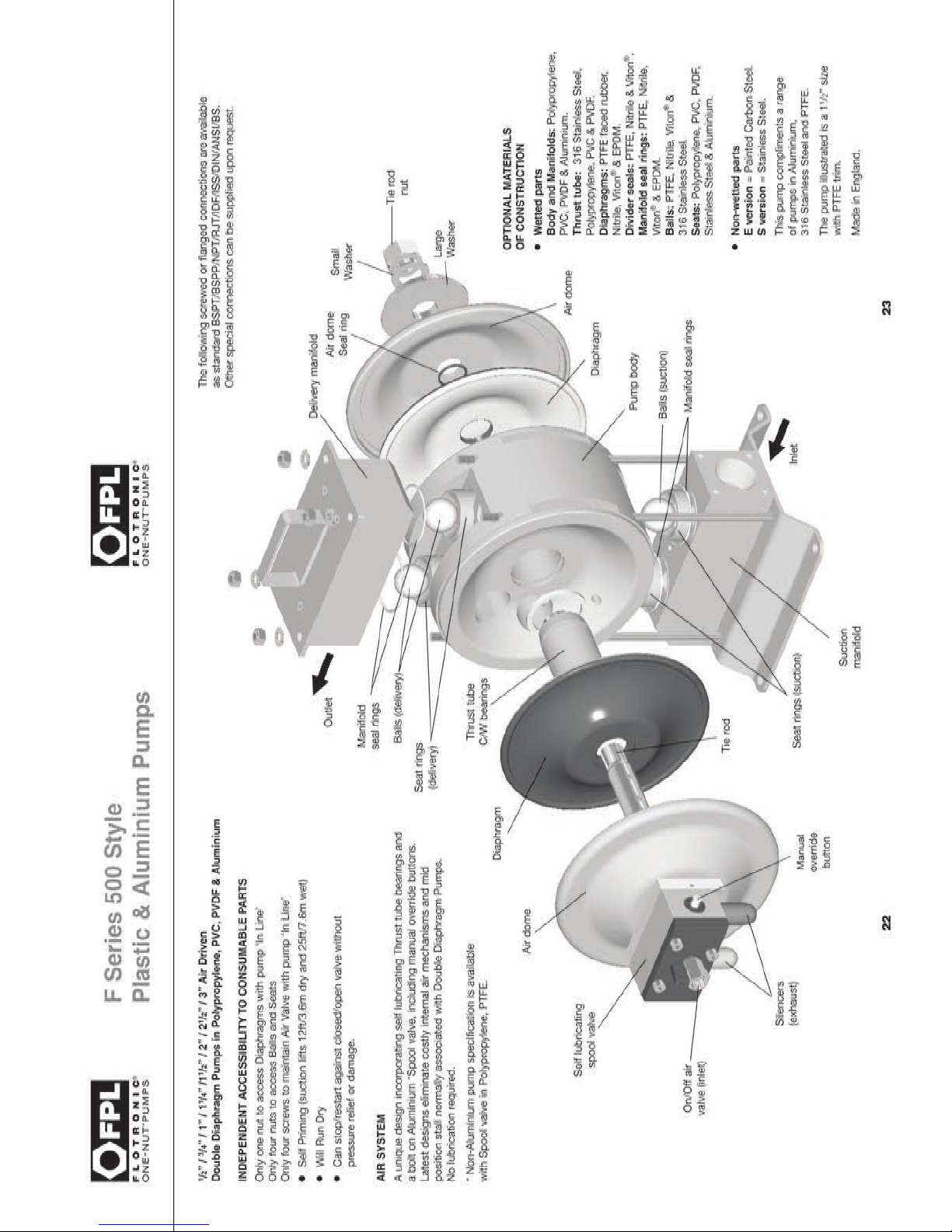
F Series 500 Style
Plastic & Aluminium Pumps
Section 11 - F Series 500 Style Plastic & Aluminium Pumps
Page 27

Section 11 - F Series 500 Style Plastic & Aluminium Pumps
All previous maintenance instructions up to & including Section 10 apply to F series 500 style pumps but
in addition, the following procedures apply.
PUMPS WITH 7”, 10” AND 12” DIAMETER DIAPHRAGMS
First the large main nut on the horizontal centre line assembly must be slackened. Access to balls and
seats can be made with the pump standing on its base plate but disconnected from adjacent pipe-work.
Remove the delivery manifold by first undoing the nuts and removing washers on the long studs which
pass through the complete pump assembly.
Pulling the delivery manifold assembly upwards will expose the balls, seats and manifold seals for cleaning
and replacement as required.
Lift the body section upward on the studs to expose inlet balls, seats and seals for cleaning and
replacement as required.
Reassemble in reverse order ensuring that the assembly is true and square before replacing and
tightening the four top nuts & washers. Refer to Section 8 for torque figures. Tighten nuts in rotation and
diametrically opposite when reassembling. On pumps with 12” diameter diaphragms ensure that the
side support plates are re-fitted.
This operation can be carried out independently of the earlier instructions concerning horizontal centre
line, diaphragm components etc. subject to slackening and re-tightening the main nut as paragraph
1 above.
Divider seals on this model are of two types. If the pump is fitted with a stainless steel thrust tube,
then the replacement of the divider seal should be made by first prizing out the old divider seal using
a sharp knife or pointed instrument. Then carefully cleaning the groove to ensure that repositioning of a
new divider seal can be made easily.
Having ensured that the groove is thoroughly clean, grip the outer periphery of the seal between the
thumb and forefinger in one hand, then using the thumb and the forefinger of the other hand, grip the
outer periphery at right angles to the existing grip.
19
F Series 500 Style
Plastic & Aluminium Pumps
Page 28
While gripping the seal, twist the seal so that the face can be inserted into the groove. Then work the
remainder of the seal into the groove, finally pushing the seal down with a wooden handle from a
screwdriver or similar. Care should be taken not to damage the seal while this operation is carried out.
Having fitted the new seal, reassembly of the horizontal centre line components can be carried out by
pushing the thrust tube and diaphragm assembly through the new seal. When tension divider seals
are fitted and stainless steel thrust tubes, use the plastic nose cone (Supplied with pump - if in doubt
contact FPL), to aid assembly.
On pumps fitted with polypropylene or other types of sleeve, the divider seal groove is elongated in an
eccentric manner in the top radius.
Removal of the old seal is carried out by first pushing the seal upwards into to this elongated area as far
as it will go, and then prizing out the lower edge and extracting the old seal.
Having ensured that the eccentric groove is completely clean, refit the new divider seal in the reverse
manner. The new divider seal will have been stretched on to a keeper disc and this disc should be
removed before attempting to fit the new seal. Having fitted a new seal, the thrust tube and diaphragm
assembly should be inserted as quickly as possible to prevent the divider seal contracting.
See Drawing Below:
20
F Series 500 Style
Plastic & Aluminium Pumps
Keeper Disc
when fitted
Divider Seal
Insert Divider
Seal into top
of groove
Then - slide
into bottom
of groove
Page 29

Thrust tube sleeves may be either welded together permanently or alternatively, may have an inner ‘O’ ring
inside the sleeve. Removal of this ‘O’ ring and replacement can be carried out by pulling the two halves
of the thrust sleeve tube apart, prizing out the old ring and fitting with new components supplied.
PUMPS WITH 14” DIAMETER DIAPHRAGMS
All above instructions apply except that the through studs passing through the pump body are in two
sections,and are replaced by bolts screwing into four horizontal bars inset into the pump body.
These bolts must be unscrewed from the top plate and footplate to obtain access to the balls and seats.
Refer to Section 8 for torque figures. Bolts must always be tightened in rotation to ensure that
manifolds are pulled down true and square to avoid subsequent leakage.
21
F Series 500 Style
Plastic & Aluminium Pumps
Page 30
Page 31
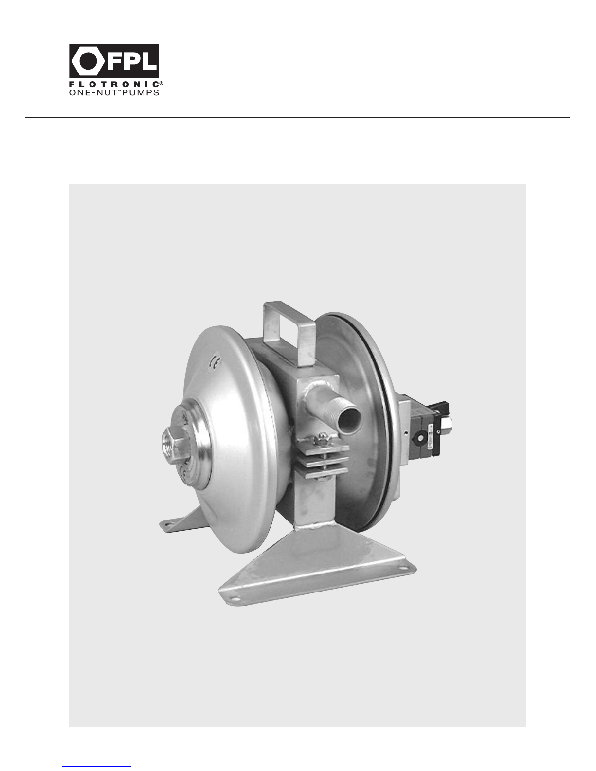
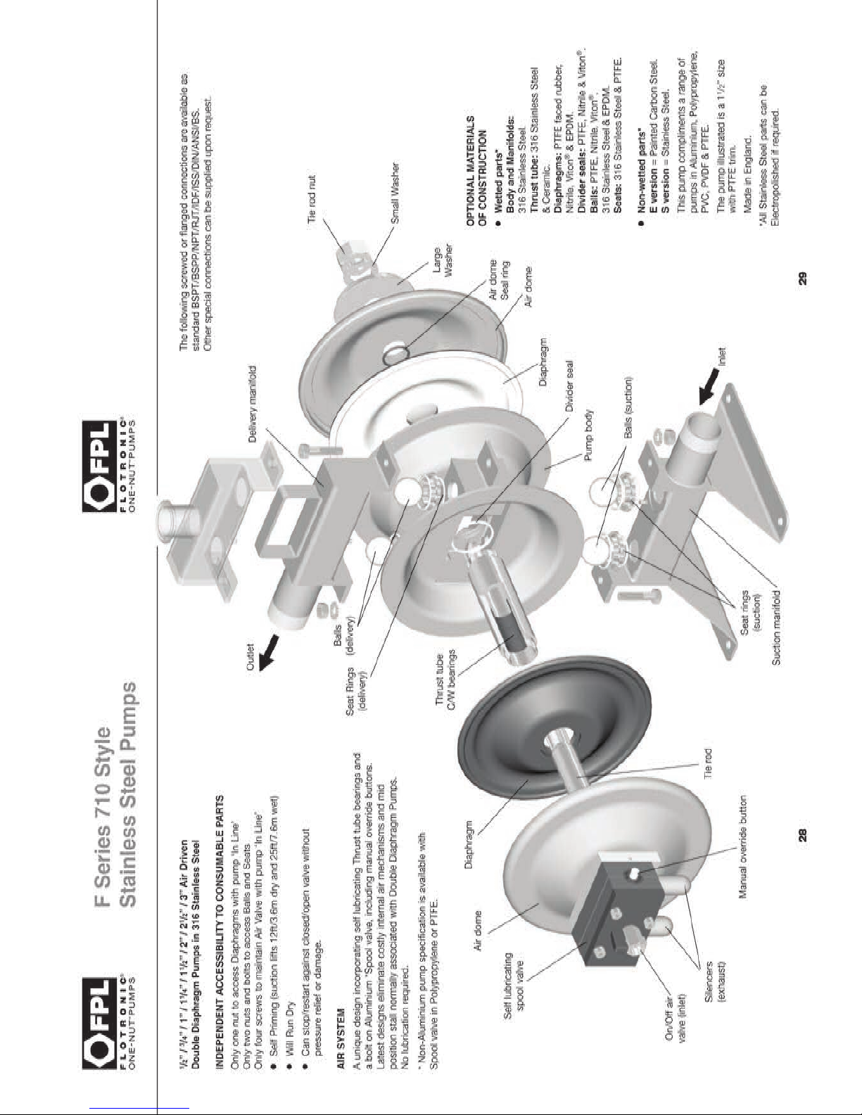
F Series 710 Style
Stainless Steel Pumps
24
Section 12 - F Series 710 Style Stainless Steel Pumps
Page 32

25
F Series 710 Style
Stainless Steel Pumps
Section 12 - F Series 710 Style Stainless Steel Pumps
All previous maintenance and other instructions up to and including Section 10 given earlier apply to
F Series 710 style pumps. In addition, the following procedures apply.
Access to valves and seats is carried out by first disconnecting process pipe-work and undoing the
two or four bolts which connect the suction and delivery manifolds together, and which are located
between the pumping chambers and adjacent to the outside body of the pump.
The operation should preferably be done with the pump upside down and suitably supported.
This enables the suction and delivery manifold to be removed without causing the balls inside the
pump to fall out and perhaps become damaged during disassembly.
After unscrewing the bolts referred to above, the suction manifold can be removed, exposing the
two seats and allowing the suction balls to be seen, which will be inside the pump body. The two
delivery seats and delivery balls will be inside the delivery manifold. The balls will be removed from
the delivery manifold by turning the manifold, and the suction balls can be removed by turning the
pump the right way up allowing them to drop out. In circumstances of slight expansion, balls may
be eased out using a blunt tool.
New balls and seats should be fitted when necessary and to reassemble, the reverse procedure is
adopted making sure the manifold is clean and free from obstruction.
Note:
Care should be taken to reassemble the pump body the right way up. Valve balls should be situated
within the guide wires - two in the body and two in the delivery manifold.
Note:
On 2” & 3” pumps with 14” diameter diaphragms, because of the metal support bar across the top of
the pump body, it is sometimes easier to support the delivery manifold balls on a thin plate or card which
can be withdrawn once they have been placed into position inside the manifold.
The pump can be reassembled using horizontal centre line parts in the manner described earlier.
If the pump is fitted with PTFE divider seals, proceed as shown on drawing overleaf.
Page 33
26
F Series 710 Style
Stainless Steel Pumps
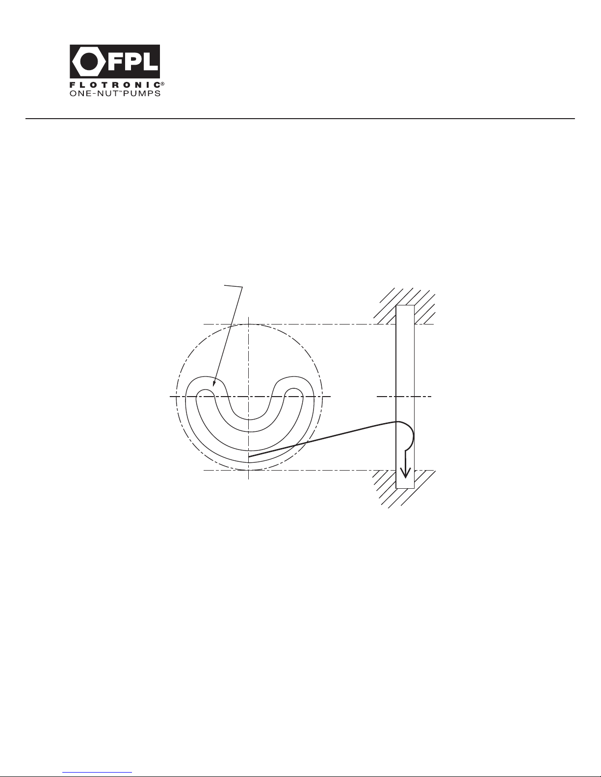
PROCEDURE FOR FITTING DIVIDER SEAL (PTFE)
Divider seals can be fitted into F Series 710 Style pumps with 10” diameter diaphragms. First prise out
the old divider seal from the groove in the centre of the pump body, and refitting, by inserting a new
divider seal up into the inner groove as far as possible by bending the new seal into position.
FIRST, BEND NEW CIRCULAR DIVIDER SEAL AS SHOWN:
Having been fitted, the divider seal should be pushed into place using the handle of a screwdriver or
similar tool, which should not allow damage to occur to the new seal. The thrust tube can then be inserted
as earlier described.
First, bend new circular
divider seal as shown;
Page 34
27
F Series 710 Style
Stainless Steel Pumps
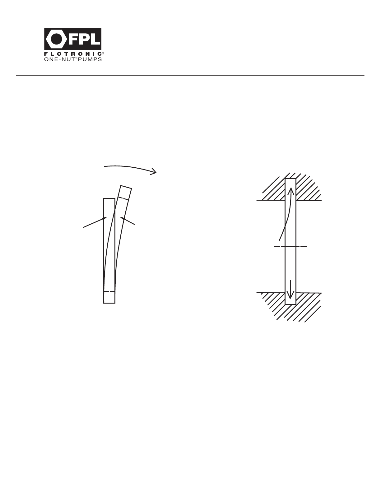
On 2” & 3” F Series 710 Style pumps with 14” diameter diaphragms the divider seal assembly is in two parts.
On one side of the body there is an elongated groove containing a flat seal which can first be removed
by sliding the seal upwards into the elongated section of groove, then by gripping the lower part of the
seal, it can be pulled out.
Replacement of a new seal is the reverse of the above. See drawing below:
The second seal consists of a split PTFE bearing of ‘c’ section which can be prised off the wall of the pump
body using a screwdriver or similar and replaced by hand.
When reassembling the pump, it is preferred that this bearing is at the front nut end of the pump, as this
bearing is provided to resist the torque that is applied to the tied rod assembly when the nut is tightened.
Keeper Disc
when fitted
Divider Seal
Insert Divider
Seal into top
of groove
Then slide into
bottom
of groove
Page 35
Page 36
30
F Series
Good Food Style Pump
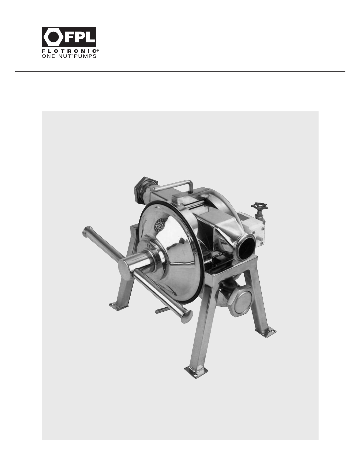
Section 13 - F Series Good Food Style Pump
Page 37

31
F Series
Good Food Style Pump
Section 13 - F Series Good Food Style Pump
All previous maintenance and other instructions up to and including Section 10 given earlier, apply to the
F Series Good Food pumps. In addition, the following procedures apply.
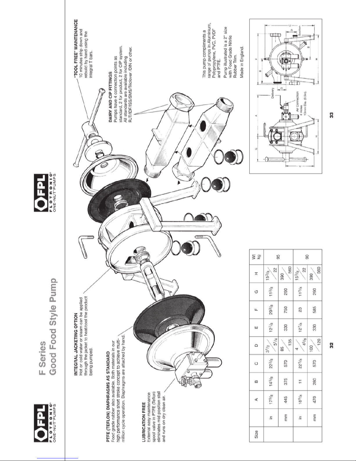
Access to valves and seats is carried out by first disconnecting process pipe-work and undoing the
top and bottom handles which screw through the cross bar across the top and bottom of the pump.
Simply take hold of the handle and turn anti-clockwise to undo. Once loose, the manifold can be
removed to one side of the pump.
Note: On pumps with 14” diameter diaphragms it may be necessary to remove the blanking nut and cap
on one end of the manifold to allow it to pass through between the body chambers on removal.
Once the manifold is free of the pump, simply twist the seat ring anti clockwise to unlock it with its two
‘O’ rings from the manifold retaining lugs.
In circumstances of slight expansion, balls may be eased out using a blunt tool.
New balls and seats should be fitted when necessary and to reassemble, the reverse procedure is
adopted, making sure the chambers are clean and free from obstruction inside the pump manifolds.
The pump can be reassembled using horizontal centre line parts in the manner described in the F Series
710 Style pump, Section 12.
F Series Good Food Style pumps use the split PTFE bearing type of divider seal.
The bearings are of PTFE in a ‘C’ Section which can be prised off the wall of the pump body using a screw
driver or similar object, and they are simply and easily replaced by hand.
Note:
A suitable food-quality anti-seize compound should be applied to the tie rod thread to aid tightening and
removal of the large nut. (Example ‘Never Seez’ from Bostik)
Page 38
Page 39

Cleaning Procedures
FPL pumps for food and pharmaceutical applications have been designed to minimise areas where
soils can accumulate with consequent user problems.
Areas, which may be liable to accommodate soils, include the connecting faces between diaphragms
and pump body and the divider seal and bushes where fitted.
However these areas are easily accessible due to the one nut and easy access designs of the pump.
CIP (Cleaning in place) can be performed on FPL pumps subject to FPL being aware of this requirement
at time of order and the correct diaphragms being fitted by user when replacement is necessary.
Diaphragms must have a backing plate to support them under CIP loads.
It is strongly recommended that the pump shall be left running, with a minimum air pressure of 2 Bar
(29 psi) while CIP cleaning is carried out. This will assist cleaning the internal areas and prolong
diaphragm life.
It must be noted that when a diaphragm eventually fails in service, product contamination will occur on
contact with the air system.
Most users of pumps on CIP duties will have their own procedures for CIP cleaning.
These may include caustic and antiseptic washes and final rinse hot and cold washes.
It is most important that final washes should be of sufficient time to ensure cleanliness and sterilisation
of all internal areas.
If process conditions are such that CIP cleaning procedures may not be adequate then the pump must
be dismantled and components washed and sterilised by hand and final washes applied again after
assembly. Parts are suitable for industrial autoclaves.
FPL cannot advise on procedures for CIP or sterilisation procedures.
After CIP final wash some liquid will remain in the bottom of pump chambers. Body designs are
available on request to minimise this liquid but are not supplied as standard. This liquid will be in contact
with the product being pumped when the system is operated.
34
F Series
Good Food Style Pump
Page 40
35
F Series
Slim Style Metallic Pumps
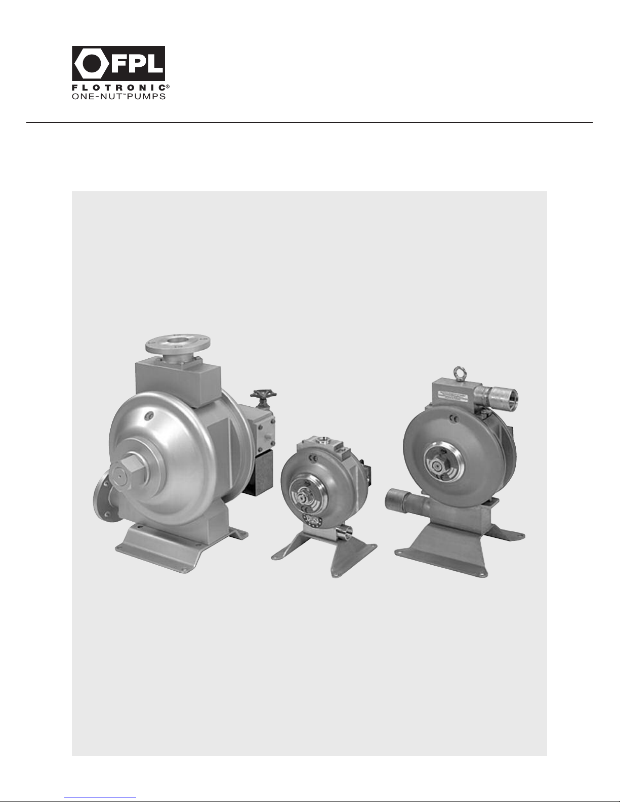
Section 14 - F Series Slim Style Metallic Pumps
Page 41

Section 14 - F Series Slim Style Metallic Pumps
All previous maintenance and other instructions up to and including Section 10 given earlier apply to
F Series Slim Style Metallic Pumps. In addition the following procedures apply.
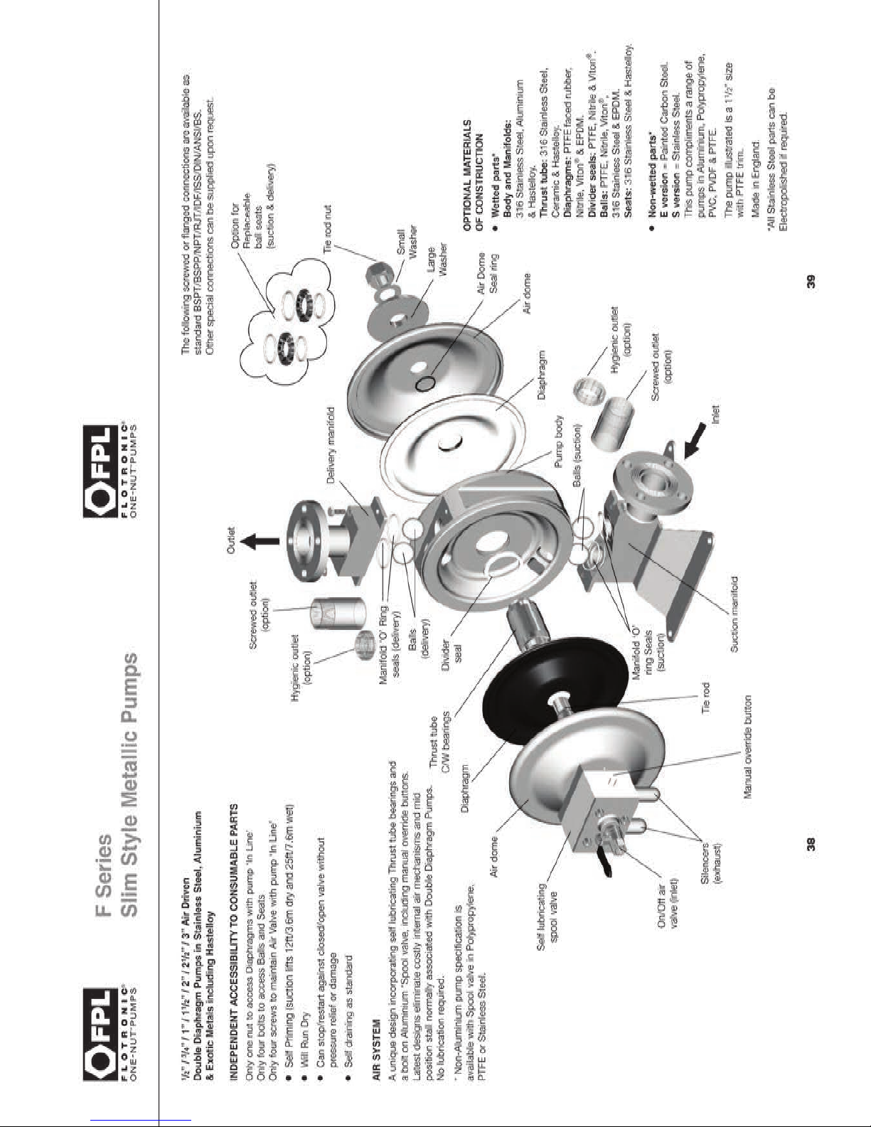
After disconnecting the process pipework, access to the delivery and suction valve balls for inspection
and replacement may be achieved as follows.
NON SEATED VERSIONS
Remove the two bolts attaching the delivery manifold to the pump body. Detach the manifold exposing
the balls and also the ‘O’ ring seals which remain contained in their manifold grooves.
For access to the suction valve balls, the following procedure should be adopted for which it will be
found easier to work with the pump inverted although this is not essential.
On pumps up to 1” fitted with 7” or 10” diameter diaphragms, there are two central attachment bolts which
pass through the footplate and manifold into the body. Once these are removed the manifold can be
detached complete with the footplate exposing the suction balls and ‘O’ rings. Again the ‘O’ rings will
be contained in their manifold grooves.
On 1
1
/2” and 2” pumps with 10” diameter diaphragms, the attachment bolts are positioned through
protruding lugs on the ends of the manifold. On 2” pumps with 12” diameter diaphragms, there are
four outer bolts that pass through the footplate.
SEATED VERSIONS
After unscrewing the bolts referred to, the delivery chamber can be removed, exposing the two seats
and allowing the delivery balls to be seen, which will be mounted on the body. For access to the suction
valve balls and seats it will be found easier to work with the pump inverted although this is not essential.
New balls and seats should be fitted when necessary and each seat has two ‘O’ rings fitted which should
be changed as required. To reassemble, the reverse procedure is adopted making sure the chambers are
clean and free from obstruction.
Re-assemble the pump in reverse order tightening the bolts to the torque specified in Section 8.
To replace the divider seal, follow the instructions given for the F Series 500 Style pump in Section 11.
36
F Series
Slim Style Metallic Pumps
Page 42
BODY AND MANIFOLD DRAINING
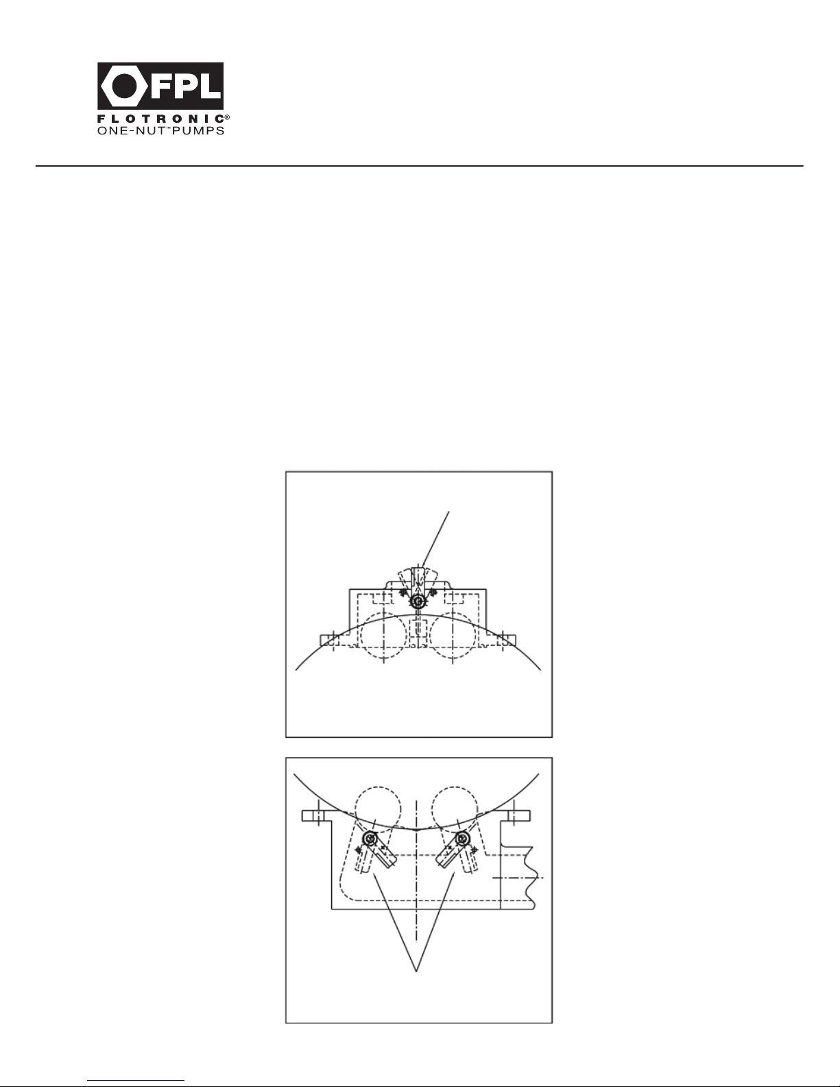
Suction and delivery valve ball lifters may be fitted to F Series Slim Style metallic pumps as an option
where rapid pump draining is required.
On pumps fitted with this option there are external levers for operating the suction and delivery valve balls.
The levers must be turned to the “run” position for normal use and turned to the “drain” position to lift
the valve balls only when the pump is not running.
The valve ball lifter spindles are each retained with a securing nut which should remain tightened to a
torque of 3 Nm (2.2 lb/ft ) to prevent leakage. A second nut on each spindle is provided to secure the
operating lever and should also be tightened to a torque of 3 Nm (2.2 lb/ft).
37
F Series
Slim Style Metallic Pumps
Fig. 1
Fig. 2
BALL LIFT LEVER
TYPICAL F SERIES SLIM STYLE
DELIVERY MANIFOLD
TYPICAL F SERIES SLIM STYLE
SUCTION MANIFOLD
BALL LIFT LEVERS
Page 43
Page 44
40
F Series ‘K’ Style
Chemflo All PTFE
Section 15 - F Series ‘K’ Style Chemflo All PTFE
Page 45

41
F Series ‘K’ Style
Chemflo All PTFE
Section 15 - F Series ‘K’ Style Chemflo All PTFE
All previous instructions up to and including Section 10 apply in addition to the following:
ACCESS TO VALVES AND SEATS
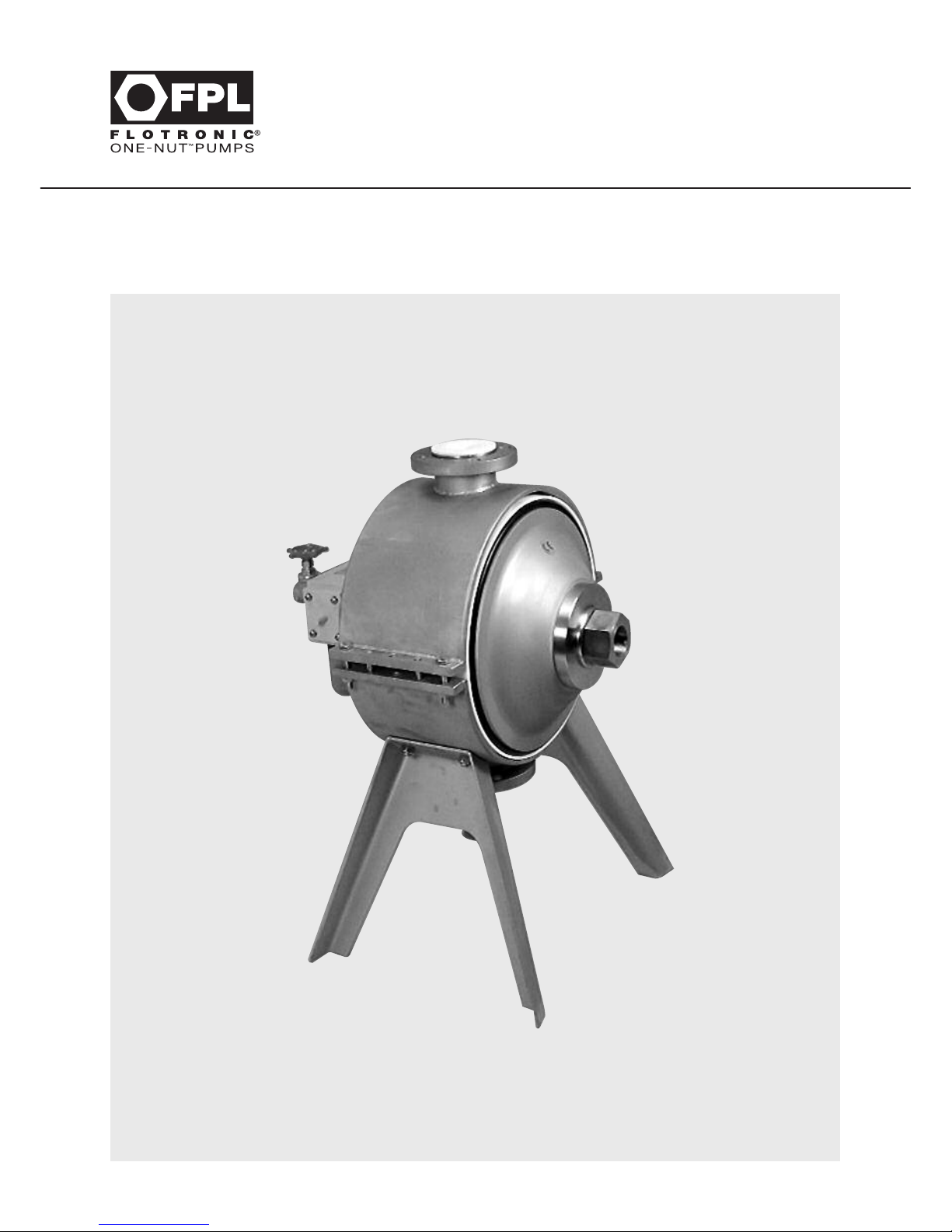
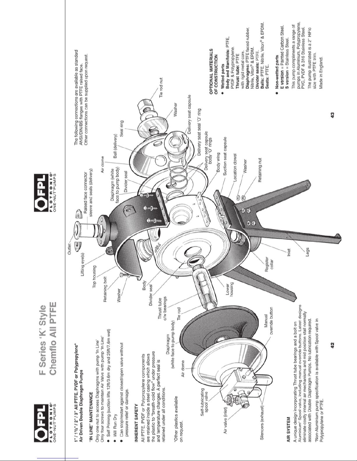
The air system, both diaphragms and thrust tube must be removed as in Section 10.
Disconnect the process pipework from the pump and remove the suction and delivery connector sleeves.
Care must be taken to avoid damaging the sealing face when prizing the raised face from the metal flange.
Undo the three clamping bolts on each side of the housing loosening gradually and evenly. The upper
housing will tend to rise slightly due to pressure from the seat plug springs. Remove the upper housing
leaving the body sitting in the lower housing.
The delivery seat plug assemblies can now be removed with the aid of the seat dismantling tool T-014
which is attached to the pump support leg. Insert the tool through the delivery port and gradually lever
the seat plug and ball from the body taking care not to damage the port. Remove the seat plug assembly
when released from the body. The seat platform may remain in the body and require removal separately,
when it should just lift free. This seat is located to the plug with a dowel and may be replaced if worn
or damaged. Repeat for second delivery seat plug assembly.
To access the suction seat plug assemblies for removal, proceed as follows: Lift the body from the lower
housing, invert it and carefully re-position into the housing engaging the delivery port over the suction
body register collar. This will provide a stable location for the body whilst work is carried out on the
suction seat plugs.
To remove the suction seat plug assemblies, repeat the procedure as for the delivery plug but insert
the dismantling tool through the body windows to gain access and gradually lever the plugs as before.
When the seat plug assemblies and seat platforms have been removed the components can be
inspected and replaced as necessary. The two seat plug inner ‘O’ rings should receive particularly careful
attention and the single larger outer ‘O’ ring should always be replaced for reassembly.
With the body still inverted in the lower housing, re-fit the suction seat plug assemblies after first
applying grease to the domed hexagon bolt heads then invert the body to its original operating position
ensuring that the suction seat plugs do not drop out. The body may then be located in the lower housing
ensuring that temporary support is given at this stage to keep clear of the suction body register collar.
This may be achieved by inserting the housing clamp nuts between the suction housing grip bar and
the body side support plates. Replace the delivery balls and seat plug assemblies repeating the suction
plug procedure.
Page 46
Page 47

44
F Series ‘K’ Style
Chemflo All PTFE
The temporary supporting nuts can be removed to allow the body to locate in the lower housing
carefully aligning the suction port on the suction body register collar. Note the body may not locate fully
at this stage due to the suction seat plugs standing proud. Apply grease to the domed hexagon bolt
heads on the delivery plugs and replace the upper housing carefully engaging the delivery body register
collar into the delivery port. Replace the six clamp bolts and nuts and tighten down gradually and evenly
to the torque stated in Section 8. As a visual check at this stage, the housing grip bars should clamp
the body side support plates with no gaps.
Re-assemble the suction and delivery connection sleeves into the housing ensuring replacement of the
‘O’ rings. Note that the suction sleeve is shorter and marked ‘BOT’, the delivery sleeve being longer
marked ‘TOP’, inserting the large ‘O’ rings into the body apertures. Carefully align the seat plug dowel
and push the assembly home through the ‘O’ ring, giving a gentle tap on the dome head hexagon of
the spring retaining bolt if necessary to ensure full engagement. The dismantling tool may be used in the
slot provided to aid orientation of the plug. Note that the plug will stand slightly proud due to the new
‘O’ ring not having been compressed.
CHANGING DIVIDER SEALS
New divider seals should be fitted to the body before replacement. (Two are fitted). See F Series 500 Style
pumps, Section 11 for full details.
Page 48
45
Air Valves
Section 16 - Air Valves
Page 49

Section 16 - Air Valves
This section is common to all pumps.
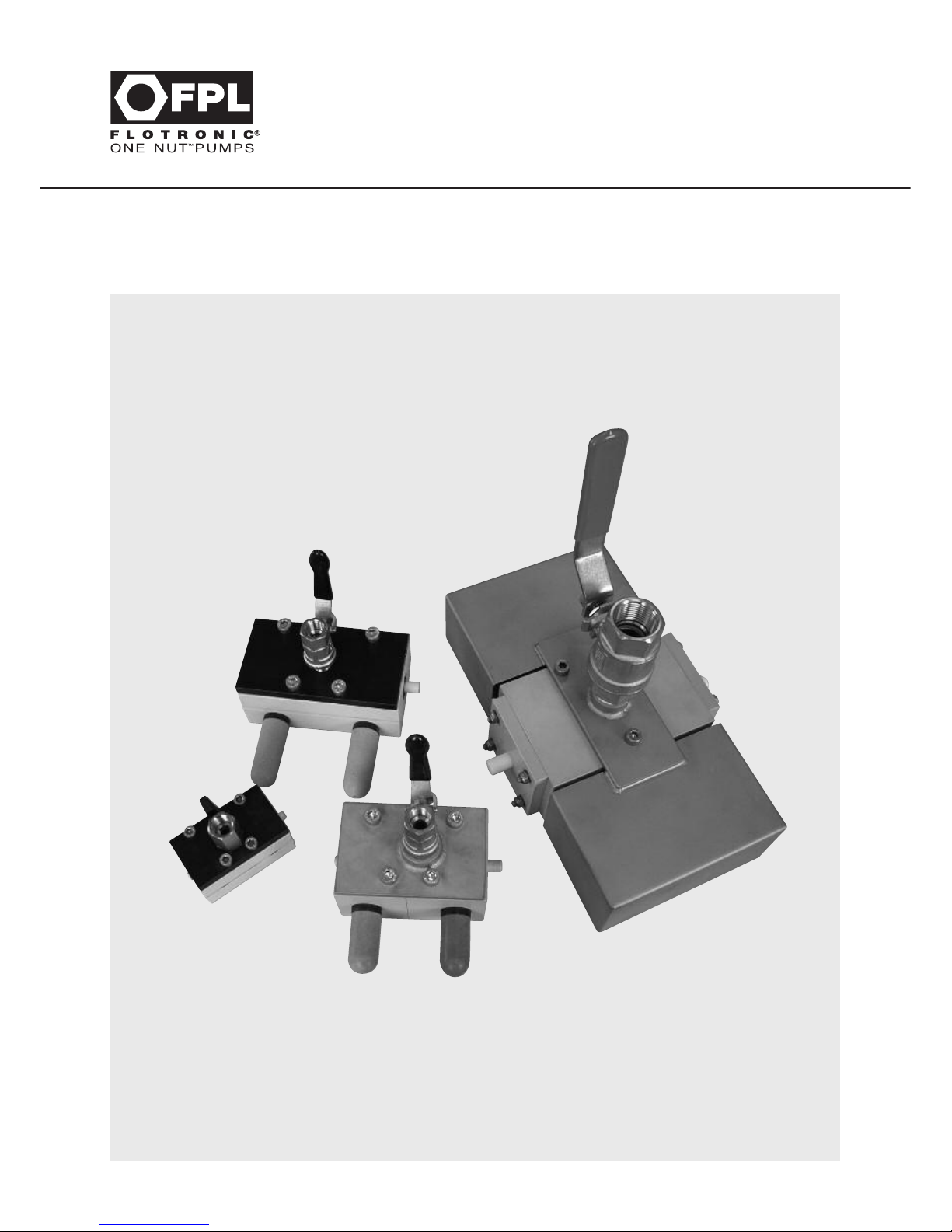
All air valves are bolted to a mounting plate using either 3 or 4 bolts which, after removal, will allow the
air valve to be examined in detail. Note that there will be ‘O’ ring seals and jointing materials between
the air valve and the plate which should be examined and replaced if necessary.
It is recommended that air valves, after removal, should be discarded completely and replaced with a
new valve assembly. However, should it be found expedient to service the valve then service kits can
be obtained from FPL, dependent upon the model and style specified.
On pumps with 7” or 10” diameter diaphragms the valve will contain a stainless steel perforated tube
inside which is an acetal spool which carries the sealing rings. Access to the valve component is made
by two methods.
If the body is of painted aluminium it will be found to be in three parts, the top cover plate and two
clamping sections which contain the stainless tube. To remove this stainless tube, grasp the two white
buttons at either end of the tube and lift out the complete assembly. Replace with a new assembly.
Note that the rubber moulded seal which contains this tube is off-set and will only fit in one position;
take care to ensure that it is correctly fitted.
For all other ISO2, ISO3 and ISO4 air valves the removal of two screws at one end of the body followed
by pulling the two halves of the body apart will expose the tube. ‘O’ ring seals are contained inside
the two halves of the body and these seal the stainless perforated tube once it is pushed back in to the
two body halves and reassembled. It should not be necessary to replace these seals unless aggressive
chemical attack has taken place, in which case the complete assembly should be discarded
and replaced.
Under no circumstances should the spool from the above configurations of air valve be pushed out
of the stainless tube as this is a throw away item and cannot be overhauled.
On pumps with 12” and 14” diameter diaphragms, access to the centre spool is made by removing
the two end caps and pushing the spool out, the spool being made of acetal and carrying the sealing
rings. A new spool assembly can be obtained from FPL and should be inserted carefully back into the
perforated tube which is not removable.
Be sure that all ‘O’ ring seals are refitted, and that all ports and apertures are clean and clear before
the assembly is rebuilt and replaced on to the pump.
Clean dry air is preferred and lubrication is not essential, but can be applied.
46
Air Valves
Page 50
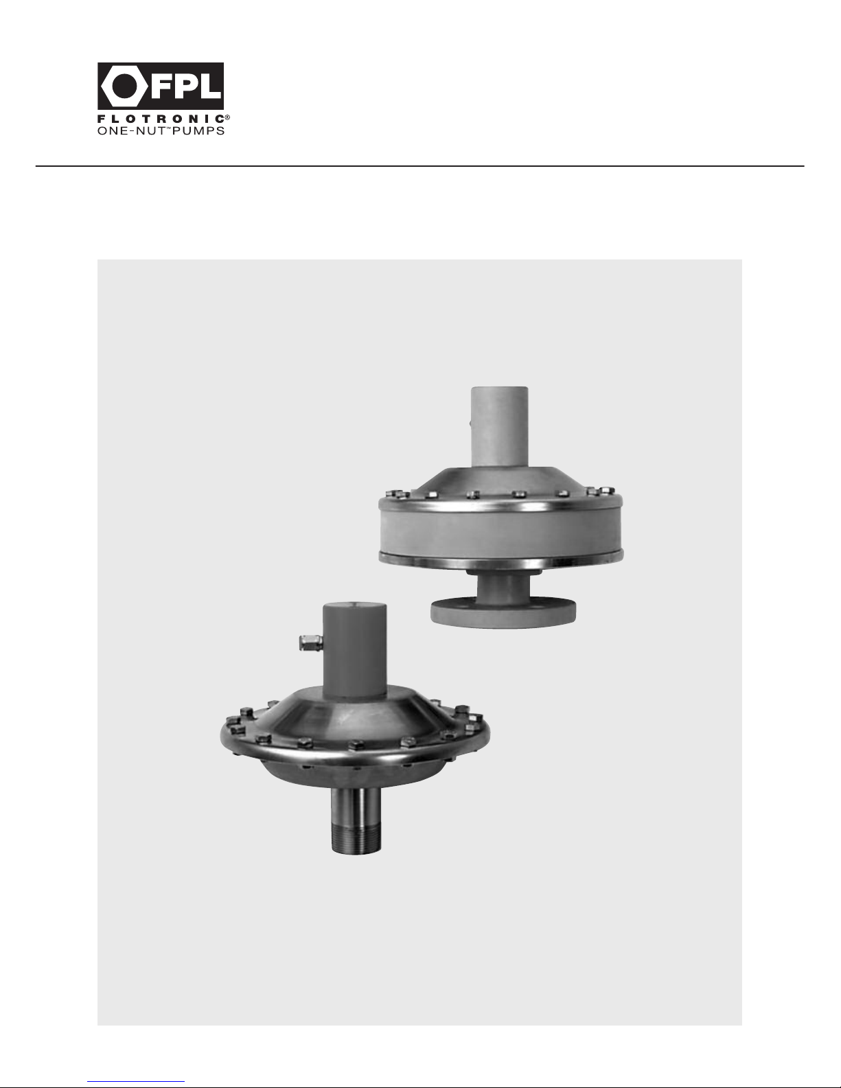
47
Pulsation Dampers
Section 17 - Pulsation Dampers
Page 51

Section 17 - Pulsation Dampers
This section is common to all pumps.
Pulsation dampers are obtainable to be fitted to FPL pumps but vary depending upon the individual
model considered.
The maintenance instructions given below apply to all models, although the mounting of the damper on
to the pump may vary slightly.
MAINTENANCE
Before carrying out any maintenance or servicing, the air system must be isolated and the connections
disconnected from the process line. If integral, turn off air supply at the pump. If separate, disconnect
from the supply located at the side of the spool valve on top of the damper.
DISASSEMBLY
Use an M5 allen key to remove the socket cap screws holding the spool valve in position. This will enable
you to remove the spool valve.
Undo the 16 nuts and bolts around the damper and remove the air dome. This exposes the PTFE
faced diaphragm with spool valve rod attached. Place the rod into a vice fitted with soft jaws and unscrew.
48
Pulsation Dampers
Page 52
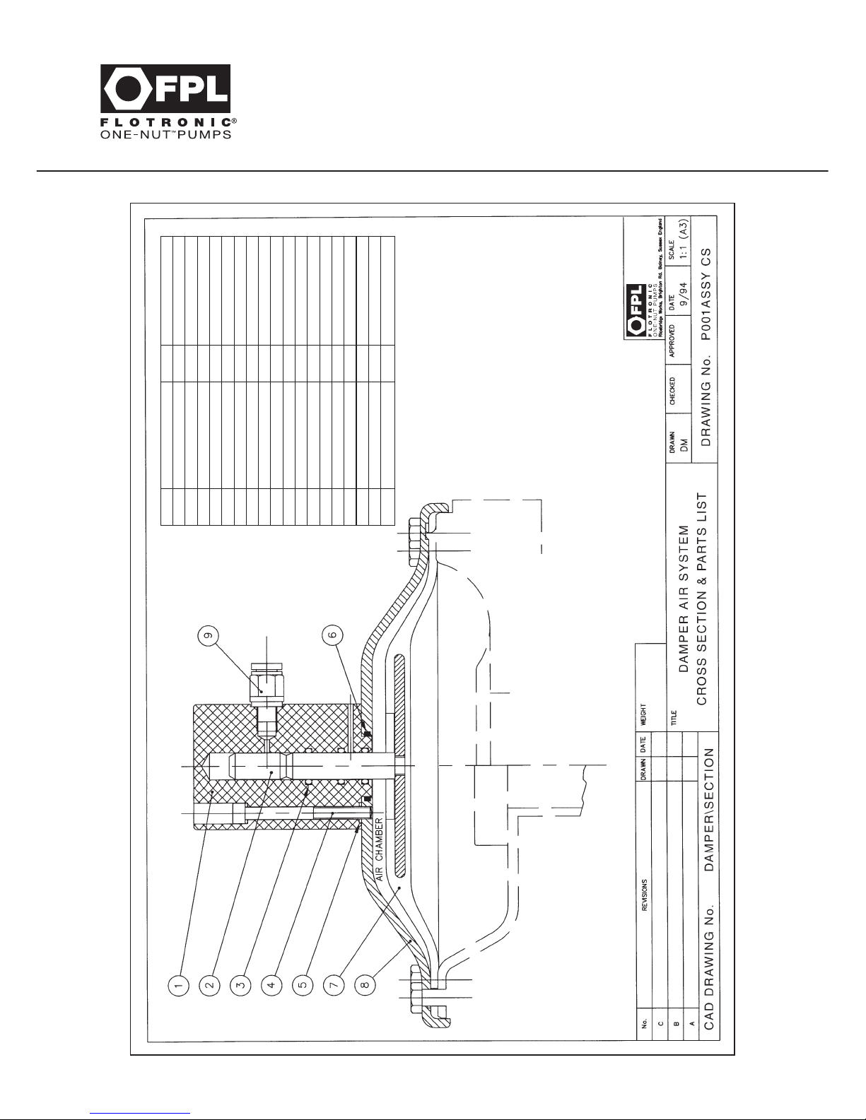
49
Pulsation Dampers
FLUID CONTAINMENT
316 STAINLESS STEEL
POLYPROPYLENE
PVC
PVDF
PTFE
ANTI-STATIC PTFE
ITEM DESCRIPTION Qty. MATERIAL
1 SPOOL VALVE BODY 1 POLYPROPYLENE
STAINLESS STEEL
2 SPOOL SPINDLE 1 STAINLESS STEEL
3 SPINDLE ‘O’ RING 4 NITRILE
VITON
4 BODY BOLT 2 STAINLESS STEEL
5 BODY BOLT SEAL 4 NITRILE
VITON
6 DOME ‘O’ RING SEAL 1 NITRILE
VITON
7 DIAPHRAGM 1 PTFE FACED
NITRILE
HIGH TEMP. NITRILE
VITON
EPDM
8 DAMPER AIR DOME 1 STAINLESS STEEL
CARBON STEEL
9 AIR CONNECTOR BRASS
Contact Flotronic Pumps Limited for a
complete range of material options.
Page 53
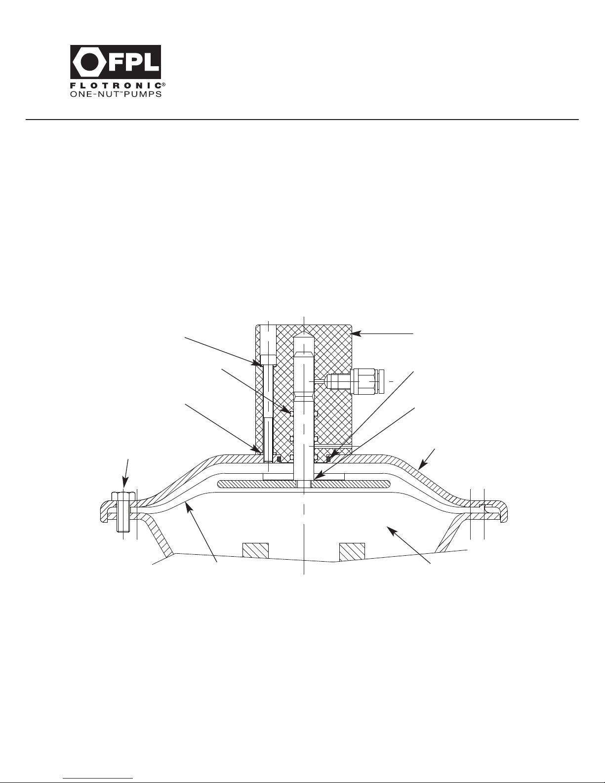
OPERATION
A back pressure may need to be applied downstream from the damper, of approximately 2 Bar, to achieve
the optimum damping effect.
Air may occasionally be expelled from the small bleed hole in the spool valve body; this is normal and
indicates that the damper is functioning correctly.
NOTE: Diaphragm failure on a damper is a rare occurrence, however, if it should occur process liquid
will be discharged from the bleed hole to atmosphere. If this potential discharge could be hazardous it
is recommended that a rupture protection system be fitted as described in Section 18 of this manual.
Maximum air supply pressure is 7.2 Bar
ASSEMBLY
Insert the spool valve rod into the diaphragm and tighten, securing with a small amount of thread
locking compound. Do not use serrated grips or other sharp objects as they will damage this rod.
Check that the ‘O’ rings are correctly fitted inside the spool valve body, if damaged these ‘O’ rings
must be replaced. Also verify that the air dome ‘O’ ring is fitted and undamaged. Insert the spool valve
rod / diaphragm assembly through the air dome and into the spool valve body ensuring first that the
fixing screw seals are in position and then tighten the two fixing screws. This assures correct location of
the air dome and diaphragm onto the wet dish.
Place this assembly on to the damper wetted chamber. For pump mounted versions, ensure that the
two screw holes for the spool valve are aligned with the pump manifold as this guarantees the correct
position of the air supply pipe. Replace the 16 nuts and bolts, using the torque figures stated in
Section 8. Finally reconnect the air feed pipework.
50
Assembly of New Diaphragm
Assemble bolts only following
careful alignment of air dome/
diaphragm and wet dish
Typical wet dish
Spool valve body
‘O’ rings
Spool valve body
Air dome ‘O’ ring
Spool valve rod/
diaphragm assembly
Air dome
Diaphragm
Fixing Screw Seal
Fixing Screw Seal
Page 54
51
Your Notes
Page 55
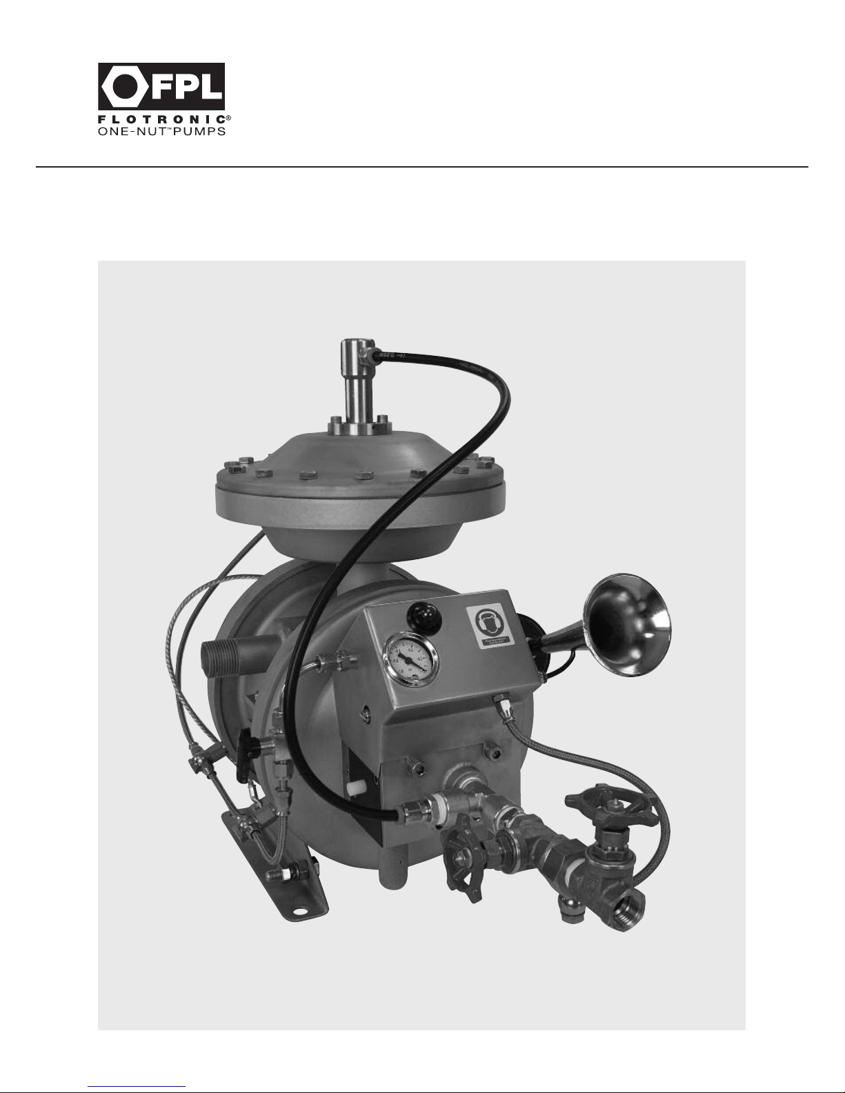
52
Rupture Protection Barriers
& Alarm Systems
Section 18 - Rupture Protection Barriers & Alarm Systems
Page 56

Section 18 - Rupture Protection Barriers & Alarm Systems
ALL PUMP SERIES
RUPTURE PROTECTION PACKAGE
INSTALLATION MAINTENANCE & OPERATION INSTRUCTIONS
The following instructions must be read in conjunction with the individual instructions relating to the
applicable Pump Series and apply to the horizontal centre line assembly only, as follows:
ACCESS TO DIAPHRAGMS
Before carrying out any maintenance or servicing, the air system and the connections must be
isolated from the process line.
To obtain access to the diaphragms and intermediate safety chamber, it is necessary to remove the
centre tie rod which carries the 5 port air system and air dome. This is carried out by unscrewing
the 1” nut on the end of the tie rod and, if necessary, restricting rotation of the air valve by gripping
the rectangular block to which it is attached, in a bench vice, incorporating soft jaws. Under no
circumstances should the 5 port air valve be held in a vice. During careful removal of the tie rod,
the dome at the nut end of the pump will be free and should be held and removed carefully without
damage to the integral ‘O’ ring, as the tie rod is withdrawn. Remove the diaphragms by prising away
the edge with fingers, (not sharp tipped tools), and rotate diaphragms anti-clockwise against each other.
A sharp tag should be sufficient to break the seal of one diaphragm, which can be removed by
unscrewing it anti-clockwise.
Carefully remove the outer separator ring, and prise out the seal retainer, located within the separator
disc against the back of the primary diaphragm. Carefully remove the ‘O’ ring over the thread, remove
the disc and unscrew the primary diaphragm.
Remove the entire twin pack diaphragm package from the opposite side, it will still be attached to the
thrust tube passing through the pump body. Place the thrust tube into a vice with soft jaws and
unscrew the package as previously described.
53
Rupture Protection Barriers
& Alarm Systems
Page 57
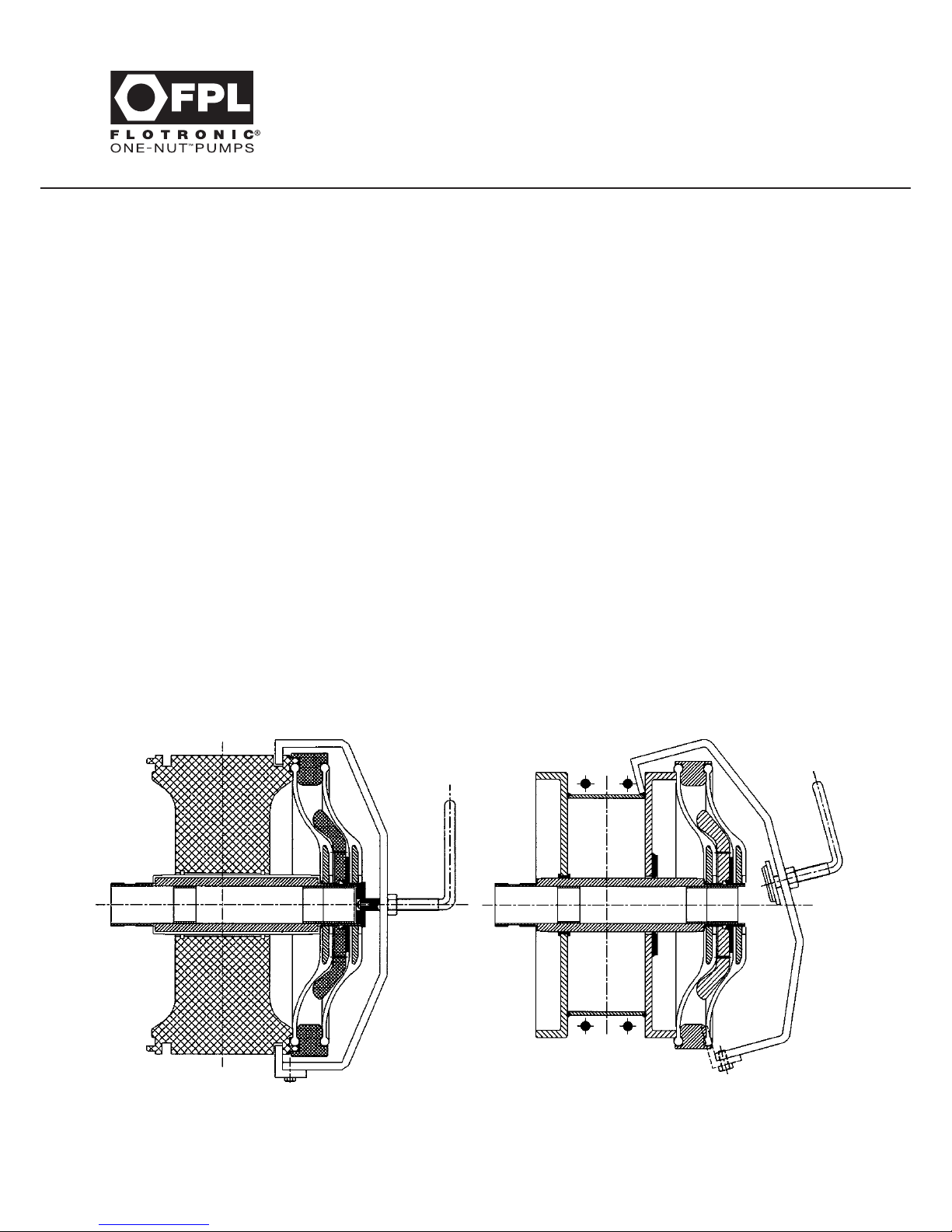
REASSEMBLY
Screw on the inner primary diaphragm to the thrust tube, which is still in the vice, push on the
separator disc and then the large ‘O’ ring, ensuring that the air vent grooves are positioned inwards
towards the back face of the primary diaphragm. Now push in the seal retainer. Position the
separator ring over the assembly to locate in the back bead of the primary diaphragm, ensuring
that this bead seal (integral with the diaphragm), is located into the recess provided on the ring.
Now screw on the back diaphragm ensuring that the PTFE white face is inwards.
If difficulty is experienced fitting the diaphragm, ‘flex’ the unit by immersing in hot, (but not boiling),
water for a few minutes. Under no circumstances should this diaphragm be fitted with the PTFE
(white) side facing outwards. Ensure that the connection tapping on the separator ring is in the correct
position for the Flotronic Sentinel Alarm System, or your own pressure switch if required/fitted.
All Pumps with 10” diameter diaphragms
Place the entire twin pack assembly into pump body and then open appropriate tool number B000,
B100 or B100H (B9000 Chemflo Pumps) fully, and grip around the assembly by clamping the tool
onto pump body rim (see sketch). Locate tool centre peg into the thrust tube hole showing at the
back of the diaphragm, and the screw down tool until diaphragms have been pushed through, the
first diaphragm of the opposite chamber, do not force the diaphragms through further than necessary
as this will shorten diaphragm life. Note that for the F Series ‘K’ Style Chemflo pumps the frame is
attached to the housing clamp bolt positions.
TYPICAL BARRIER TOOL APPLICATION
54
Rupture Protection Barriers
& Alarm Systems
Page 58

55
Rupture Protection Barriers
& Alarm Systems
Attach first primary diaphragm on opposite side, followed by separator disc, retainer, seal, separator
ring and finally, backing diaphragm (PTFE face inward). Tighten diaphragms by hand to achieve
positive seal. Do not use sharp edged tools. You cannot over-tighten diaphragms, a positive seal can
be achieved by hand tightening only.
Pumps with 12” and 14” Diameter diaphragms
Place the entire twin-pack assembly into the pump body and then lay the complete assembly, with
diaphragms, underneath onto tool No: B0009A.
Tighten down the fixing bars onto the slot in the body where the manifold normally fits. The diaphragms
will compress enough for you to now attach the opposite side diaphragms onto the top.
Complete the entire diaphragm tightening procedure on both sides and then insert the manifolds and
place the whole body/manifold/diaphragm assembly into the pump casing.
TIPS
1. After reassembly always ensure the diaphragm/thrust tube assembly is centralised in the pump body.
2. To rotate separation rings for a key-way alignment, pull away from wet diaphragm, thus transferring
friction forces from rubber to PTFE.
3. To remove last diaphragm from thrust tube, wrap a 12” long strip of 1” wide medium emery cloth
around the PTFE thrust tube mid-way along (to avoid divider seal region) with abrasive against the
PTFE. Grip in place tightly, using a jubilee clip with it’s screw knuckle on the lapped area of the
emery (for protection). Assemble the jubilee clip into a vice so that the screw knuckle acts as a stop
and so limits the necessary tightening of the vice.
Note:
This special tooling assembly is only necessary because of the special nature of environmentally
protected air driven double diaphragm pump. Normal 2 diaphragm Flotronic Pumps do not
require any special tooling to fit diaphragms.
Page 59
56
Your Notes
Page 60
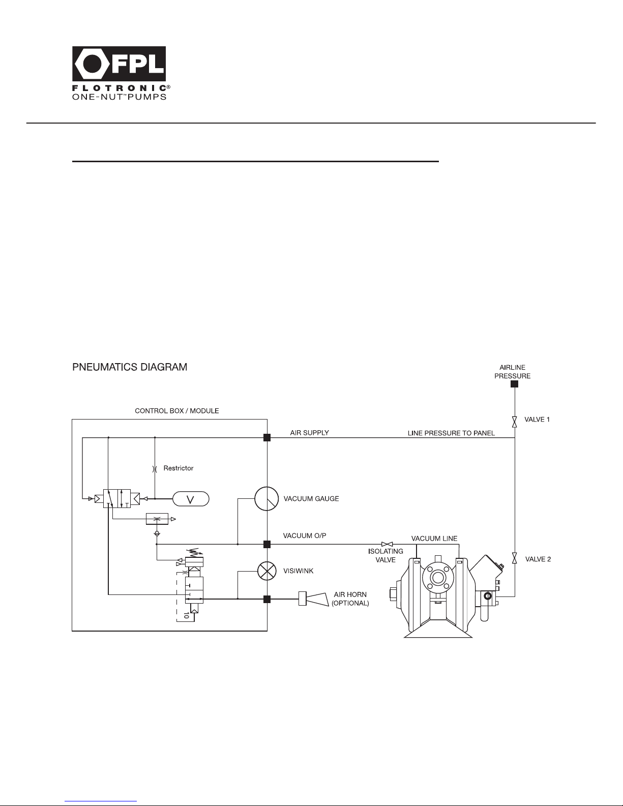
SENTINEL ALARM - OPERATING INSTRUCTIONS
1. Vacuum isolating valve must be open.
2. Air valves 1 and 2 must be closed.
3. Open air valve 1 to allow alarm unit to prime.
4. Alarm system is primed when vacuum gauge reading has stabilised at
approximately -0.8 bar dependent on air supply.
5. If vacuum of at least -0.2 bar is not achieved within 10 seconds,
the alarm will sound indicating a leak in the system.
6. Vacuum isolation valve must be left open.
7. Open air valve 2 to start pump.
8. Check regularly to ensure that good vacuum is maintained.
57
Rupture Protection Barriers
& Alarm Systems
Note:
PUMPS NOT FITTED WITH SENTINEL ALARM SYSTEM REQUIRE CUSTOMER TO ATTACH
EITHER PRESSURE SWITCHES/GAUGES OR OTHER MEANS OF PRESSURE ALARM TO DETECT
DIAPHRAGM FAILURE WHEN IT OCCURS. SEE STICKERS ON PUMP FOR TAPPING LOCATION.
Lo-Cost Guardian System is always in polypropylene. Guardian rings/backing plates can match other
body materials if specified at time of order, although tie rod component is always in stainless steel.
Page 61
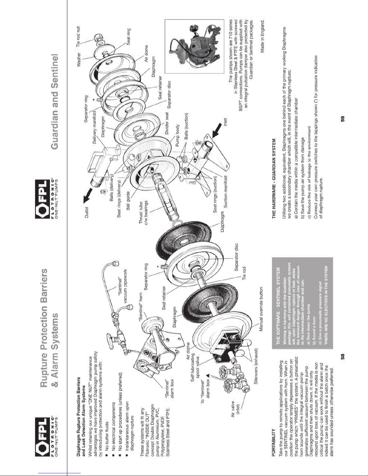
Page 62
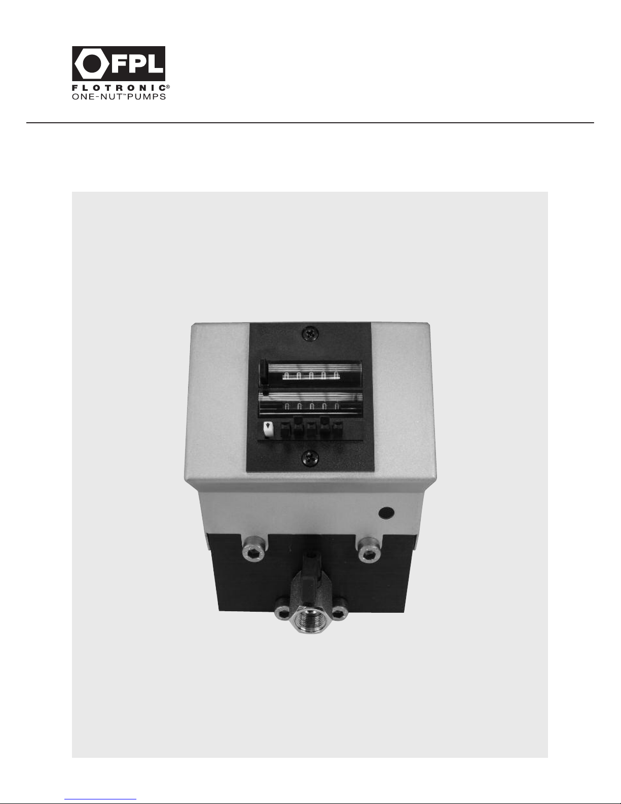
60
Count & Stop Pumps
All Series
Section 19 - Count & Stop Pumps - All Series
Page 63
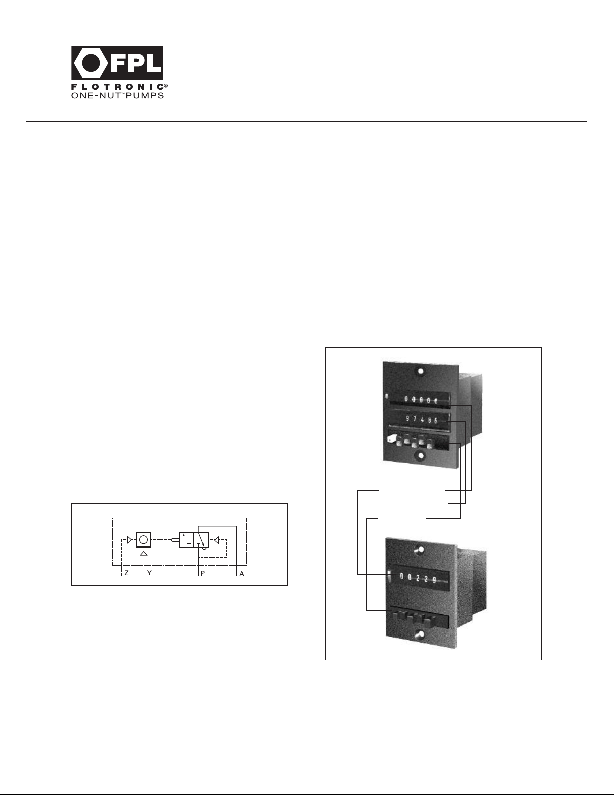
Applications
Pneumatic preset counters are used for
controlling and monitoring operating sequences
capable of being expressed as numbers in
pneumatic circuits, systems or equipment.
After the counter has counted the preset number
of pneumatic pulses, which can represent a
number of items or a number of operating
cycles, it emits a pneumatic output signal which
is used to start the next following process or
operation. The preset value can be selected
anywhere between 1 and 99999.
Connections
Pre-assembled at the Flotronic factory prior to
despatch.
Z input for count pulse
Y input for reset pulse
P air input
A output signal (set time has elapsed)
Operation
Each digit of the preset count figure can be set
independently.
Setting of adding predetermining counters
Push white lever as shown by the arrow and hold
it. Set the desired figures with the corresponding
keys. Release white lever.
61
Count & Stop Pumps
All Series
Section 19 - Count & Stop Pumps - All Series
All FPL pumps can be fitted with Count and Stop devices, which are normally mounted into a control
panel attached to the air valve assembly.
The counter used is of proprietary manufacture.
FPL reserve the right to provide alternative types of Count and Stop Devices of similar but not necessarily
the same operation.
Units can be remote mounted if required contact FPL for maximum remote connections.
actual value
pre-set value
Pre-set
pushbuttons
Setting of subtracting predetermining counters
Press reset button and at the same time enter the
desired preset figure by means of the preset keys.
INDICATION
Medium: Filtered compressed air, with no oil.
Working pressure: 2 to 8 bar.
Page 64

62
Trouble Shooting
Section 20 - Trouble Shooting
This section covers the most common “problems” associated with Flotronic Air Driven Double
Diaphragm Pumps. Naturally, all events cannot be covered and you should telephone the Technical
Support Office on 01444 881871 for further assistance.
Q=Question?
A=Answer.
Q Diaphragms fail after very short working life?
A Silencers may be blocked. Check and replace.
Did you wait 5 minutes when you installed the diaphragms to ensure that the PTFE had time to
“settle - cold flow” before retightening. If not, an adequate seal would not have been made
between the base of the diaphragm and the thrust tube. See diagram fitting procedures.
Q Pump stalls?
A Check that the air supply line to the pump is of the same internal diameter as the on - off air valve
supplied with the pump. Ensure that this supply line is as short as possible, coils of pipe restrict
air volume.
Ensure that any solenoid control is located next to the pump, not further than 1 metre away,
otherwise when the solenoid turns off the air supply, the air left in the line will “die down” and
could stall out the pump. Ensure both silencers are fitted. The pump needs the back pressure
provided by the silencers to ensure the anti-stall system works correctly.
Q Pump doesn’t suck?
A Replace Divider Seal.
Ensure suction connection pipework is adequately sealed to pump fitting. If there is a tiny leak, the
pump will pull air through instead of lifting the liquid to be pumped.
Q Pump won’t cycle?
A The ‘Head’ of liquid may be equal to the air supply pressure available. Either relieve head pressure
or increase air pressure (within normal 7 bar G max limit).
Q Pump only works one cycle?
A The tie-rod and thrust tube are installed incorrectly. You must ensure that the bearings inside the
thrust tube are at the air valve end of the pump, once the tie rod is fitted. Either remove the tie rod
now and insert it on the other side of the pump or, if this is not possible due to air supply pipework,
remove the thrust tube and diaphragms and turn the thrust tube around to the correct position, as
shown in Section 10.
Q Pump cycles when pump is stalled against a closed head?
A This is normal with Flotronic and assists the anti-stall mechanism of the pump. It is normal for the
pump to cycle once or twice a minute, but if it cycles more, replace the divider seal.
Page 65
63
Your Notes
Page 66

64
DON’T
Further Assistance
Follow these few tips to achieve best results from your Flotronic Pump
DO
Use only genuine FPL spare parts
Tighten nut up in accordance with
torque figures provided in Section 8
Use flexible air pipe to avoid side loads
Change divider seal regularly
Keep diaphragms on the “keeper” and
inside the box supplied until required
Change silencers regularly
Change diaphragms in pairs not singly
Filter air supply
Restrict air supply/volume with
adapters or coils of pipe
Attempt to alter, modify or reconstruct
the pump in any way whatsoever
as this will invalidate any warranty
In the event of a diaphragm failure
do not leave chemicals in the pump
as this can cause internal corrosion
Run the pump with a closed
or restricted suction valve
Operate pump without first ensuring
fastenings are correctly tightened,
see Section 8 for Torque Figures
Start pump if ice could be present
in the wetted chambers
Run pump without silencers fitted
Lubricate air valve
Leave PTFE Diaphragm 5 minutes to settle
once fitted before retightening them again.
Pull air spool cylinder out of perforated tube on
pumps with 7” and 10” diameter diaphragms,
it won’t go back in!
The information that is given in this manual is given in good faith and is accurate at the time of going to press. Flotronic reserve the
right to modify and change any of our products, without notice, in accordance with our policy for continued product improvement
through research and development.
Page 67
65
Your Notes
Page 68
66
Your Notes
Page 69

67
Further Assistance
Section 21 - Further Assistance
Remember!
If you require any further assistance, please call us on our
Helpline Number 01444 881871
or Email us at [email protected]
Viton®is a registered trademark of DuPont Dow Elastomers
Hastelloy®is a registered trademark of Haynes International
Flotronic Pumps Limited also provide:
• Planned maintenance programmes to suit your needs
carried out by one of our Specialist Engineers
• Pulsation Dampers
• Alarm Systems
• Jacketed Pumps
• Metering Systems
And much more...
Customised products are a speciality.
Page 70

Flotronic Pumps Limited.
Ricebridge Works, Brighton Road, Bolney, West Sussex RH17 5NA. UK
Tel: +44 (0)1444 881871 Fax: +44 (0)1444 881860
Email: [email protected] Web: www.flotronicpumps.co.uk
For authentic pump spares go to: www.flotronicspares.co.uk
Hastelloy®is a registered trademark of Haynes International.
‘Flotronic’ is a UK registered trade mark.
Specifications subject to change without notice.
IOM UK October 2016 RevG
 Loading...