

Page 1
IOM-DM MPT100-2018
Page 1
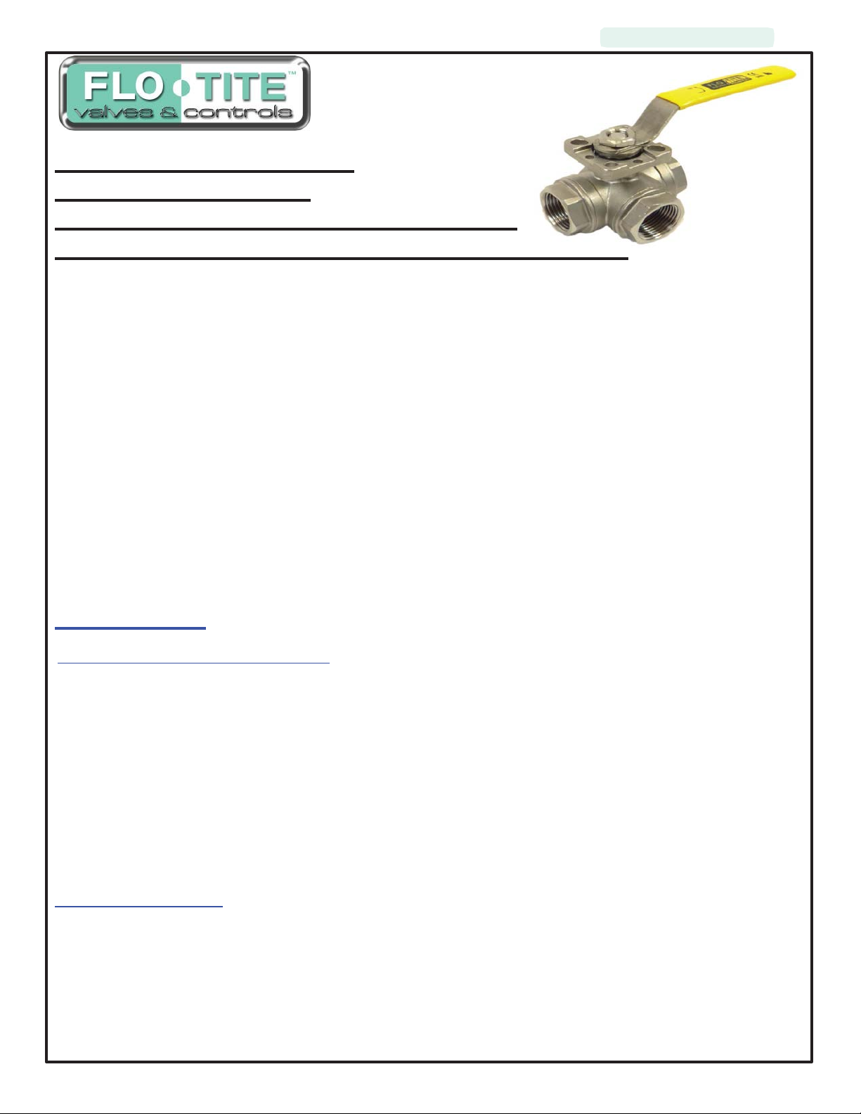
Flo-Tite Multi-Port Series
Model DM MPT100SS
Standard Port Threaded End 800 WOG
Installation, Operation and Maintenance Manual
Note:
Before
using a
valve,
read the entire IOM
carefully
and make sure you have a clear understanding of all
information included.
This
manual describes the procedures for the
Flo-Tite Multi Port
warranties
being voided. Problems with the operation and maintenance of these
Series Ball
Valves.
Failure
safe
and
efficient
to follow the
installation, operation, and maintenance of
procedures
in this manual may result in Flo-Tite
valves
should be
directed to
the nearest Flo-Tite Representative.
The Flo-Tite DM MPT100SS is designed as a split body, two-piece construction, to
maintenance of the
principle. The ball is not
tight shut-off with the
The downstream seat, which is opposite the pressurized side, of a closed
valve
ball and seat without special tools. This line of
fixed
but is free to move with the line pressure. As a result, these
flow
in either direction or dead-ended, regardless of the position of the
valves
valve,
utilizes the
must carry the load exerted by
the line pressure on the ball, while the upstream seat is subject to little load or wear. For this reason,
sometimes possible to increase useful seat
INSTALLATION:
A. Receiving and Preparation Procedure
life
by turning the
valve
end-for-end in the pipeline.
A1. Remove shipping protection
A2. Inspect the valve(s) for transportation damage*
A3. Inspect the valve bore and remove any debris
A4. Cycle the valve and inspect the valve for smooth operation, size permitting
A5. As shipped from the factory, valves may contain a silicone based lubricant. This is for break-in and may
be removed if it is objectionable for a particular application by disassembling and solvent washing.
allow
ease of
“free-floating”
valves
valve
access fo
ball
are capable of
in the line.
it is
*If transportation damage is found, immediately take pictures for record purposes and contact the inbound
carrier to submit a claim.
B. Installation Procedure
B1. General – The valve may be fitted in any position in the pipeline. Prior to installing the valve, the pipe
on either side of the intended installation should be checked to be free of dirt, debris, weld slag, etc. to prevent
damage to the seats, seals, and surface of the ball. The piping must also be free of tension or compression.
WARNING – Never use the valve as a pipe support or structural member.
r
Page 2

IOM-DM MPT100-2018
Page 2
B2. Installation of the Flo-Tite Multi-Port DM MPT100 valve is accomplished by inserting the valve between
flanges attached to piping and supplied by others and attaching the valve to the mating flanges with fasteners
of the size and type specified by industry standards. Fasteners should be tightened in a “star” pattern.
Caution – Ensure that mating flanges are of the same size, type and pressure rating as the valve and that
fasteners are of the size and type approved for the flange.
B3. Valves with actuators should be checked for actuator-valve alignment. Angular or linear misalignment
will result in high operational torque. Electric and/or pneumatic connections should be made in accordance
with the correct actuator IOM instructions.
C. OPERATION:
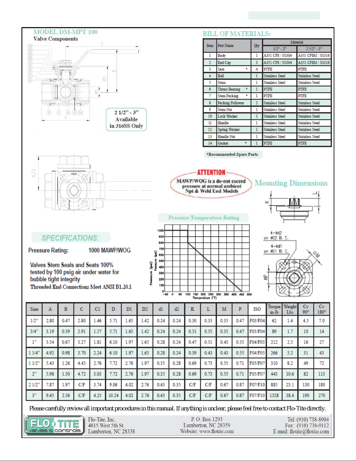
C1. Valve Flow Path is indicated by markings on the top of ball valve stem. The illustration on th e last page
shows standard valve position at the time of shipmen t.
C2. Flo-Tite model DM MPT100 valves can be operated with either electric or pneumatic actuators. For
instructions on installation and operation, refer to the IOM for the correct actuator. Prior to actuator
installation, please check the flow path of the valve as indicated by marking on the top of ball valve stem as
shown in the illustrations on th e last page. A fter actuator in stallation, the valve should be check for valve stem
alignment. Axial misalignment will result in high operational torque and unnecessary wear on the stem seal.
C3. Flo-Tite model DM MPT100 valves may include one of several different styles of limit switches and
positioners. Please refer to the appropriate IOM for each device.
MAINTENANCE:
CAUTION – Ball valves can trap fluid in the ba ll cavity when closed. Be prepared to capture and man age
any liquid retained in the valve body when disassembling the valve.
WARNING – If the valve has been in hazardous fluid service, review applicable MSDS sheet and
decontaminate the valve before disassembly. All persons involved with the disassembly should wear
personal protective equipment such as aprons, gloves, face shield, etc. to prevent personal injury.
Access to the valve internals starts with relieving pressure in the pipeline. Turn the valve handle to the 45
degree, half open, position and flush the line, when applicable, to remove any hazardous material from the
line. Consult the metal tag attached to the valve body to determine the correct s eat an d seal m ateria ls. Rep air
kits can be ordered from the local Flo-Tite Representative. This should be done prior to any disassembly
work.
CAUTION - V alves with actuators, limit switches or position ers should have these devices disassemb led from
the valve prior to disassembling of the valve.
WARNING-
Use extreme caution disconnecting any electrical and/or pneumatic sources to the valve to protect
against personal injury. Isolate the valve actuator prior to disconnecting.
Stem Packing
Stem seal leakage may be corrected without disassembly. Tighten the packing gland nuts one flat at a time
alternating between nuts, until leakage stops. If l eakage continues, or the v alve’s operating torque b ecomes
excessive, the seals are worn and replacement of the packing will be necessary.
Page 3

IOM-DM MPT100-2018
Page 3
WARNING-
Do not remove packing gland while the line is under pressure. Personal injury could occur.
D. Valve Disassembly-
WARNING
Use extreme caution when removing the flanged valve from the pipeline to prevent personal injury
that may be caused by “cold springing” of the piping.
CAUTION
Valves shall be adequately supported prior to unfastening the studs and nuts that hold the valve in line and
secured with lifting straps or slings to hold the weight of the valve.
D1. Remove the threaded end caps and lift the valve from the line for s erv ice . N ote – care should be taken to
avoid scratching or damaging the threaded end caps. Damaged gaskets must be replaced prior to
Reinstalling in the line.
D2. Loosen handle nut and remove handle. Remove spring washer as well.
D3. Mark each threaded end cap to the body joint. This is to allow ease of alignment in re-installation.
D4. Safely place the valve on a clean, secure and stable work surface.
D5. Protect the end caps when handling to prevent scratching and damage.
D6. EXTREME CARE should be taken upon ball removal as not to scratch seating surface or the
stem, which will result in leakage after reassembly.
D7. Remove Seats and Gaskets. Use caution to prevent damage to metal parts.
D8. Remove lock washer, stem nut, packing follower, stem packing & thrust bearing.
D9. Take ball & stem out of valve body, remove Stem Bushing.
CAUTION
Use extreme care in handling the ball to avoid damage. The stem must be removed from the inside of the body.
Gently tap the top of the stem with a non-metallic mallet. The thrust washer should come out with the stem.
Stem packing can now be removed. If a packing pick is used to remove packing, care must be taken not to
scratch any surface.
Visual Inspection-
Clean and inspect all metal parts. It is not necessary to replace the ball and stem unless the seating surfaces
have been damaged by abrasion or corrosion. Flo-Tite strongly recommends that all seats, seals, and packing
be replaced whenever a valve is disassembled for reconditioning. This is the surest protection against
subsequent leakage after reassembly. Replacement parts are sold in kit form. Refer to the metal tag
attached to the side of the valve body to identify the specific sealing materials used. Kits can be obtained via
the local Flo-Tite Distributor. Replacement parts should be purchased prior to valve disassembly. Required
information to purchase replacement parts include:
a. Line size
b. Model designation
c. Seat/seal materials – see stamping on metal tag
attached to the valve body.
Page 4

IOM-DM MPT100-2018
Page 4
Valve Reassembly -
Note- the valve may be reassembled and operated dry when no lubricants are allowed in the system;
however, a light lubricant on the ball and stem will aid in assembly or reduce initial operating torque.
Lubricant used must be compatible with the intended system fluid.
1. Install the thrust bearing on stem O.D.
2. Install stem packing in valve body.
3. Slide the Ball & Stem into the stem bushing.
4. Install the seats inside each seat pocket of the end caps make sure the spherical curvature side of the
seat will face the ball.
10. Turn the ball so that the ball opening is parallel to the port centerline.
11. Assemble the end cap onto the valve body, loosely tighten End Cap Nuts. Place remaining seats to
correct end caps and gradually tighten all three end caps in rotation, using a crisscross pattern on each
end. Do not fully tighten one end cap, bring them all up gradually.
NOTE:
Be careful not to damage gasket when putting end cap into the body.
12. Tighten packing gland, ensure valve operates smoothly
Note:
Valve must be in the 100% full open position.
13. Install, lock washer, stem nut, packing follower, stem packing & thrust bearing.
14. Install Lever.
Note:
Make sure ball is in closed position before tightening up the end connections.
WARNING
Extreme care must be exercised during tightening of the body end nuts to make sure that complete
engagement of studs with the body flange is maintained. There should be at least one stud thread
exposed on each side.
Cycle the valve slowly, with a gentle back and forth motion to build gradually to a full quarter turn. By
cycling slowly, the new seat lips will conform to the seal shape against the ball. An initial fast turning
motion, at this point, may cut the seats before they have a chance to form the proper seal. When possible
and practical, test the valve prior to reinstalling into the pipeline.
Reinstallation-
Carefully inspect the faces of both the valve flanges and the mating flanges to ensure they are clean and
undamaged. Place the valve in the preferred position and support it from moving. Install a sealing gasket
between each pair of flanges and reinsert the bolting and hand tighten. Secure the bolting to the
recommended torque values in a star pattern to ensure that the gasket is compressed evenly around the entire
circumference.
Page 5
IOM-DM MPT100-2018
Page 5
Valve Size
VALVE - SOFT PARTS
SEAT STEM SEALS BODY SEAL O-RINGS
TFM F TFM F TFM
F
VITON
V
CTFM
Y CTFM
Y CTFM
Y EPDM E
PTFE
T RTFM
X PTFE
T PTFE T
RPTFE
R PTFE
T RPTFE
R BUNA B
50/50
S RPTFE
R 50/50
S NONE
N
UHMWPE
U 50/50
S UHMWPE
U
PEEK
P
UHMWPE
U PEEK
P
Cavity
Filled
C PEEK
P
Graphite
G
Metal
M
Graphite
G Kel-F
K
Kel-F
K
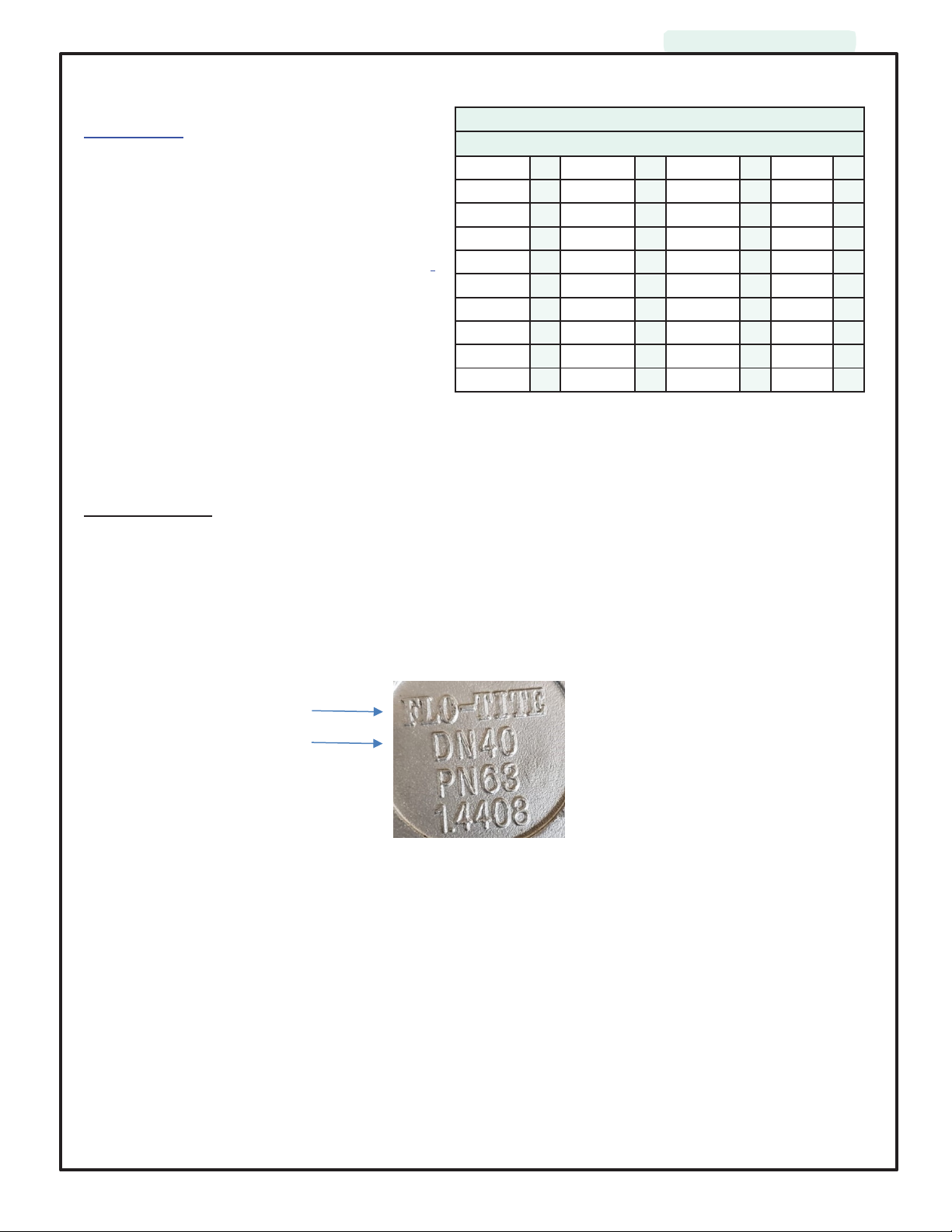
Repair Kits –
Repair kits typically consist of replaceable
seats, body seals, and packing seals. Refer to
the unit nameplate, as shown below, to confirm
what materials are currently installed. Contact
your local Flo-Tite Representative to order and
receive the kits prior to any maintenance work.
F lo-Tite’s marking system follows MSS SP-25-1998
Valve Markings- Casted into valve bodies include the following; Flo-Tite Name, Model Numbers, Body
Material, Valve Size, & WOG Pressure Rating
All Flo-Tite valves have metal name plates spot welded to the valve
body.
Standard Trim Soft
Parts
Flo-Tite Name
Valve Side A
Page 6
IOM-DM MPT100-2018
Page 6
Please carefully review all important procedures in this manual. If anything is unclear, please feel free to contact Flo-Tite directly.
Page 7

IOM-DM MPT100-2018
Page 7
Page 8

IOM-DM MPT100-2018
Page 8
 Loading...