

Flotec Multi-Stage Pump, FP4432-01 Owner's Manual
Installation/Operation/Parts
For further operating, installation,
or maintenance assistance:
Call 1-800-365-6832
English . . . . . . . . . . . . . . Pages 2-13
Installation/Fonctionnement/Pièces
Pour plus de renseignements
concernant l’utilisation,
l’installation ou l’entretien,
Composer le
1 (800) 365-6832
Français . . . . . . . . . . . Pages 14-25
Instalación/Operación/Piezas
Para mayor información sobre el
funcionamiento, instalación o
mantenimiento de la bomba:
Llame al 1-800-365-6832
Español . . . . . . . . . . .Paginas 26-37
©2005 S183 (Rev. 7/13/05)
P.O. Box 342, Delavan, WI 53115
Phone:
1-800-365-6832
Fax:
1-800-526-3757
E-Mail:
info@flotecwater.com
Web Site:
http://www.flotecwater.com
OWNER’S MANUAL
Multi-Stage Pump
NOTICE D’UTILISATION
Pompe multiprofondeur
MANUAL DEL USUARIO
Bomba Multietapas
®

Table of Contents 2
Thank you for purchasing a top quality, factory tested pump.
Page
Warranty..............................................................................................................2
General Safety .....................................................................................................3
Performance.........................................................................................................4
Installation........................................................................................................5-8
Electrical.........................................................................................................8-10
Operation...........................................................................................................11
Repair Parts........................................................................................................12
Troubleshooting .................................................................................................13
For parts or assistance, call Flotec Customer Service at 1-800-365-6832
ATTACH ORIGINAL RECEIPT HERE FOR WARRANTY CONSIDERATION.
FLOTEC warrants to the original consumer purchaser (“Purchaser”) of its products that they are free from defects in material or workmanship.
If within twelve (12) months from the date of the original consumer purchase
any such product shall prove to be defective, it shall be repaired or replaced at
FLOTEC’s option, subject to the terms and conditions set forth below. Your original receipt of purchase is required to determine warranty eligibility.
Exceptions to the Twelve (12) Month Warranty
Ninety (90) Day Warranty:
If within ninety (90) days from original consumer purchase any Drill Pump,
Pitcher Pump, or In-Line Water Filter Cartridge shall prove to be defective, it
shall be replaced, subject to the terms set forth below.
Two (2) Year Warranty:
If within two (2) years from original consumer purchase any 1/3 HP Submersible
Sump Pump or Model FP2800DCC shall prove to be defective, it shall be
repaired or replaced at FLOTEC’s option, subject to the terms and conditions set
forth below.
Three (3) Year Warranty:
If within three (3) years from original consumer purchase any 4” Submersible
Well Pump, or 1/2 HP Submersible Sump Pump, shall prove to be defective, it
shall be repaired or replaced at FLOTEC’s option, subject to the terms and conditions set forth below.
Four (4) Year Warranty:
If within four (4) years from original consumer purchase any FLOODMATE
TM
7000 or IRONMATETMSubmersible Sump Pump shall prove to be defective, it
shall be repaired or replaced at FLOTEC’s option, subject to the terms and conditions set forth below.
Five (5) Year Warranty:
If within five (5) years from original consumer purchase any Pre-Charge water
system tank shall prove to be defective, it shall be repaired or replaced at
FLOTEC’s option, subject to the terms and conditions set forth below.
General Terms and Conditions
Purchaser must pay all labor and shipping charges necessary to replace product
covered by this warranty. This warranty shall not apply to acts of God, nor shall
it apply to products which, in the sole judgement of FLOTEC, have been subject
to negligence, abuse, accident, misapplication, tampering, alteration; nor due to
improper installation, operation, maintenance or storage; nor to other than normal application, use or service, including but not limited to, operational failures
caused by corrosion, rust or other foreign materials in the system, or operation
at pressures in excess of recommended maximums.
Requests for service under this warranty shall be made by returning the defective
product to the Retail outlet or to FLOTEC as soon as possible after the discovery
of any alleged defect. FLOTEC will subsequently take corrective action as
promptly as reasonably possible. No requests for service under this warranty will
be accepted if received more than 30 days after the term of the warranty.
This warranty sets forth FLOTEC’s sole obligation and purchaser’s exclusive
remedy for defective products.
FLOTEC SHALL NOT BE LIABLE FOR ANY CONSEQUENTIAL, INCIDENTAL,
OR CONTINGENT DAMAGES WHATSOEVER.
THE FOREGOING WARRANTIES ARE EXCLUSIVE AND IN LIEU OF ALL
OTHER EXPRESS WARRANTIES. IMPLIED WARRANTIES, INCLUDING BUT
NOT LIMITED TO THE IMPLIED WARRANTIES OF MERCHANTABILITY AND
FITNESS FOR A PARTICULAR PURPOSE, SHALL NOT EXTEND BEYOND THE
DURATION OF THE APPLICABLE EXPRESS WARRANTIES PROVIDED HEREIN.
Some states do not allow the exclusion or limitation of incidental or consequential damages or limitations on how long an implied warranty lasts, so the
above limitations or exclusions may not apply to you. This warranty gives you
specific legal rights and you may also have other rights which vary from state
to state.
Flotec Limited Warranty
FLOTEC • P.O. Box 342 • Delavan, WI U.S.A. 53115
Phone: 1-800-365-6832 • Fax: 1-800-526-3757
E-Mail: info@flotecwater.com • Web Site: http://www.flotecwater.com

Safety 3
For parts or assistance, call Flotec Customer Service at 1-800-365-6832
READ AND FOLLOW
SAFETY INSTRUCTIONS!
This is the safety alert symbol. When you see this
symbol on your pump or in this manual, look for
one of the following signal words and be alert to the
potential for personal injury!
DANGER warns about hazards that will
cause serious personal injury, death or major property
damage if ignored.
WARNING warns about hazards that can
cause serious personal injury, death or major property
damage if ignored.
CAUTION warns about hazards that will or
can cause minor personal injury or property damage if
ignored.
The word NOTICE indicates special instructions which
are important but not related to hazards.
Carefully read and follow all safety instructions in this
manual and on pump.
Keep safety labels in good condition.
Replace missing or damaged safety labels.
ELECTRICAL SAFETY
Wire motor for correct
voltage. See “Electrical”
section of this manual and
motor nameplate.
Ground motor before
connecting to power
supply.
Meet National Electrical
Code, Canadian
Electrical Code, and local
codes for all wiring.
Follow wiring instruc-
tions in this manual
when connecting motor to
power lines.
Make workshops childproof; use padlocks and master
switches; remove starter keys.
Capacitor voltage may be hazardous. To
discharge motor capacitor, hold insulated handle screwdriver BY THE HANDLE and short capacitor terminals
together. Do not touch metal screwdriver blade or capacitor terminals. If in doubt, consult a qualified electrician.
GENERAL INFORMATION
Do not allow pump or any system component to freeze.
To do so will void warranty.
Pump water only with this pump.
Periodically inspect pump and system components.
Wear safety glasses at all times when working on pumps.
Keep work area clean, uncluttered and properly lighted;
store properly all unused tools and equipment.
Keep visitors at a safe distance from the work areas.
To avoid over pressure hazard and possible injury, install
pressure relief valve capable of passing full pump flow at
75 PSI (517kPa). Pressurized suction may cause pump
body to explode.
Do not touch an operating motor. Modern
motors are designed to operate at high temperatures. To
avoid burns when servicing pump, allow it to cool for 20
minutes after shut-down before handling.
WARNING
Hazardous voltage. Can
shock, burn, or cause
death.
Ground pump before connecting to power supply.
Disconnect power before
working on pump, motor or
tank.
WARNING
Hazardous pressure!
Install pressure relief
valve in discharge pipe.
Release all pressure on
system before working on any
component.

Performance 4
For parts or assistance, call Flotec Customer Service at 1-800-365-6832
TABLE II – 4” Double Pipe Deep Well Installation Jet Selection Chart
JET
PIPE SIZES
H.P. NO.
SUCT. PRESS
J32P-24
Venturi
1
1-1/4” 1”
#52
Nozzle
J32P-18
Venturi
1
1-1/4” 1”
#52
Nozzle
DISCH
DEPTH TO WATER – FT (M) PERFORMANCE IN GPH (LPH)
PRESS
30 40 50 60 70 80 90 100 110 120 130 140 180 200 220 240 260
PSI(kPa) (9) (12) (15) (18) (21) (24) (27) (30) (33) (36) (40) (43) (55) (61) (67) (73) (79)
20 730 730 730 730 690 580 510 400 320 250 190 — — — — —
(138) (2763) (2763) (2763) (2763) (2612) (2195) (1930) (1514) (1211) (946) (719)
30 730 710 700 695 635 570 475 395 315 250 190 — — — — — —
(207) (2763) (2687) (2650) (2631) (2403) (2157) (1798) (1495) (1192) (946) (719)
40 725 700 695 665 610 550 465 385 300 240 180 — — — — — —
(275) (2744) (2650) (2631) (2517) (2309) (2082) (1760) (1457) (1136) (908) (681)
50 720 690 660 625 575 525 445 365 275 210 165 — — — — — —
(344) (2725) (2612) (2498) (2366) (2176) (1987) (1684) (1382) (1041) (795) (625)
60 700 660 615 570 520 470 400 325 230 180 140 — — — — — —
(413) (2650) (2498) (2328) (2157) (1968) (1779) (1514) (1230) (871) (681) (530)
20 330 330 330 330 330 320 310 305 305 300 290 270 230 190 150 115 80
(138) (1249) (1249) (1249) (1249) (1249) (1211) (1173) (1154) (1154) (1136) (1098) (1022) (871) (719) (568) (435) (303)
30 330 330 330 330 330 320 310 305 305 300 290 270 215 175 135 100 70
(207) (1249) (1249) (1249) (1249) (1249) (1211) (1173) (1154) (1154) (1136) (1098) (1022) (814) (662) (511) (379) (265)
40 330 330 330 325 320 315 310 305 305 300 290 270 195 160 120 80 60
(275) (1249) (1249) (1249) (1230) (1211) (1192) (1173) (1154) (1154) (1136) (1098) (1022) (738) (606) (454) (303) (227)
50 330 330 325 320 315 310 305 305 300 295 280 270 175 140 100 70 50
(344) (1249) (1249) (1230) (1211) (1192) (1173) (1154) (1154) (1136) (1117) (1060) (1022) (662) (530) (379) (265) (189)
60 325 325 320 315 310 305 300 295 285 280 270 255 155 125 85 60 40
(413) (1230) (1230) (1211) (1192) (1173) (1154) (1136) (1117) (1079) (1060) (1022) (965) (587) (473) (322) (227) (151)
JET
PIPE SIZES
DISCH
DEPTH TO WATER – FT (M) PERFORMANCE IN GPH (LPH)
PRESS
H.P. NO.
SUCT. PRESS
PSI(kPa)
30 40 50 60 70 80 90 100 110 120 130 140 180
(9) (12) (15) (18) (21) (24) (27) (30) (33) (36) (40) (43) (55)
J32P-24
20 730 710 705 660 600 480 430 350 210 110 — — —
Venturi (138) (2763) (2687) (2668) (2498) (2271) (1817) (1628) (1325) (795) (416)
30 730 690 675 630 555 470 400 345 205 110 — — —
(207) (2763) (2612) (2555) (2385) (2101) (1779) (1514) (1306) (776) (416)
1 1-1/4” 1 40 730 680 670 600 530 455 390 335 195 105 — — —
(275) (2763) (2574) (2536) (2271) (2006) (1722) (1476) (1268) (738) (397)
#52
50 725 670 640 565 500 435 375 320 180 90 — — —
Nozzle
(344) (2744) (2536) (2422) (2139) (1893) (1646) (1419) (1211) (681) (341)
60 700 640 595 515 450 390 335 285 150 80 — — —
(413) (2650) (2422) (2252) (1949) (1703) (1476) (1268) (1079) (568) (303)
20 330 330 320 320 320 310 300 300 300 300 270 250 140
J32P-18
(138) (1249) (1249) (1211) (1211) (1211) (1173) (1136) (1136) (1136) (1136) (1022) (946) (530)
Venturi
30 330 330 320 320 320 310 300 300 300 300 270 250 130
(207) (1249) (1249) (1211) (1211) (1211) (1173) (1136) (1136) (1136) (1136) (1022) (946) (492)
1 1-1/4” 1” 40 330 330 320 315 310 305 300 300 300 300 270 250 120
(275) (1249) (1249) (1211) (1192) (1173) (1154) (1136) (1136) (1136) (1136) (1022) (946) (454)
#52
50 330 330 315 310 305 300 300 300 300 295 260 250 105
Nozzle
(344) (1249) (1249) (1192) (1173) (1154) (1136) (1136) (1136) (1136) (1117) (984) (946) (397)
60 325 325 310 305 300 295 290 290 290 280 250 235 95
(413) (1230) (1230) (1173) (1154) (1136) (1117) (1098) (1098) (1098) (1060) (946) (889) (360)
Installation 5
PRE-INSTALLATION
1. A pump cannot pump air.
2. Long runs and many fittings increase friction and
reduce flow. Locate pump as close to well as possible. Keep pipe straight and angled up to pump. Use
as few elbows and fittings as possible. Support weight
of pipe.
3. Be sure well is clear of sand, dirt and scale which
will plug pump and void warranty.
4. Protect pump and piping from freezing. Freezing will
split pipe, damage pump and void warranty. Check
locally for frost protection requirements (usually pipe
must be 12" (30.5 cm) below frost line and pump
must be insulated).
5. Be sure pipes and foot valve are clean and in good
shape. Leaking foot valve due to dirt or scale may
allow pump to lose prime and cause pump failure.
6. No air pockets in suction pipe.
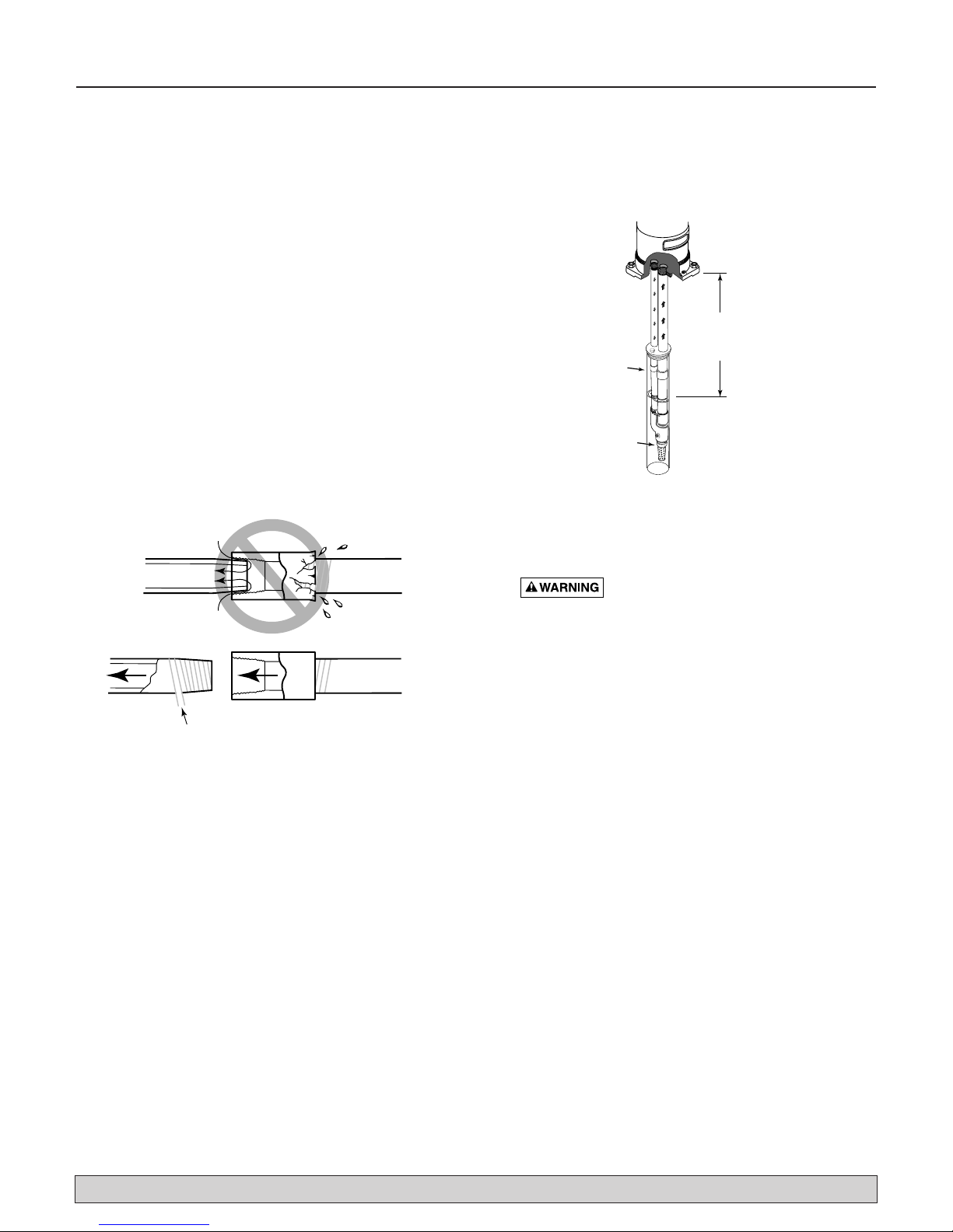
7. No air leaks in suction pipe. Use Teflon tape or
Plasto-Joint Stik to seal pipe joints. Do not use pipe
joint compound. (Figure 1).
NOTICE: A leak in suction may not drip (allows air to
be drawn in). Jet pumps will not pump air or prime
until all joints are sealed properly.
8. Match pump to well. Deep well is 25' (7.6M) or more
to water with pump running. (Figure 2)
NOTICE: Flow in to well must at least equal flow out
through pump! See Performance Chart.
9. Unions installed near pump and well will aid in servicing. Leave room to use wrenches.
10. Pump body may explode if used as
booster pump unless relief valve capable of passing
full pump flow at 75PSI (517kPa) is installed.
11. Be sure to prime pump before starting. Water acts as
lubricant. Starting without water will cause internal
damage and void warranty.
For parts or assistance, call Flotec Customer Service at 1-800-365-6832
Figure 1 – Suction pipe must not leak
Figure 2 – Match pump to well
g
w
(
w
n
Pipe Joint
No Air Leaks
in Suction Pipe.
If Air Flows
Water Won’t
Compound Will
Damage Plastic.
1" NPT
Plug
Shallow
than 25'
to water
pump ru
Foot
Valve &
Strainer
Well
Casin
Well
Casing
Foot
Valve &
Strainer
Deep well is more
than 25' (7.6M)
to water with
pump running.
Use Teflon Tape.
1102 0697

Installation 6
For parts or assistance, call Flotec Customer Service at 1-800-365-6832
DEEP WELL / DOUBLE PIPE
PIPING IN THE DEEP WELL (Figures 3 & 4)
NOTICE: Deep well installations are either single pipe
(2” wells) or double pipe (4” and larger wells). In a double pipe installation, the larger pipe is the suction pipe
and the smaller pipe is the drive pipe (very deep wells
may use suction and drive pipes of the same diameter).
Suction pipe always aligns with center of pump.
Plastic pipe is ideal for double pipe installations. Due to
its light weight, it is easy to handle and does not usually
require a block and tackle for installation and removal.
PLASTIC PIPE INSTALLATION –
DOUBLE PIPE (Figures 3 & 4)
NOTICE: Use Teflon tape on all male threads on plastic
pipe and fittings to prevent air leaks in suction piping.
1. Inspect jet to make sure that nozzle and venturi
openings are clean and clear.
2. Inspect pipe for any foreign matter or obstructions.
IMPORTANT: Make sure that no foreign matter enters
pipe openings while installing pump.
3. Make sure foot valve operates freely: attach to jet
with a close nipple. Use Teflon tape on male threads.
4. Install nozzle and venturi in deep well jet. Consult
Table II for proper nozzle and venturi.
5. Using Teflon tape on male threads, install special
plastic pipe adapter (supplied with jet package) by
screwing adapter into 1-1/4” tapped hole in ejector
body.
6. Thread a 1” plastic pipe adapter into the 1” tapped
hole in jet body.
7. Install sufficient plastic pipe in well casing to place
jet at the proper depth. (Your well driller should supply this information.)
IMPORTANT: As a guide, the jet should be set at least
10 to 20 ft. (3-6M) below lowest water level with
pump running, but always at least 5 ft. (1.5M) from
bottom of well.
8. Tighten hose clamps on plastic pipe. Use 2 clamps
per joint to prevent air leaks into suction pipe. Clamp
screws should be on opposite sides of pipe. Fill pipes
with water to make sure foot valve and connections
do not leak.
9. Install sanitary well seal on top of well casing; use
steel nipple through well seal.
IMPORTANT: Align locating lugs on adapter flange
and pump base so pump discharge will be aligned
with piping.
10.Install nipple in drive pipe side of adapter flange.
Slide threadless coupling down over drive pipe from
well. Thread adapter flange onto suction pipe from
well and align nipple and drive pipe.
11. Slide threadless coupling up and secure nipple to
drive pipe.
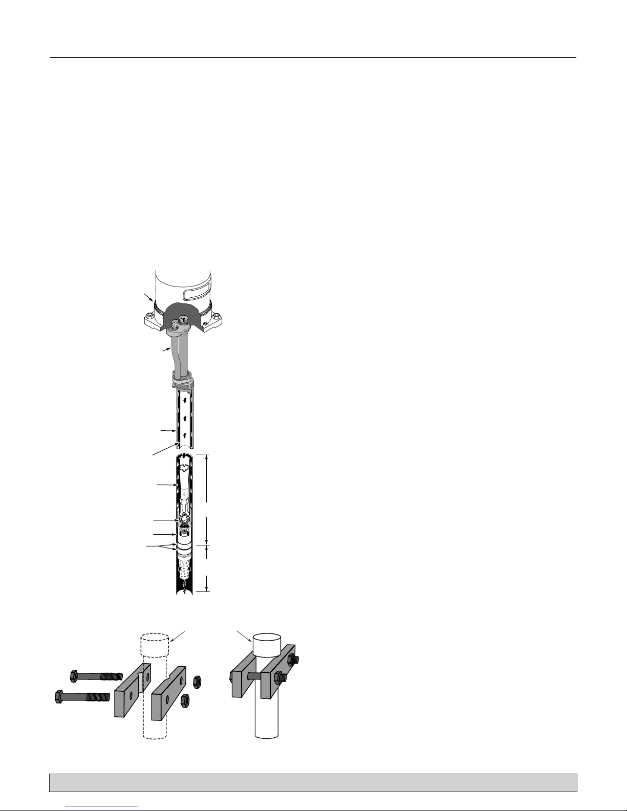
Figure 3 – Over the well installation
Figure 4 – Offset installation
Pump
Gasket
Adapter Flange
Threadless Coupling
Sanitary
Well Seal
1" Drive Pipe
1-1/4" Suction Pipe
Ejector Assembly
Foot Valve & Strainer
474 0194
Pump
Gasket
Adapter Flange
Sanitary
Well Seal
Steel Pipe Nipple
Coupling
1" Plastic Drive Pipe
1-1/4" Plastic Suction Pipe
Special 1-1/4" Plastic Pipe
Adapter. (Supplied with Ejector)
1" Plastic Pipe Adapter
Ejector Assembly
Foot Valve & Strainer
Threadless
Coupling
Installation 7
For parts or assistance, call Flotec Customer Service at 1-800-365-6832
12.Apply gasket to adapter flange. Be sure holes line up.
13.Align locating lugs on pump base with locating lugs
on adapter flange; attach pump to flange with cap
screws provided.
14.See “Discharge Pipe Sizes” for information regarding
correct discharge pipe size.
DEEP WELL / SINGLE PIPE
2" SINGLE PIPE JET DEEP WELL
INSTALLATION (Figures 5 and 6)
Single pipe installations require :
A. Galvanized steel pipe
B. Leather packer-type jet with built-in foot valve
C. Turned couplings (supplied with jet package)
D. Well casing adapter and adapter flange (supplied
with jet package)
E. Offset nipple (supplied with jet package)
F. Pipe holders (see Figure 6B)
1. Place jet in pail of water for two or more hours to
soak cup seals. See Table III for proper venturi and
nozzle.
2. After cup seals are thoroughly soaked, connect jet to
first length of pipe. Use pipe joint compound sparingly on male threads.
NOTICE: Due to normal irregularities in the leather of
the cup seals and the inner walls of the drop pipe, 2"
packer jets do not form a perfect seal. In a dormant
system, water will leak back into well over time and
pump will normally start and cycle to maintain system pressure level.
3. Lower pipe into casing. Use specially turned couplings (included with 2” single pipe jet package) to
increase water flow. Use pipe joint compound sparingly on male couplings threads.
NOTICE: Fill pipe with water as each length is added
to be sure foot valve and connections do not leak.
4. Add lengths of pipe until jet reaches proper depth.
(Contact your local well driller.)
IMPORTANT: As a guide, the jet should be set at least
10 to 20 ft. (3-6M) below lowest water level with
pump running, but always at least 5 ft. (1.5M) from
bottom of well.
5. With jet at the proper depth for your installation,
mark the drop pipe 6” above the top of the well casing, then raise the drop pipe about 18 inches and
clamp it there to allow room to install the casing
adapter, offset nipple, and adapter flange.
6. Cut off the drop pipe at the mark you made in Step 5.
Thread the top of the pipe 1” NPT to take the adapter
flange.
7. Slide the casing adapter over the top of the drop pipe
with bolts in place and leave it loose on the pipe.
8. Thread the drop pipe into the adapter flange; thread
the offset nipple into the adapter flange until it is tight
and aligns with its port inthe casing adapter.
9. Remove pipe holder and lower pipe assembly until
casing adapter seats on well head and offset nipple
seats in casing adapter port. Before tightening casing
adapter bolts, move assembly up and down slightly.
Water pressure in the casing will seal the cup seals.
10.Tighten casing adapter bolts to fasten the casing
adapter to the well casing.
11. Install gasket on adapter flange and bolt pump to
adapter flange.
IMPORTANT: Align locating lugs on adapter flange
and pump base so that pump discharge will be
aligned with piping.
Figure 5 – 2" Single pipe
Figure 6 – Pipeholder details
Pump
mounted
on Casing
Adapter
Offset Nipple
Well Casing
serves as
Drive Pipe
Suction
Pipe
Venturi
Nozzle
Ejector
Cup
Leathers
2357c 0797
Water level
with pump
running
24
J32P-
JET NO.
10 to 20 Feet
5 Feet
or more
Turned Coupling
1387 11
Installation / Electrical 8
For parts or assistance, call Flotec Customer Service at 1-800-365-6832
DISCHARGE PIPE SIZES
1. If increasing discharge pipe size, install reducer in
pump discharge port. Do not increase pipe size by
stages.
2. When pump is set away from the points of water use,
discharge pipe size should be increased to reduce
pressure losses caused by friction.
• Up to 100 ft (30M) run: Same size as pump discharge port.
• 100 ft. to 300 ft (30-91M) run: Increase one pipe
size.
• 300 ft. to 600 ft (91M-183M)run: Increase two
pipe sizes.
PRESSURE TANK INSTALLATION –
DEEP WELL
A pressure tank provides a reservoir of water under pressure and maintains a cushion of air pressure to prevent
pipe hammering and possible damage to plumbing components. When water is drawn off through house fixtures,
pressure in tank is lowered and pressure switch starts
pump.
STANDARD TANK CONNECTION (Figure 7)
With a standard tank - an air volume control (AVC) adds
air to the tank when needed.To connect AVC to pump,
thread a 1/8” compression fitting into tapped hole on
front of pump. Cut tubing to length to reach AVC; assemble to fitting on pump and to AVC on tank. See installation instructions provided with tank and AVC for details.
PRECHARGED TANK CONNECTION
(Figure 8)
No AVC is necessary with a precharged tank. A
precharged tank contains a factory provided air charge.
IMPORTANT: Pump pressure switch is set for a 40-60 PSI
(275-414kPa) range and requires a tank pre-charge of 38
PSI (262 kPa) for proper operation. See tank owner’s
manual for air charge. An annual check on tank air
charge is recommended.
ELECTRICAL
Ground motor before
connecting to electrical
power supply.
Failure to ground motor
can cause severe or fatal
electrical shock hazard.
Do not ground to a gas
supply line.
To avoid dangerous or
fatal electrical shock,
turn OFF power to motor
before working on electrical
connections.
Supply voltage must be
within ±10% of name-
plate voltage. Incorrect voltage can cause fire or seriously damage motor and voids warranty. If in doubt consult a licensed electrician.
Use wire size specified in Wiring Chart. If possible,
connect pump to a separate branch circuit with no
other appliances on it.
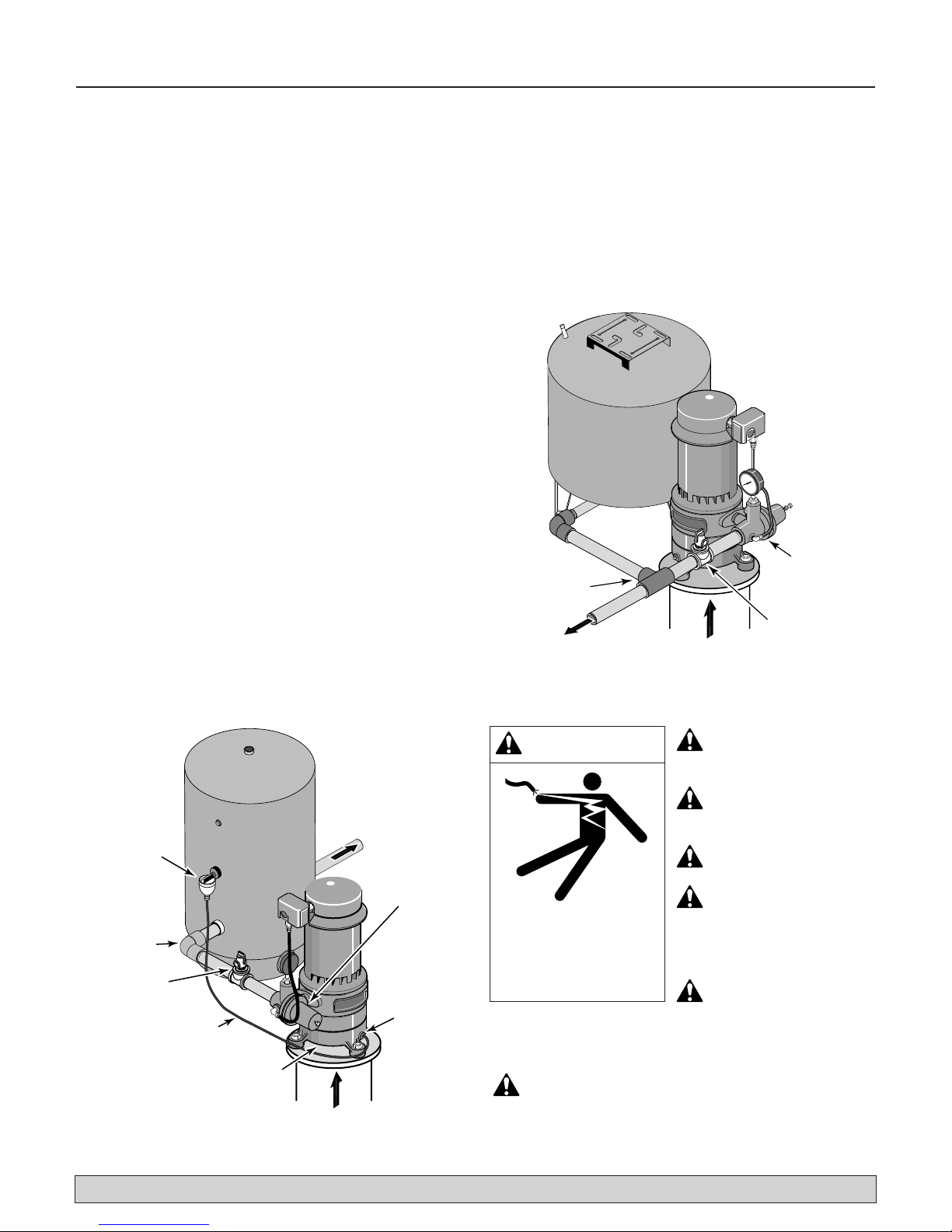
Figure 7 – Pump on standard tank - shallow well
Figure 8 – Pump with pre-charged tank
WARNING
Hazardous voltage. Can
shock, burn, or cause
death.
Ground pump before connecting to power supply
Pre-Charged
Pressure Tank
6
40
0
20
80
100
Pressure
1" Discharge
2358b 0697
Regulator
Relief Valve
Standard Tank
Air Volume
Control
(AVC)
1" Discharge
Relief Valve
AVC Tubing
Well Seal
2355b 0697
Pressure
Regulator
AVC
Port
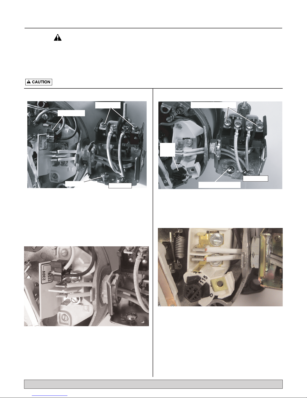
Electrical 9
For parts or assistance, call Flotec Customer Service at 1-800-365-6832
Plug Type Voltage Selector
Voltage is factory set to 230 volts. To change to 115 volts:
1. Make sure power is off.
2. Pull the voltage change plug off of the tabs.
3. Move the voltage change plug to the 115 volt position. The plug will now cover 2 metal tabs and the
arrow on the plug will line up with the 115V arrow on
the label (see Figure 10).
4. Attach the incoming power leads to the two outer
screws on the pressure switch as shown in Figure 9.
5. Attach the ground wire to one of the grounding
connections, shown in Figure 9.
6. If there are other wires, they should be capped.
7. Reinstall the Motor end cover.
Dial Type Voltage Selector
Voltage is factory set to 230 volts. To change to 115 volts:
1. Make sure power is off.
2. Turn the dial counter-clockwise until 115 shows in the
dial window as shown in Figure 12.
3. Attach the incoming power leads to the two outer
screws on the pressure switch as shown in Figure 11.
4. Attach the ground wire to the grounding connections
as shown in Figure 11.
5. If there are other wires, they should be capped.
6. Reinstall the Motor end cover.
NOTE: 1/2 HP motors are wired for 115 volts only, and have no motor wiring to change.
Your motor terminal board (located under the motor end cover) should look like one of those below.
If the motor can operate at either 115 or 230 volts, it is set at the factory to 230 volts. Do not change motor wiring if
line voltage is 230 volts, or if you have a single voltage motor.
Never wire a 115 volt motor to a 230 volt line.
Motor Switch Settings
Figure 9:Voltage set to 230 volts, Plug Type
Figure 10:Voltage set to 115 volts, Plug Type
Figure 11:Voltage set to 230 volts, Dial Type
Figure 12:Voltage set to 115 volts, Dial Type
Disconnect power before working on pump, motor, pressure switch, or wiring.
Power Connections
Voltage Change Plug
Ground Wire Connection
Pressure Switch
Power Supply Connections
Voltage
Change
Dial
Pressure Switch
Ground Wire Connection

Electrical 10
Wiring (Figure 9)
1. Install, ground, wire and maintain pump in accordance with your local electrical code and all other
codes/ordinances that apply. Consult your local
building inspector for local code information.
2. Ground pump permanently using wire of size and
type specified by approved local or national codes.
Risk of explosion. Do not ground to gas
supply line.
3. Connect ground wire first. Connect to ground first,
then to green grounding terminal provided on pres-
sure switch identified as GRD. Ground connection
MUST be made to this terminal. Do not connect
motor to electrical power supply until unit is permanently grounded; otherwise serious or fatal electrical
shock hazard may be caused.
4. For best ground connection, connect to grounded
lead in service panel or to metal underground water
pipe or well casing at least 10 ft. (3 M) long. If plastic
pipe or insulated fittings are used, run ground wire
directly to metal well casing or use ground electrode
furnished by the power company.
For parts or assistance, call Flotec Customer Service at 1-800-365-6832
MAX. BRANCH FUSE DISTANCE IN FEET (M) FROM MOTOR TO SUPPLY
MOTOR VOLTS LOAD RATING 0 - 100 101 - 200 201 - 300
HP AMPS AMPS* (0 - 30) (30 - 61) (61 - 91)
1 115/230 19.2/9.6 20/15 10/14 (5/2mm2) 8/12(7/3mm2) 6/12(13/3mm2)
WIRING CHART – Recommended Wire and Fuse Sizes
(*)Time delay fuse or circuit breakers are recommended in any motor circuit.
For parts or assistance, call Flotec Customer Service at 1-800-365-6832
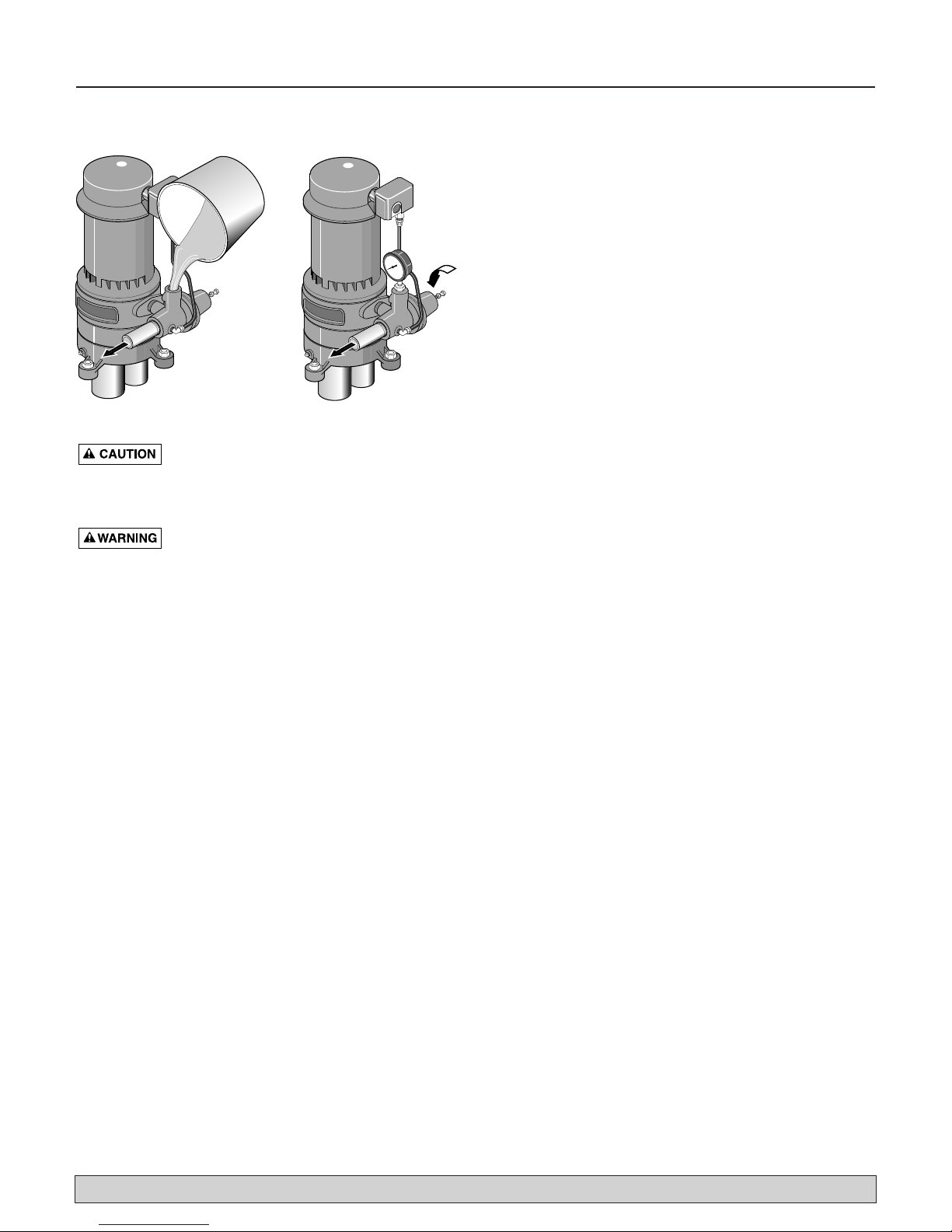
Operation 11
PRIMING THE PUMP (Figure 13)
NEVER run pump dry. Running pump without water may cause pump to overheat, damaging seal
and possibly causing burns to persons handling pump.
Fill pump with water before starting.
NEVER run pump against closed discharge.
To do so can boil water inside pump, causing hazardous
pressure in unit and possibly scalding persons handling
pump.
NOTICE: Open water system faucets before priming
pump for the first time.
1. Remove pressure gauge.
A. Close regulator valve (turn clockwise).
B. Fill pump and suction pipe with water.
C. Replace pressure gauge, using teflon tape on
thread; tighten gauge.
IMPORTANT: If a priming tee and plug have been provided for a long horizontal run, fill suction pipe through
tee and replace plug. (Remember: teflon tape plug.)
2. Start Pump:
Pressure should build rapidly to 50 PSI (345 kPa) or
more as jet and pump prime.
IF NO PRESSURE OR NO WATER, REPEAT
STEP No.1 two or three times to remove entrapped
air from suction pipes.
3. If, after priming pump several times and no water is
pumped, make sure that:
A. Suction pipe is in the water and has no leaks.
NOTE: Air can leak in where water won’t leak out.
Make sure all joints are tight.
B. Control valve, check valve, or foot valve is
installed and operating correctly.
C. Pump is not trying to lift water more than 25 feet
(7.6M) (shallow well) or more than rated lift for
deep well jet used (including compensation for
horizontal piping). See “Performance and Jet
Chart” for your installation.
D. Pump is not airlocked, suction port should be
highest point in suction pipe; no sags in suction
pipe (run it straight and angled slightly upward
from well head to pump).
NOTE: For deep well installation, go to step 4.
Shallow well installations go to step 6.
4. Once unit has primed and pressure is stabilized,
slowly open regulator valve (turn counterclockwise)
until pressure falters (pressure gauge needle flutters).
Close control valve (turn clockwise) slightly until
pressure stabilizes. This setting provides maximum
flow.
5. Pump may draw well down far enough to lose its
prime. If so, close regulator valve until pressure is stable throughout pumping cycle. Close faucets and
allow pump to pressurize tank and shut off.
6. Check system by alternately opening and closing
faucets in the system. With faucets open, pressure
will drop until pump starts; with faucets closed, pressure will build up until pump shuts off.
7. There are conditions of deep well operation when the
regulator valve may be completely open without any
faltering of pressure. In this case, operate pump with
regulator valve open.
Figure 13 – Fill Pump
60
40
20
80
100
2360a 0697
2361a 0697

Repair Parts 12
For parts or assistance, call Flotec Customer Service at 1-800-365-6832
* Standard hardware item, available locally.
Key No. Part Description Qty. FP4432-01
1 Motor 1 A300EH
2 1/2" Connector 1 U43-13C
3 1/2" Locknut 1 *
4 Pressure Switch 1 U217-1228
5 1/4" Tubing 1 *
6 Pressure Regulator Assembly 1 J212-24E
7 Pump Adapter 1 L2-16A
8 3/8-16 x 1" Capscrew 2 *
9 #3 Woodruff Shaft Key 2 U65-15SS
10 Shaft Seal 1 17351-0101A
11 Spring Holder 1 J24-11
12 Impeller 2 J105-76P
13 Impeller Spacer 1 J43-23
14 Gasket 2 J20-11
15 Intermediate Volute 1 J101-26
16 Wear Ring 2 J23-10
17 Wear Ring 1 J23-11
18 Impeller Nut 1 U36-175D
19 Base Volute 1 J101-33
20 3/8 - 16 x 4-1/4" Capscrews 2 *
21 1/4" NPT Square Head Pipe Plug 1 *
2
1
3
13
14
4
15
16
5
17
60
40
20
7
80
100
6
12
18
14
8
9
16
19
10
11
21
20
12
1281 0705
 Loading...