

Flotec FPZS25T, FPZS33V, FPZS33T, FPZS50V, FPZS75V Owner's Manual
...
OWNER’S MANUAL
Submersible Plastic
Sump Pumps
NOTICE D’UTILISATION
Pompes submersibles en
plastique pour puisard
MANUAL DEL USUARIO
Bombas sumergibles de
plástico para sumidero
Installation/Operation/Parts
For further operating,
installation, or maintenance
assistance:
Call 1-800-365-6832
English ....................... Pages 2-7
Installation/Fonctionnement/Pièces
Pour plus de renseignements
concernant l’utilisation,
l’installation ou l’entretien,
Composer le 1 (800) 365-6832
Français ................. Pages 8-12
Instalación/Operación/Piezas
Para mayor información sobre el
funcionamiento, instalación o
mantenimiento de la bomba:
Llame al 1-800-365-6832
Español .................Paginas 13-19
293 Wright Street, Delavan, WI 53115
Phone: 1-800-365-6832
Fax: 1-800-526-3757
flotecwater.com
FPZS25T
FPZS33T, FPZS50T
© 2014 Pentair Ltd. All Rights Reserved. FP973 (05/09/14)
FPZS33V
FPZS50V, FPZS75V
For parts or assistance, call Flotec Customer Service at 1-800-365-6832
Safety 2
Im portant Safety
Instructions
SAVE THESE INSTRUCTIONS - This manual contains
important instructions that should be followed during
installation, operation, and maintenance of the product.
This is the safety alert symbol. When you see this
symbol on your pump or in this manual, look for
one of the following signal words and be alert to the
potential for personal injury!
indicates a hazard which, if not avoided,
will result in death or serious injury.
indicates a hazard which, if not avoided,
could result in death or serious injury.
indicates a hazard which, if not avoided,
could result in minor or moderate injury.
NOTICE addresses practices not related to
personalinjury.
Carefully read and follow all safety instructions in this
manual and on pump.
Keep safety labels in good condition. Replace missing
or damaged safety labels.
California Proposition 65 Warning
This product contains chemicals known to
the State of California to cause cancer or birth defects
or other reproductive harm.
1. Know the pump application, limitations, and potential
hazards.
2. Do not use in water with fish present. If any oil leaks
out of the motor it can kill fish.
3. Disconnect power before servicing.
4. Release all pressure within system before servicing
any component.
5. Drain all water from system before servicing.
6. Secure discharge line before starting pump. An
unsecured discharge line will whip, possibly causing
personal injury and/or property damage.
7. Check hoses for weak or worn condition before each
use, making certain that all connections are secure.
8. Periodically inspect sump, pump and system
components. Keep free of debris and foreign objects.
Perform routine maintenance as required.
9. Provide means of pressure relief for pumps whose
discharge line can be shut-off or obstructed.
10. Personal Safety:
a. Wear safety glasses at all times when working with
pumps.
b. Keep work area clean, uncluttered and properly
lighted – replace all unused tools and equipment.
c. Keep visitors at a safe distance from work area.
d. Make workshop child-proof – with padlocks, master
switches, and by removing starter keys.
11. When wiring an electrically driven pump, follow all
electrical and safety codes that apply.
12. This equipment is only for use on 115 volt
(single phase) and is equipped with an approved
3-conductor cord and 3-prong, grounding-type plug.
Risk of electric shock. Can shock, burn or
kill. This pump has not been investigated for use in
swimming pool areas. Pump is supplied with a grounding
conductor and grounding-type attachment plug. Be sure it
is connected only to a properly grounded grounding-type
receptacle.
Where a 2-prong wall receptacle is encountered, it must
be replaced with properly grounded 3-prong receptacle
installed in accordance with codes and ordinances that
apply.
13. All wiring should be performed by a qualified
electrician.
14. Make certain power source conforms to requirements
of your equipment.
15. Protect electrical cord from sharp objects, hot
surfaces, oil, and chemicals. Avoid kinking cord.
Replace or repair damaged or worn cords
immediately.
16.
Do not touch an operating motor. Modern motors can
operate at high temperatures.
17. Do not handle pump or pump motor with wet hands
or when standing on wet or damp surface, or in water.
Risk of electric shock. Can shock, burn or
kill. If your basement has water or moisture on floor, do
not walk on wet area until all power has been turned off.
If shut-off box is in basement, call electric company or
hydro authority to shut-off service to house, or call your
local fire department for instructions. Remove pump and
repair or re place. Failure to follow this warning can result
in fatal electrical shock.
Do not lift pump by power cord.
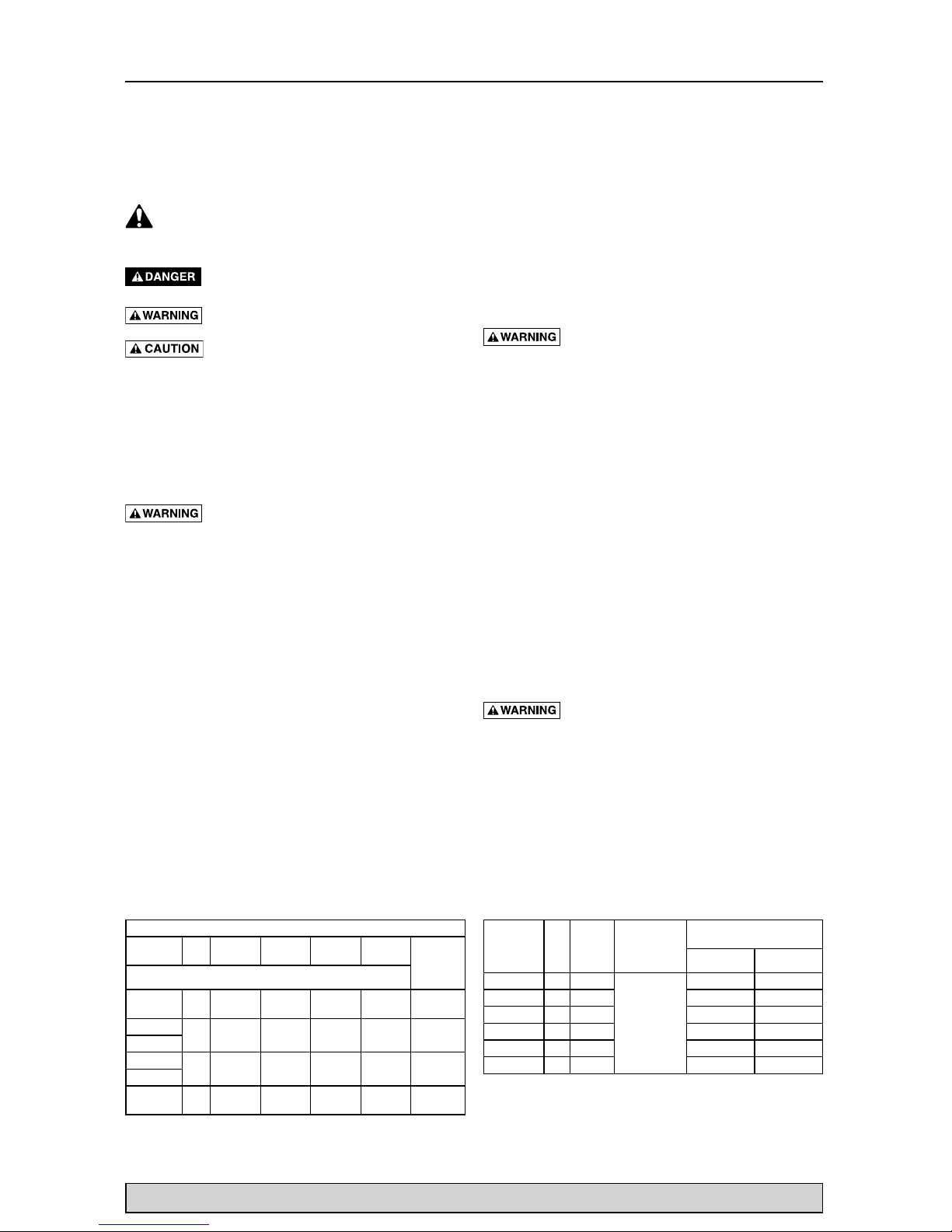
GPH (LPH) at total feet (m) of lift
Series HP
5
(1.5m)
10
(3m)
15
(4.6m)
20
(6.1m)
No flow
at height
shown
below
Capacity Gallons(L)/Hour
FPZS25T 1/4
2700
(10221)
2160
(8176)
1500
(5678)
-
20 ft
(6.1m)
FPZS33T
1/3
3060
(11583)
2400
(9085)
1680
(6359)
660
(2498)
22 ft
(6.7m)
FPZS33V
FPZS50T
1/2
3660
(13855)
3000
(11356)
2160
(8176)
960
(3634)
22 ft
(6.7m)
FPZS50V
FPZS75V 3/4
4200
(15899)
3540
(13400)
2820
(10675)
1800
(6814)
24 ft
(7.3m)
Series HP
Motor
Full
Load
Amps
Branch
Circuit Req.
(Amps)
Switch Setting in inches
(cm)
On Off
FPZS25T 1/4 3.9
15
14 (35.6) 5 (12.7)
FPZS33T 1/3 4.0 14 (35.6) 5 (12.7)
FPZS33V 1/3 4.0 7.5 (19.1) 3 (7.6)
FPZS50T 1/2 4.1 14 (35.6) 5 (12.7)
FPZS50V 1/2 4.1 7.5 (19.1) 3 (7.6)
FPZS75V 3/4 5.5 7.5 (19.1) 3 (7.6)
Performance Electrical & Switch Specifications
For parts or assistance, call Flotec Customer Service at 1-800-365-6832
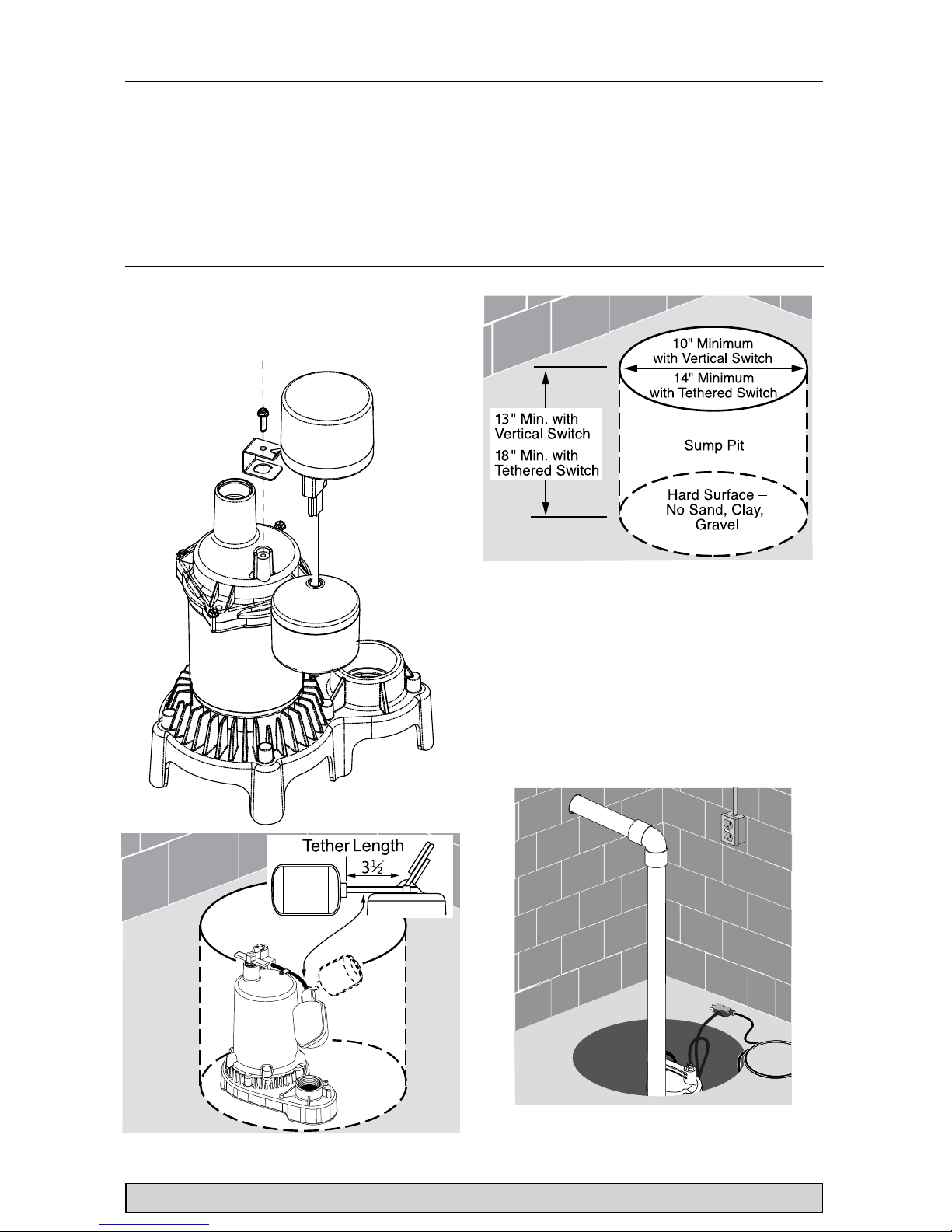
Float Switch Installation
Models equipped with vertical switches require some
assembly. Models with tethered float switches are ready
for use.
Installation
1. Install pump in sump pit with minimum diameter
of 10” (254mm) for models equipped with vertical
switches and 14” (356mm) for tethered float switch
models. Sump depth should be 18” (457mm) for
tethered models and 13” (330mm) for vertically
switched models. Construct sump pit of tile, concrete,
steel or plastic. Check local codes for approved
materials and for proper installation.
2. Install pump in pit so that switch operating
mechanism has maximum possible clearance.
3. Pump should not be installed on clay, earth or sand
surfaces. Clean sump pit of small stones and gravel
which could clog pump. Keep pump inlet screen clear.
NOTICE Do not use ordinary pipe joint compound on
plastic pipe. Pipe joint compound can weaken plastics.
Specifications . Installation 3
Specifications
Power supply required...................................115V, 60 HZ.
Liquid Temp. Range..........................32°F to 70°F(0°-21°C)
Individual Branch Circuit Required (min.).............15 Amps
Discharge:........................................................ 1-1/2” NPT
NOTICE Do not reduce size of discharge pipe or hose
below 1-1/4” diameter. If discharge is too small, pump will
overheat and fail prematurely.
This pump is designed for use in a residential sump only.
Only pump water with this pump.
NOTICE This unit is not designed as a waterfall or fountain
pump, or for applications involving salt water or brine!
Use with waterfalls, fountains, salt water or brine will void
warranty.
Do not use where water recirculates.
Not designed for use as a swimming pool drainer.
For parts or assistance, call Flotec Customer Service at 1-800-365-6832
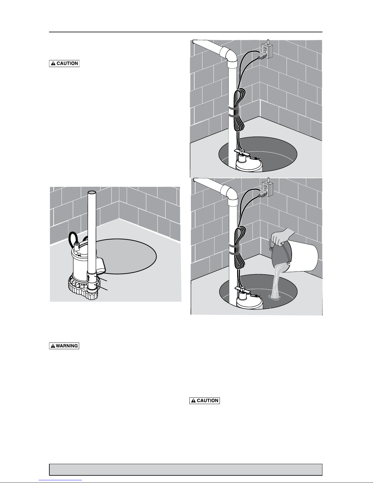
4. Install discharge plumbing. Use rigid plastic pipe and
wrap threads with
PTFE pipe thread sealant tape
.
Hand tighten pipe into pump plus 1-1/2 turns.
Risk of flooding. Can cause personal injury
and/or property damage. If a flexible discharge hose is
used, make sure pump is secured in sump to prevent
movement. Failure to secure pump may allow pump
movement, switch interference and prevent pump from
starting or stopping.
5. To reduce motor noise and vibrations, a short length
of rubber hose (1-7/8” (47.6mm) I.D., e.g. radiator
hose) can be connected into discharge line near pump
using suitable clamps.
6. Install an in-line check valve or an in-pump check
valve to prevent flow backwards through pump when
pump shuts off.
NOTICE If your check valve is not equipped with an
air bleed hole to prevent airlocking pump, drill a 1/8”
(3.2 mm) hole in discharge pipe just above where the
discharge pipe screws into the pump discharge. Be sure
the hole is below the waterline and the check valve to
prevent air locks.
7. Power Supply: Pump is designed for 115 V., 60 Hz.,
operation and requires a minimum 15 amp individual
branch circuit. Both pump and switch are supplied
with 3-wire cord sets with grounding-type plugs.
Switch plug is inserted directly into outlet and pump
plug inserts into opposite end of switch plug.
Risk of electric shock. Can shock, burn or
kill. Pump should always be electrically grounded to a
suitable electrical ground such as a grounded water pipe
or a properly grounded metallic raceway, or ground wire
system. Do not cut off round ground pin.
8. If pump discharge line is exposed to sub-freezing
weather conditions, portion of exposed pipe must
be installed so any water remaining will drain out or
down due to gravity. Failure to do this can cause water
trapped in discharge to freeze which could result in
damage to pump.
9. After piping, check valve and float switch have been
installed, the unit is ready for operation.
10. Check the pump operation by filling sump with water
and observing pump operation through one complete
cycle. For switch settings see the Electrical and Switch
Specifications chart on Page 2.
Risk of flooding. Can cause personal injury
and/or property damage. Failure to make this operational
check may lead to improper operation, premature failure,
and flooding.
Operation 4
Check valve
Air lock hole

For parts or assistance, call Flotec Customer Service at 1-800-365-6832
Operation ∙ Troubleshooting 5
Symptom Possible Cause(s) Corrective Action
Pump won’t start
or run.
Pump is not plugged in. Check and see if pump is plugged into a proper outlet.
Blown fuse. If blown, replace with fuse of proper size.
Low line voltage
If voltage under recommended minimum, check size
of wiring from main switch on property. If OK, contact
power company or hydro authority.
Defective motor. Replace pump.
Defective float switch. Replace float switch.
Impeller
If impeller won’t turn, remove lower pump body and
locate source of binding.
Float obstructed Remove obstruction.
Pump starts and
stops too often.
Backflow of water from piping Install or replace check-valve.
Faulty float switch Replace float switch.
Pump won’t shut
off
Defective float switch Replace float switch.
Restricted discharge (obstacle
or ice in piping)
Remove pump and clean pump and piping.
Float obstructed Remove obstruction.
Restricted intake screen
Remove the pump and clean the intake screen and the
impeller.
Pump operates
but delivers little
or no water
Low line voltage
If voltage under recommended minimum, check size
of wiring from main switch on property. If OK, contact
power company or hydro authority.
Something caught in impeller Remove the pump and clean out the impeller.
Worn or defective parts or
plugged impeller
Clean impeller if plugged; otherwise replace pump.
Check valve installed without
vent hole.
Drill a 1/16” - 1/8” (1.6mm-3.2mm) dia. hole between
pump discharge & check valve (1-2” above where the
discharge pipe screws into the pump discharge and
below the waterline).
Restricted intake screen Remove the pump and clean out the intake screen.
Check valve is installed either
backward or upside down
Be sure check valve is installed correctly.
Operation
Risk of electric shock. Can shock, burn or
kill. Do not handle a pump or pump motor with wet
hands or when standing on wet or damp surface, or in
water.
1. Shaft seal depends on water for lubrication. Do not
operate pump unless it is submerged in water as seal
may be damaged if allowed to run dry.
2. Motor is equipped with automatic reset thermal
protector. If temperature in motor should rise, switch
will cut off all power before damage can be done
to motor. When motor has cooled, switch will reset
automatically and restart motor. If protector trips
repeatedly, pump should be removed and checked.
Low voltage, long extension cords, clogged impeller,
very low head or lift, or a plugged or frozen discharge
pipe, etc., could cause protector to trip.
3. Pump will not remove all water. If operating a pump
manually and suddenly no water comes out of the
discharge hose, shut off the unit immediately. The unit
has broken prime due to a very low water level.
Risk of electric shock. Can shock, burn or
kill. Before attempting to check why unit has stopped
operating, disconnect power from unit.
Troubleshooting
For parts or assistance, call Flotec Customer Service at 1-800-365-6832
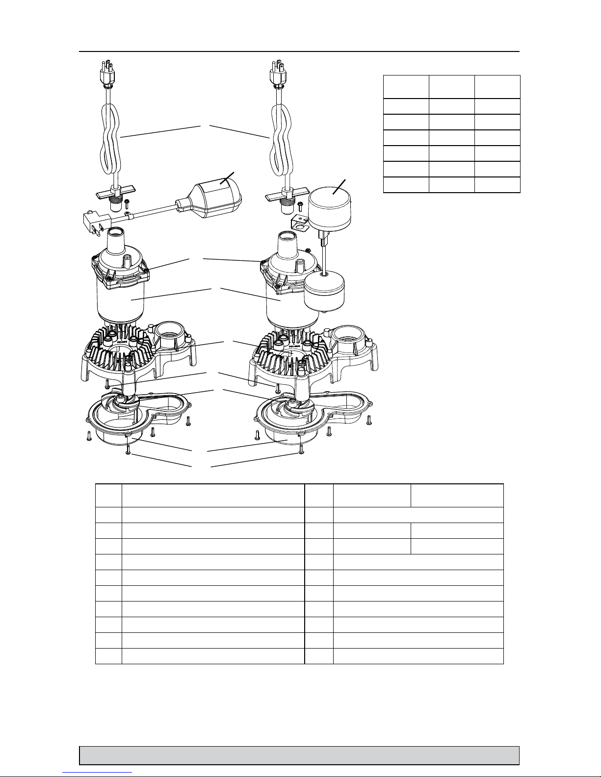
Repair Parts 6
**If motor fails, replace entire pump.
• Purchase locally
Model Impeller
Upper
Volute
FPZS25T PS5-285 PS1-325
FPZS33T PS5-286 PS1-325
FPZS33V PS5-286 PS1-325
FPZS50T PS5-286 PS1-327
FPZS50V PS5-286 PS1-327
FPZS75V PS5-287 PS1-327
Ref Description Qty
FPZS25T, FPZS33T,
FPZS50T
FPZS33V, FPZS50V.
FPZS75V
1 Power Cord Assembly 1 PS117-54-TSU
2 Tethered Float Assembly 1 FP18-15BD -
3 Vertical Float Switch Assembly 1 - FPS17-66
4 Screw #8-32 x 7/8” 4 •
5 Motor 1 **
6 Upper Volute 1 See Chart
7 Screw #8-32 x 1/2” 5 •
8 Impeller 1 See Chart
9 Lower Volute 1 PS1-326
10 Screw #8 x 5/8” coarse thread “Sheet/Metal Screw” 6 •
PLASTIC SERIES
1
2
3
4
6
8
9
10
 Loading...