

Flotec FPSE3200A, FPSE2800A, FPSE3601A Owner's Manual
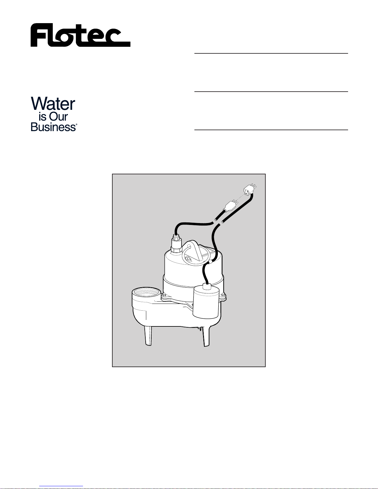
OWNER’S MANUAL
Submersible Solids
Handling Pumps
NOTICE D’UTILISATION
Pompes submersibles
pour les matières solides
MANUAL DEL USUARIO
Bombas submergibles para el
manejo de líquidos con sólidos
Installation/Operation/Parts
For further operating, installation,
or maintenance assistance:
Call 1-800-365-6832
English . . . . . . . . . . . . . . Pages 2-6
Installation/Fonctionnement/Pièces
Pour plus de renseignements
concernant l’utilisation,
l’installation ou l’entretien,
Composer le
1 (800) 365-6832
Français . . . . . . . . . . . Pages 7-11
Instalación/Operación/Piezas
Para mayor información sobre el
funcionamiento, instalación o
mantenimiento de la bomba:
Llame al 1-800-365-6832
Español . . . . . . . . . .Paginas 12-16
P.O. Box 342, Delavan, WI 53115
Phone: 1-800-365-6832
Fax: 1-800-526-3757
E-Mail: info@flotecwater.com
Web Site: http://www.flotecwater.com
©2005 S185 (Rev. 4/18/05)
3601A SERIES
®
412 0897ASB/NF
Safety 2
READ AND FOLLOW
SAFETY INSTRUCTIONS!
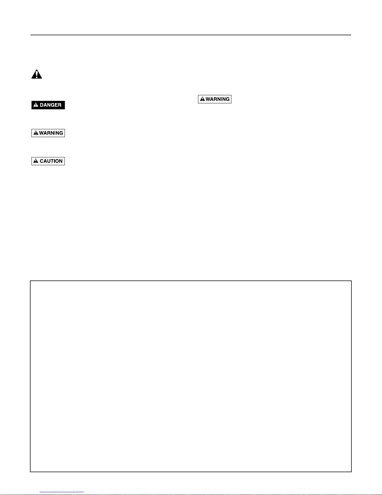
This is the safety alert symbol. When you see this
symbol on your pump or in this manual, look for
one of the following signal words and be alert to the
potential for personal injury:
warns about hazards that will cause serious
personal injury, death or major property damage if
ignored.
warns about hazards that can cause serious
personal injury, death or major property damage if
ignored.
warns about hazards that will or can cause
minor personal injury or property damage if ignored.
The label NOTICE indicates special instructions which
are important but not related to hazards.
Carefully read and follow all safety instructions in this
manual and on pump.
Keep safety labels in good condition.
Replace missing or damaged safety labels.
1. Read this manual carefully. Failure to follow these
instructions could cause serious bodily injury and/or
property damage.
2. Check your local codes before installing. You must
comply with their rules.
3. Vent sewage or septic tank according to local codes.
4. Do not install pump in any location classified as
hazardous by National Electrical Code, ANSI/NFPA
70-1990.
Hazardous voltage. Can shock, burn or
cause death. During operation, the pump is in water.
To avoid fatal shocks, proceed as follows if pump needs
servicing:
5A. Disconnect power to outlet box before unplugging
pump.
5B. Take extreme care when changing fuses. Do not
stand in water or put your finger in fuse socket.
5C. Do not modify cord and plug. When using cord and
plug, plug into a grounded outlet only. When wiring
to a system control, connect pump ground lead to
system ground.
6. Do not run pump dry. Dry running can overheat
pump, (causing burns to anyone handling it) and will
void warranty.
7. Pump normally runs hot. To avoid burns when ser-
vicing pump, allow it to cool for 20 minutes after
shut-down before handling it.
8. In normal service, motor should not need oiling.
Motor has been filled at the factory with a special
oil.
AT TACH ORIGINAL RECEIPT HERE FOR WARRANTY CONSIDERATION.
FLOTEC warrants that the products specified in this warranty are free from defects in material or workmanship.
If within the duration of product use by the product owner, any FLOODMATE
®
7000 (FP0S6000A), IRONMATE
®
(FPSC4550A), Sewage Ejector (FPSE3601A), Pedestal Pump (FPPSS5000), or Utility Pump (FPSC1725X), shall prove to
be defective, it shall be repaired or replaced at FLOTEC’s option, subject to the terms and conditions set forth below.
General Terms and Conditions
Owner must pay all labor and shipping charges necessary to replace product covered by this warranty. This warranty
shall not apply to acts of God, nor shall it apply to products which, in the sole judgement of FLOTEC, have been subject to negligence, abuse, accident, misapplication, tampering, alteration; nor due to improper installation, operation,
maintenance or storage; nor to excess of recommended maximums as set forth in the owner’s manual.
Requests for service under this warranty shall be made by returning the product to the Retail outlet or to FLOTEC as
soon as possible after the discovery of any alleged defect. FLOTEC will subsequently take corrective aciton as promptly
as reasonably possible.
This warranty sets forth FLOTEC’s sole obligation and purchaser’s exclusive remedy for defective products.
FLOTEC SHALL NOT BE RESPONSIBLE FOR ANY CONSEQUENTIAL, INCIDENTAL, OR CONTINGENT DAMAGES
WHATSOEVER. THE FOREGOING WARRANTY IS EXCLUSIVE AND IN LIEU OF ALL OTHER EXPRESS WARRANTIES,
IMPLIED WARRANTIES, INCLUDING BUT NOT LIMITED TO THE IMPLIED WARRANTIES OF MERCHANTABILITY
AND FITNESS FOR A PARTICULAR PURPOSE.
Some states do not allow the exclusion or limitation of incidental or consequential damages or limitation on how long
an implied warranty lasts, so the above limitations or exclusions may not apply to you. Although this warranty identified specific remedies you may also have other rights and remedies.
FLOTEC • P.O. Box 342 • Delavan, WI U.S.A. 53115
Phone: 1-800-365-6832 • Fax: 1-800-526-3757
E-Mail: info@flotecwater.com • Web Site: http://www.flotecwater.com
Specifications / Performance / Installation 3
INSTALLATION
(See Figure 1 for Typical Installation instructions.)
Pump must be level when operating. If
motor is tilted, internal start/run switch may overheat and
damage motor.
Risk of electrical shock. Can burn or kill.
Do not lift pump by power cord. See “Cord Lift Warning”
on Page 5. Do not hang pump from discharge pipe or
power cord.
1. Install the pump on a solid, level foundation, or in a
sump pit constructed of tile, concrete, steel or plastic. The recommended minimum diameter of the
sump pit is 18" (46cm) diameter and the minimum
recommended depth is 30" (76cm). Check local
codes for approved materials.
NOTICE: Pump should not be installed on clay, earth
or sand surfaces. Clean the area around the pump of
small stones and gravel which could clog the pump.
Keep the pump inlet screen clear.
2. Thread a 2” discharge pipe into the pump 2” NPT
discharge port. Be careful to avoid stripping or crossing threads.
Piping – Effluent Applications
(3/4" or Less Solids)
Piping must be 1-1/2" minimum to carry volume of
pump discharge. Check local codes to determine if a
check valve is required in your system. In cold climates,
check valves are not used to prevent effluent from freezing in piping.
Piping – Sewage Applications
(2" or Less Solids)
In any case, piping must not be smaller than pump
discharge.
When installed in a sewage system, pipe must be capable
of handling semi-solids of at least 2” (5.1 cm) diameter.
The rate of flow in the discharge pipe must keep any
solids present in suspension in the fluid. To meet minimum flow requirements (2 feet (.6 m) per second in discharge line), size pipe as follows:
A Pipe Size Of: Will Handle a Flow Rate Of:
1-1/2” (3.8 cm) 12 GPM (45 LPM)
2” (5.1 cm) 21 GPM (79 LPM)
2-1/2” (6.3 cm) 30 GPM (113 LPM)
3” (7.6 cm) 48 GPM (181 LPM)
NOTICE: Use Teflon™ tape on pipe connections. Do
not use ordinary pipe joint compound on plastic pipe or
pump. Pipe joint compound can attack plastics and damage pump.
TM
E.I. DuPont de Nemours and Company Corporation.
For parts or assistance, call Flotec Customer Service at 1-800-365-6832
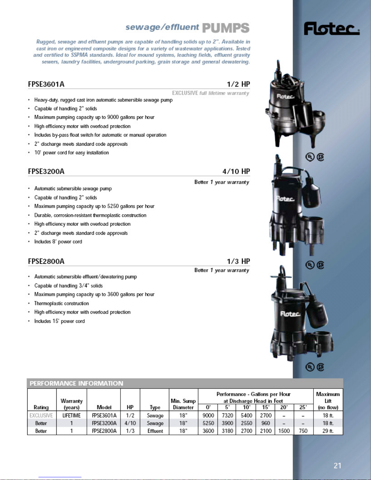
GPH (LITERS) AT DISCHARGE FT. OF HEAD
5 (1.5m) 10 (3m) 15 (4.6m) 20 (6.1m) 25 (7.6m)
FPSE3601A 7320(27,709) 5400(20,441) 2700(10,221) – –
PERFORMANCE
FPSE Individual Branch Circuit Dual Element Time
Model H.P. Voltage Required (Amps) Delay Fuse Amps
3601A 1/2 115 20 20
SPECIFICATIONS
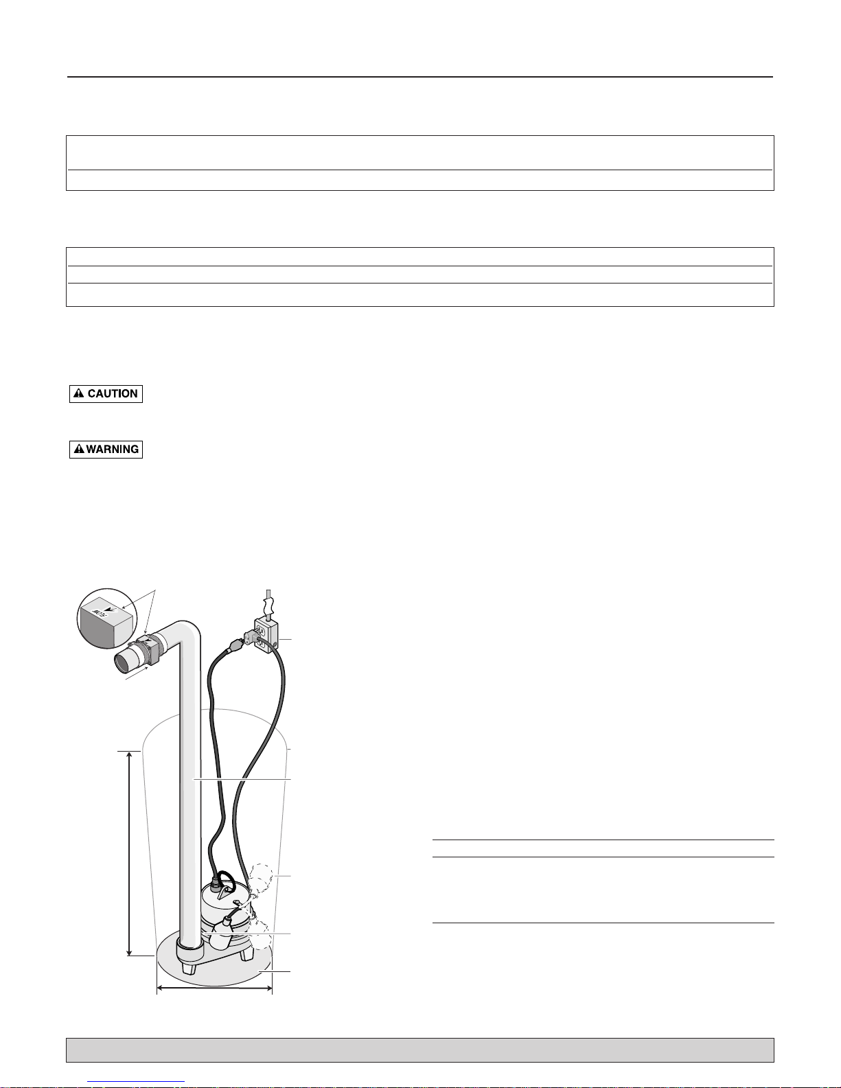
Figure 1
Flow
Directional
Arrow
115V Properly
Grounded
Outlet
2" Checkvalve
Do Not Mount
Vertically
Sump Pit
2" Discharge
Pipe
30"
18"
Be sure the
float switch can
swing through
it's entire arc.
Drill a 3/16"
vent hole here.
Install pump on
a hard, level surface.

Electrical / Operation / Service 4
3. To reduce motor noise and vibrations, a short length
of rubber hose can be connected into discharge line
near pump using suitable clamps.
4. If the pump discharge line is exposed to outside subfreezing atmosphere, then the portion of line
exposed must be installed so any water remaining in
pipe will drain to outfall by gravity. Failure to do this
can cause water trapped in discharge to freeze
which could result in damage to pump.
5. Install a 2” check valve in the horizontal portion of
the discharge pipe. Make certain, the flow indicating
arrow, points away from the pump. This check valve
will keep the water from either running back into the
basin or into the area being pumped out when the
pump is not running. Check valve should be a free
flow valve that will easily pass solids.
NOTICE: For best performance of check valve when
handling solids, do not install it with discharge angled
more than 45° above the horizontal. Do not install check
valve in a vertical position as solids may settle in valve
and prevent opening on startup.
6. Drill a 3/16” (4.7mm) hole in discharge pipe about
1"-2” (2.5 - 5.1cm) above pump discharge connection (but below check valve) to prevent airlocking
the pump.
7. Insert the float switch piggy-back plug into a properly grounded outlet and the pump plug into the piggyback plug.
8. Check the installation by observing the pump operation through one complete cycle. Make sure that no
parts of the assembly interfere with the float switch.
Risk of flooding. May cause personal injury
or property damage. Failure to make this operational
check may lead to improper operation, premature failure, and flooding.
ELECTRICAL
Hazardous voltage. Can shock, burn, or
cause death. When installing, operating, or servicing this
pump, follow safety instructions listed below.
Step 1. DO NOT splice the electrical power cord.
Step 2. DO NOT allow electrical cord plug to be sub-
merged.
Step 3. DO NOT use extension cords. They are a fire
hazard and can reduce voltage sufficiently to prevent pumping and/or damage motor.
Step 4. DO NOT handle or service pump while it is con-
nected to power supply.
Step 5. DO NOT remove grounding prong from plug or
modify plug.To protect against electrical shock,
the power cord is a three-wire conductor and
includes a 3-prong grounded plug. Plug pump
into a 3-wire, grounded, grounding-type receptacle. Connect pump according to electrical codes
that apply.
For automatic operation, plug or wire pump into an automatic float switch or pump controller. Pump will run continuously when plugged directly into an electrical outlet.
Connect or wire pump to its own individual branch circuit
with no other outlets or equipment in the circuit. Size
fuses or circuit breakers according to chart on Page 3.
Risk of electrical shock and fire. Can burn or
cause death. Be sure that power supply information
(Voltage/Hertz/Phase) on pump motor nameplate matches
incoming power supply exactly. Install pump according to
all electrical codes that apply.
OPERATION
NOTICE: Do not allow pump to run in a dry sump. It
will void the warranty and may damage the pump.
An automatic overload protector in the motor will pro-
tect motor from burning out due to overheating/overloading. When motor cools down, overload protector will
automatically reset and start motor.
If overload trips frequently, check for cause. It could be a
stuck impeller, wrong/low voltage, or electrical failure in
motor. If an electrical failure in the motor is suspected,
have it serviced by a competent repairman.
Pump is permanently lubricated. No oiling or greasing is
required.
SERVICE
Hazardous voltage. Can shock, burn, or
cause death. Before removing pump from basin for ser-
vice, always disconnect electrical power to pump and
control switch.
Risk of electrical shock. Can burn or kill.
Do not lift pump by power cord. See “Cord Lift Warning”
on Page 5.
Submerge pump in a disinfectant solution (chlorox or
chlorine) for at least one hour before disassembling
pump.
The pump motor contains a special lubricating oil which
should be kept clean and free of water at all times.
Check operation by filling sump with water and observing pump operation through one complete cycle.
For parts or assistance, call Flotec Customer Service at 1-800-365-6832
Service / Troubleshooting 5
For parts or assistance, call Flotec Customer Service at 1-800-365-6832
A. Pump fails to operate:
B. Pump fails to empty sump:
C. Pump will not shut off:
Risk of sudden starts. Can result in electrical
shock or pinching of hands or tools. If power to pump is on
when thermal overload resets, pump may start without
warning. Disconnect power before servicing pump.
1. Check to be sure that power cord is securely plugged into outlet. Disconnect power to
outlet before handling pump or motor.
2. Check to be sure you have electrical power.
3. Check that liquid fluid level is high enough to activate switch or controller.
4. Check to be sure that 3/16" (4.7 mm) vent hole in discharge pipe is not plugged.
5. Check for blockage in pump inlet, impeller, check valve or discharge pipe.
6. Thermal overload may have tripped. Test start pump; if it starts and then stops immediately, disconnect from power source for 30 minutes to allow motor to cool, then reconnect to power source. Check for cause of overheating/overloading.
7. Check the float switch operation for maximum possible clearance.
1. Be sure all valves in discharge valve are fully open.
2. Clean out discharge pipe and check valve.
3. Check for blockage in pump inlet or impeller.
4. Pump not sized properly. A higher capacity pump may be required.
5. Check the float switch operation for maximum possible clearance.
1. Check switch or controller automatic floats for proper operation, location and clearance.
See installation instructions for switch/controller.
2. If pump is completely inoperative or continues to malfunction, consult your local
serviceman.
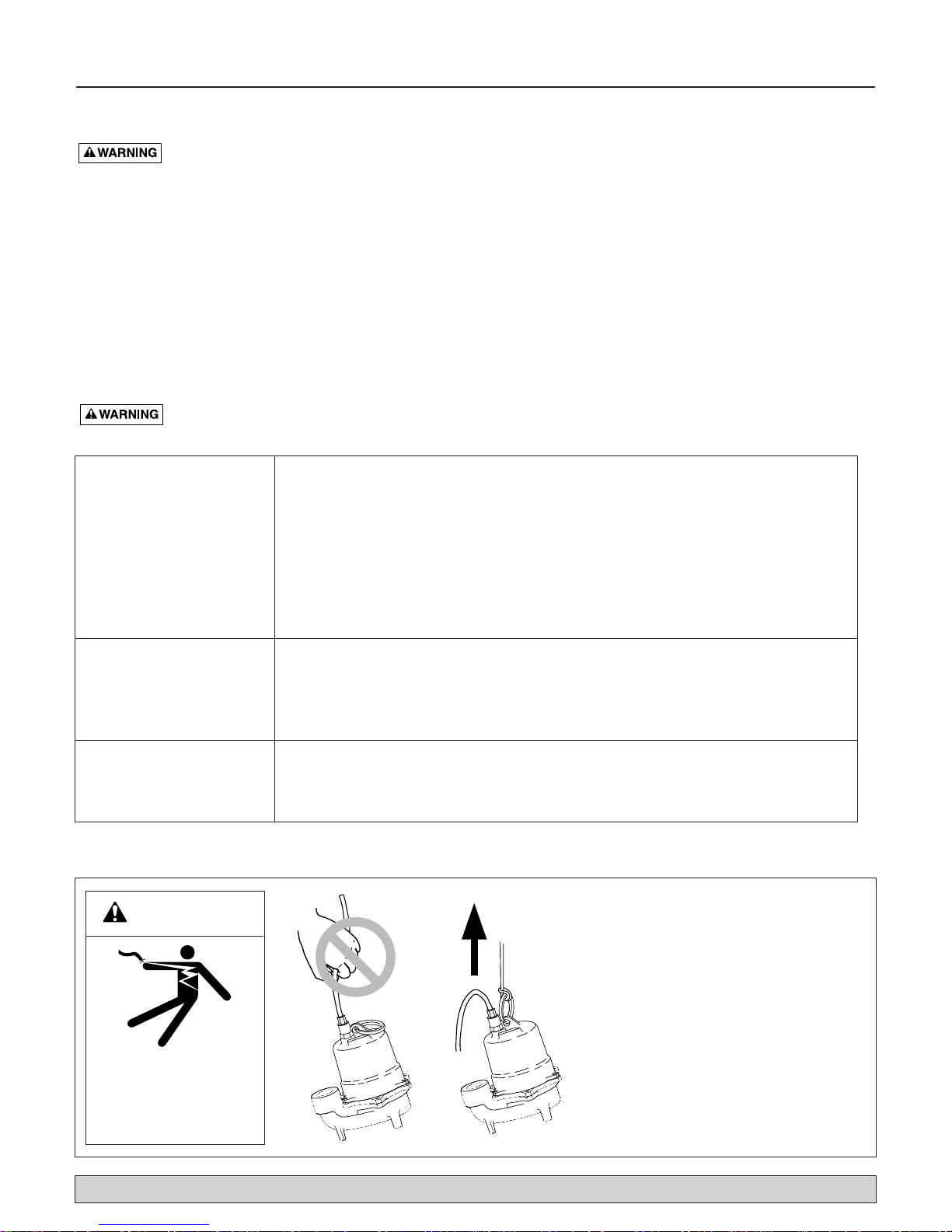
1. Attempting to lift or support pump by
power cord can damage cord and cord
connections.
2. Cord may pull apart, exposing bare
wires with possibility of fire or electrical
shock.
3. Lifting or supporting pump by power
cord will void warranty.
4. Use lifting ring or handle on top of
pump for all lifting/lowering of pump.
Disconnect power to pump before doing
any work on pump or attempting to
remove pump from sump.
Risk of electrical
shock.
Can burn or kill.
Do not lift pump by
power cord.
WARNING
TROUBLESHOOTING
Risk of flooding. May cause personal injury
or property damage. Failure to make this operational
check may lead to flooding and premature failure.
NOTICE: This unit is not designed for applications
involving salt water or brine! Use with salt water or brine
will void warranty.
 Loading...