

Flotec Floodmate 7000, FP0S6000A Owner's Manual
OWNER’S MANUAL
Submersible
Sump Pump
NOTICE D’UTILISATION
pompes submersibles
pour puisard
MANUAL DEL USUARIO
bombas’ sumergibles
para sumideros
Installation/Operation/Parts
For further operating, installation,
or maintenance assistance:
Call 1-800-365-6832
English . . . . . . . . . . . . . . . Pages 2-4
Installation/Fonctionnement/Pièces
Pour plus de renseignements
concernant l’utilisation,
l’installation ou l’entretien,
Composer le
1 (800) 365-6832
Français . . . . . . . . . . . . . Pages 5-7
Instalación/Operación/Piezas
Para mayor información sobre el
funcionamiento, instalación o
mantenimiento de la bomba:
Llame al 1-800-365-6832
Español . . . . . . . . . . . .Paginas 8-10
293 Wright Street, Delavan, WI 53115
Phone: 1-800-365-6832
Fax: 1-800-526-3757
Web Site: FlotecWater.com
© 2011 FP525 (6/17/2011)
FP0S6000A
2
For parts or assistance, call Flotec Customer Service at 1-800-365-6832
READ AND FOLLOW
SAFETY INSTRUCTIONS!
This is the safety alert symbol. When you see this sym-
bol on your pump or in this manual, look for one of the following signal words and be alert to the potential for personal
injury!
warns about hazards that will cause serious per-
sonal injury, death or major property damage if ignored.
warns about hazards that can cause serious
personal injury, death or major property damage if ignored.
warns about hazards that will or can cause
minor personal injury or property damage if ignored.
The label
NOTICE
indicates special instructions which are impor-
tant but not related to hazards.
Make sure installation complies with all electrical / plumbing
codes.
Hazardous Voltage. Can cause serious or fatal
electrical shock. Disconnect power to pump before servicing.
If floor is wet, disconnect power at main electrical service
before walking on it. Do not stand in water or touch metal
surfaces when switching circuit breaker or removing/installing
fuses.
Pump is equipped with a three-prong, grounding cord and
plug. Do not modify cord or plug. Plug this unit into a 115V
outlet, on an individual branch circuit, with a Class A, 10 amp
GFCI (Ground Fault Circuit Interrupter).
Do not use in explosive environments. Pump
water only with this pump. Inspect sump, pump and system
components monthly. Keep free of debris and foreign objects.
Perform routine maintenance as required.
Risk of flooding. If a flexible discharge hose
is used, pump may move around in sump when motor
starts. If it moves far enough so that switch hits side of sump,
switch may stick and prevent pump from starting. Make sure
pump is secured so it cannot move around in sump.
Electrically powered sump pumps normally give many years of
trouble-free service when correctly installed, maintained, and
used. However, unusual circumstances (interruption of power to
the pump, dirt/debris in the sump, flooding that exceeds the
pump’s capacity, electrical or mechanical failure in the pump, etc.)
may prevent your pump from functioning normally. To prevent
possible water damage due to flooding, consult your dealer about
installing a secondary sump pump, a DC backup sump pump,
and/or a high water alarm. See the “Troubleshooting Chart” in this
manual for information about common sump pump problems and
remedies. For more information, see your retailer, call Flotec customer service at 1-800-365-6832 or visit our website at
www.flotecwater.com.
NOTICE
: This unit is not designed for applications involving salt
water or brine! Use with salt water or brine will void warranty.
SPECIFICATIONS
Power Supply Required.............................................115V, 60HZ.
Liquid Temperature Range....................................77°F Maximum
Individual Branch Circuit Required (minimum) .............10.0 Amps
Motor Full Load (maximum)............................................7.5 Amps
Discharge (Insert for 1-1/4” also included).......1-1/2" Slip Adapter
NOTICE
: Do not use where fish are present. Any leakage of oil
from the motor into the water can kill fish.
Not designed for use as a swimming pool drainer.
Do not use where water recirculates.
PERFORMANCE
OPERATION
Pump is equipped with an automatic float switch which starts
pump when water level reaches 10"-12". Pump automatically
turns off when level drops to 4" - 6".
GENERAL GUIDELINES
Sump should be at least 18" deep. Inside diameter of sump
should be at least 14".
Check Valve is built-in. If necessary to allow flowback from discharge pipe to sump:
• Drill a 1/8" diameter hole in the discharge pipe 2” above the
pump. Pump should be installed below the basement floor
level.
Discharge Pipe: Pump is supplied with flexible connector that fits
1-1/2” PVC or ABS pipe. Adapter insert allows use of 1-1/4” PVC
or ABS pipe. PVC or ABS adapters may be purchased to fit other
discharge pipe sizes.
ELECTRICAL
Hazardous voltage. Can cause severe or fatal
electrical shock. Pump is supplied with a grounding conductor
and grounding-type attachment plug. To reduce risk of electric
shock, be certain that it is connected only to a properly grounded, grounding type receptacle.
Plug this unit into a 115V outlet, on an individual branch circuit,
with a Class A, 10 amp GFCI (Ground Fault Circuit Interrupter).
For installation of such a circuit, consult a licensed electrician.
ELECTRICAL SERVICE
AC power outlets should be on a separate 10 amp individual
branch circuit; 115V, AC, 60 cycles, and located within 8 ft. of
sump. Ground terminal on pump cord plug is provided for your
protection. DO NOT REMOVE!
PUMP INSTALLA TION
1. Remove debris and foreign material etc., from sump to pre-
vent clogging.
2. Place pump on smooth, level surface. Use building blocks or
bricks to elevate pump screen a minimum of 2" above mud,
sand or loose stones.
3. Locate pump in center of pit so pump housing and float con-
trol will not come in contact with side of pit and create operational problems.
4. Slip connector hose over pump discharge. Install and tighten
first clamp.
5. Place second clamp loosely over connector hose.
6. Slip connector hose over discharge pipe. Clamp hose tightly
with second clamp. Run discharge piping to nearest outlet,
depending on local plumbing codes. Discharge piping should
be as short as possible to reduce pipe friction losses.
Discharge pipe diameter should be equal to or larger than discharge size of pump. Smaller pipe diameters will restrict
capacity of pump and reduce performance.
7. Securely anchor flexible discharge line if used. If line is not
secure, pump may tip during operation.
Total Lift in Feet 5' 10' 15' 20' 25'
Capacity in GPH 6000 5040 3840 2340 0
3
For parts or assistance, call Flotec Customer Service at 1-800-365-6832
AUTOMATIC FLOAT SWITCH
1. Install pump following installation and operating instructions.
2. Automatic float switch is sealed and factory adjusted for
most home sumps. Turn-on water level is 10" - 12" above
pump base. Turn-off water level is 4" - 6".
3. Be sure float clearance is at least 8". For best performance,
the sump diameter must be 14” and the sump depth must be
18".
4. Plug piggyback switch cord into 115V AC outlet. Then, plug
pump into piggyback switch cord.
NOTICE
: Minimum recommended turn-off level is 2" above
pump base.
Do not allow cord to interfere with float control motion or to
drape over pump motor. With electrician's tape, secure cord
to discharge pipe for cord protection.
OPERATIONAL CHECK
AUTOMATIC FLOAT SWITCH
1. Fill sump with 12"-14" of water to check operation and tightness of connections. During first automatic cycle, it may take
30 seconds or more before pump is primed and pumping.
Turn-on will occur approx. 11" above pump base.
2. Check turn-off position. Turn-off will occur approx. 5" above
pump base.
3. If the pump does not operate, check for:
• an obstructed float switch
• a blown fuse
• proper voltage.
REPAIR PARTS LIST
TROUBLESHOO TING CHART
Hazardous Voltage. Can cause serious or fatal electrical shock. Disconnect power to pump before servicing.
SYMPTOM PROBABLE CAUSE(S) CORRECTIVE ACTION
Motor does not run. Blown fuse Replace.
Tripped circuit Reset.
Disconnected plug Reinstall.
Corroded plug Clean prongs.
Inadequate water level Add water and test.
Tripped overload Allow pump to cool.
Defective switch Adjust float; replace switch.
Defective motor Replace pump.
Float in wrong position See Automatic Float Switch section.
Motor hums but flow Impeller jammed Unplug pump and unclog.
is reduced or no flow Plugged check valve Unplug pump and unclog.
Blocked screen Unplug pump and clean screen.
Line leak Unplug pump and repair.
Worn Impeller Unplug pump and replace pump impeller.
Defective motor Replace pump.
Runs continuously Plugged screen Unplug pump and clean screen.
Defective switch Replace switch.
Float obstruction See Automatic Float Switch section.
NOTICE
: A plugged screen can be mistaken for a faulty switch.
Unlike other pumps, screen and impeller design of pump can provide significant flow, even when screen is nearly plugged. If pump
RUNS CONTINUOUSLY or for EXTENDED PERIODS between
turn-offs – FIRST check for a DIRTY SCREEN.
Model
Description FP0S6000A-08
Discharge Connector - U74-68
1-1/2" (incl. 2 clamps)
Power Cord PS117-98-TSU
Automatic Float Switch FP18-15BD
Screen 12924
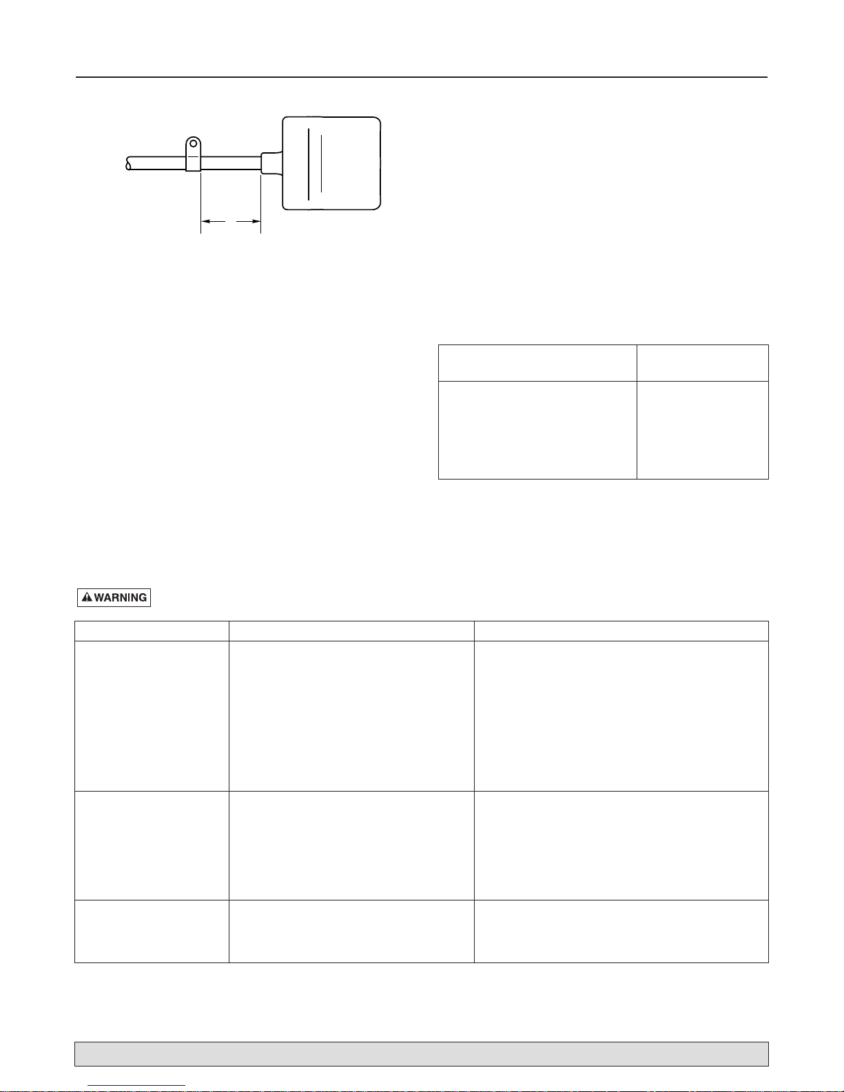
3"
(76 mm)
NOTICE
: Switch tether is factory set at 3" for sump use.
DO NOT change tether length.
4
For parts or assistance, call Flotec Customer Service at 1-800-365-6832
Retain Original Receipt For Warranty Eligibility
Limited Warranty
This Limited Warranty is effective June 1, 2011 and replaces all undated warranties and warranties dated before June 1, 2011.
FLOTEC warrants to the original consumer purchaser (“Purchaser” or “You”) that its products are free from defects in material
and workmanship for a period of twelve (12) months from the date of the original consumer purchase. If, within twelve (12)
months from the original consumer purchase, any such product shall prove to be defective, it shall be repaired or replaced at
FLOTEC’s option, subject to the terms and conditions set forth herein. Note that this limited warranty applies to manufacturing
defects only and not to ordinary wear and tear. All mechanical devices need periodic parts and service to perform well. This
limited warranty does not cover repair when normal use has exhausted the life of a part or the equipment.
The original purchase receipt and product warranty information label are required to determine warranty eligibility. Eligibility is
based on purchase date of original product – not the date of replacement under warranty. The warranty is limited to repair or
replacement of original purchased product only, not replacement product (i.e. one warranty replacement allowed per purchase).
Purchaser pays all removal, installation, labor, shipping, and incidental charges.
For parts or troubleshooting assistance, DO NOT return product to your retail store. Contact FLOTEC Customer Service
at 1–800–365–6832.
Claims made under this warranty shall be made by returning the product (except sewage pumps, see below) to the retail outlet
where it was purchased or to the factory immediately after the discovery of any alleged defect. FLOTEC will subsequently take
corrective action as promptly as reasonably possible. No requests for service will be accepted if received more than 30 days
after the warranty expires. Warranty is not transferable and does not apply to products used in commercial/rental applications.
Sewage Pumps
DO NOT return a sewage pump (that has been installed) to your retail store. Contact FLOTEC Customer Service. Sewage
pumps that have seen service and been removed carry a contamination hazard with them.
If your sewage pump has failed:
• Wear rubber gloves when handling the pump;
• For warranty purposes, return the pump’s cord tag and original receipt of purchase to the retail store;
• Dispose of the pump according to local disposal ordinances.
Exceptions to the Twelve (12) Month Limited Warranty
Product Warranty Period
FP0F360AC, FP0FDC 90 days
FP0S1775A, FP0S1790PCA, FP0S2400A, FP0S2450A, FP0S4100X, FP2800DCC,
FPCP-20ULST, FPPSS3000, FPSC2150A, FPSC3150A, FPSC3350A 2 Years
4” Submersible Well Pumps, FP0S3200A, FP0S3250A, FP0S6000A, FPSC1725X,
FPSC2200A, FPSC2250A, FPSE3601A, FPPSS5000 3 Years
FP7100 Series Pressure Tanks, E100ELT, E3305TLT, E3375TLT, E5005TLTT, E50TLT,
E50VLT, E75STVT, E75VLT, FPSC3200A, FPSC3250A, FPSC4550A 5 Years
General Terms and Conditions; Limitation of Remedies
You must pay all labor and shipping charges necessary to replace product covered by this warranty. This warranty does not
apply to the following: (1) acts of God; (2) products which, in FLOTEC’s sole judgment, have been subject to negligence, abuse,
accident, misapplication, tampering, or alteration; (3) failures due to improper installation, operation, maintenance or storage; (4)
atypical or unapproved application, use or service; (5) failures caused by corrosion, rust or other foreign materials in the
system, or operation at pressures in excess of recommended maximums.
This warranty sets forth FLOTEC’s sole obligation and purchaser’s exclusive remedy for defective products.
FLOTEC SHALL NOT BE LIABLE FOR ANY CONSEQUENTIAL, INCIDENTAL, OR CONTINGENT
DAMAGES WHATSOEVER.
THE FOREGOING LIMITED WARRANTIES ARE EXCLUSIVE AND IN LIEU OF ALL OTHER EXPRESS AND IMPLIED
WARRANTIES, INCLUDING BUT NOT LIMITED TO IMPLIED WARRANTIES OF MERCHANTABILITY AND FITNESS FOR A
PARTICULAR PURPOSE. THE FOREGOING LIMITED WARRANTIES SHALL NOT EXTEND BEYOND THE DURATION
PROVIDED HEREIN.
Some states do not allow the exclusion or limitation of incidental or consequential damages or limitations on how long an
implied warranty lasts, so the above limitations or exclusions may not apply to You. This warranty gives You specific legal rights
and You may also have other rights which vary from state to state.
FLOTEC • 293 Wright Street • Delavan, WI U.S.A. 53115
Phone: 1-800-365-6832 • Fax: 1-800-526-3757 • Web Site: FlotecWater.com
 Loading...