

Flotec Easy Sump FPRP3250C Owner's Manual
OWNER’S MANUAL
Easy Sump™
NOTICE D’UTILISATION
Easy Sump™
MANUAL DEL USUARIO
Easy Sump™
Installation/Operation/Parts
For further operating,
installation, or maintenance
assistance:
Call 1-800-365-6832
English ...................... Pages 2-7
Installation/Fonctionnement/Pièces
Pour plus de renseignements
concernant l’utilisation,
l’installation ou l’entretien,
Composer le
1 (800) 365-6832
Français ................. Pages 8-12
Instalación/Operación/Piezas
Para mayor información sobre
el funcionamiento, instalación o
mantenimiento de la bomba:
Llame al 1-800-365-6832
Español ...............Paginas 13-19
© 2010 FP884 (9/17/10)
FPRP3250C
For emergency flooding situations, see instructions, page 3.
Pour le pompage d’urgence en cas d’inondation,
voir les instructions à la page 3.
Para situaciones de emergencia en caso de inundación,
consulte las instrucciones en la página 3.
293 Wright Street, Delavan,WI 53115
Phone:
1-800-365-6832
Fax:
1-800-526-3757
Web Site:
flotecwater.com
For parts or assistance, call Flotec Customer Service at 1-800-365-6832
Specifications and Safety 2
DESCRIPTION
This Easy Sump™ is designed for home sumps. Unit is
equipped with a 3-prong grounding-type power cord.
Shaded-pole motor is oil filled and sealed for cooler
running. Sleeve bearings on motor shaft never need
lubrication. Automatic reset thermal protection. Not
designed for use as a swimming pool drainer.
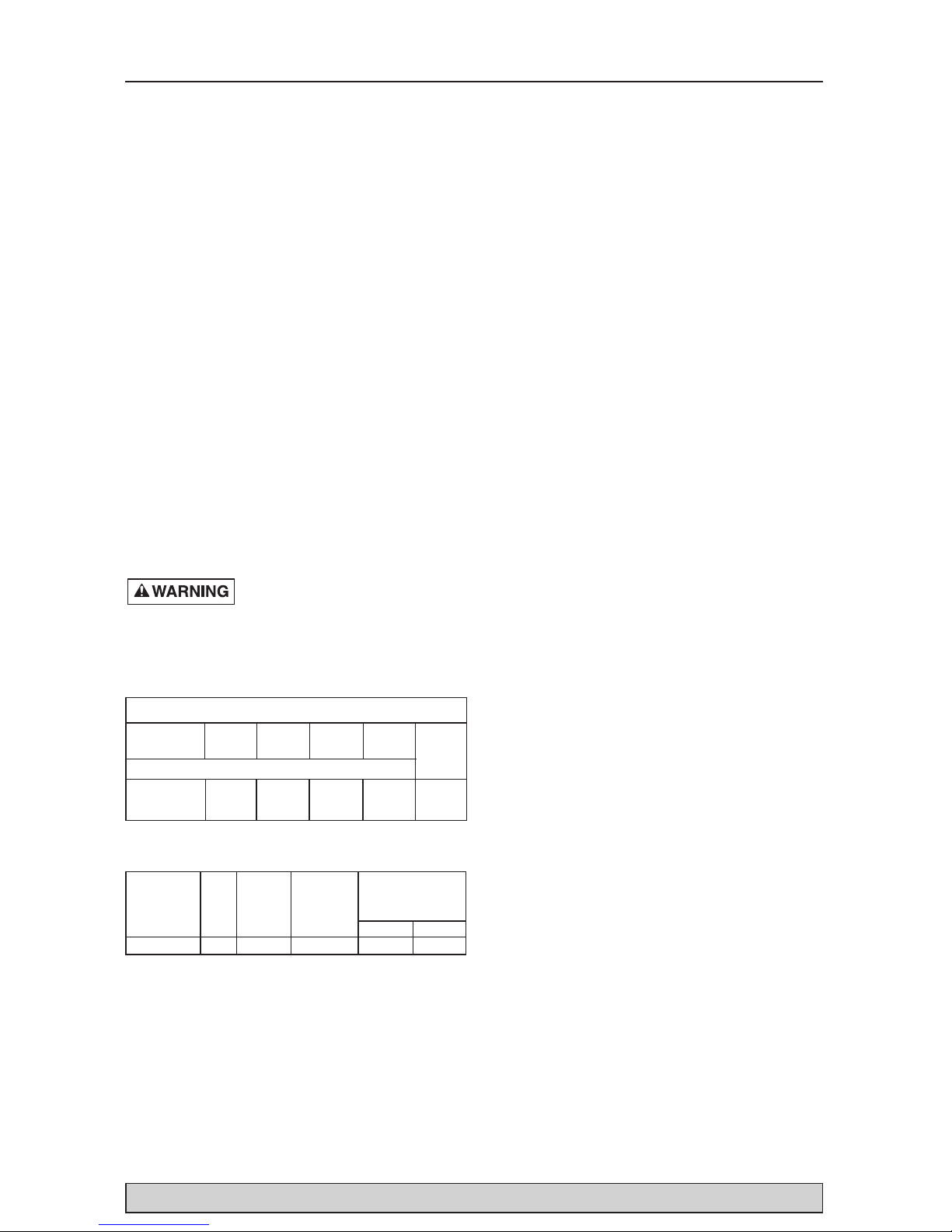
SPECIFICATIONS
Power supply required ...........................115V, 60 HZ.
Liquid Temp. Range ................32°F to 70°F(0°-21°C)
Individual Branch Circuit Required (min.) ....15 Amps
Discharge:
Check Valve.......................1-1/4" slip / 1-1/2" slip
Hose............................................................1-1/4"
NOTICE: Do not reduce size of discharge pipe or
hose below 1-1/4” diameter. If discharge is too
small, pump will overheat and fail prematurely.
NOTICE: This unit is not designed as a waterfall or
fountain pump, or for applications involving salt
water or brine! Use with waterfalls, fountains, salt
water or brine will void warranty.
Pump water only with this pump.
Do not use where water recirculates.
Not designed for use as a swimming pool drainer.
Risk of electrical shock. Do not
handle or plug in pump or pump motor with wet
hands or when standing on wet or damp surface or
in water.
PERFORMANCE
ELECTRICAL & SWITCH SPECIFICATIONS
GENERAL SAFETY INFORMATION
Electrically powered sump pumps normally give
many years of trouble-free service when correctly
installed, maintained, and used. However, unusual
circumstances (interruption of power to the pump,
dirt/debris in the sump, flooding that exceeds the
pump’s capacity, electrical or mechanical failure in
the pump, etc.) may prevent your pump from
functioning normally. To prevent possible water
damage due to flooding, consult your retailer about a
secondary AC sump pump, a DC backup sump
pump, and/or a high water alarm. See the
“Troubleshooting Chart” in this manual for
information about common sump pump problems
and remedies. For more information, see your
retailer or call customer service at
1-800-365-6832.
1. Know the pump application, limitations, and
potential hazards.
2. Do not use this pump in water with fish present. If
any oil leaks out of the motor it can kill fish.
3. Disconnect power before servicing.
4. Release all pressure within system before
servicing any component.
5. Drain all water from system before servicing.
6. Secure discharge line before starting pump. An
unsecured discharge line will whip, possibly
causing personal injury and/or property damage.
7. Check hoses for weak or worn condition before
each use, making certain that all connections are
secure.
8. Periodically inspect sump, pump and system
components. Keep free of debris and foreign
objects. Perform routine maintenance as
required.
9. Provide means of pressure relief for pumps whose
discharge line can be shut-off or obstructed.
10. Personal Safety:
a. Do not plug in or otherwise handle with wet
hands or when standing on wet or damp
surface, or in water.
b. Wear safety glasses at all times when working
with pumps.
c. Keep work area clean, uncluttered and
properly lighted – replace all unused tools
and equipment.
d. Keep visitors at a safe distance from work
area.
e. Make workshop child-proof – with padlocks,
master switches, and by removing starter
keys.
11. When wiring an electrically driven pump, follow
all electrical and safety codes that apply.
12. This equipment is only for use on 115 volt
(single phase) and is equipped with an
approved 3-conductor cord and 3-prong,
grounding-type plug.
TOTAL FEET (M) OF LIFT
51015
Series HP (1.5m) (3m) (4.6m)
CAPACITY GALLONS(L)/HOUR
FPRP3250C 1/2
3200 2700 2000 24 Ft.
(12 113) (10 220) (7 571) (7.3M)
No flow
at height
shown
below
Individual
Motor Branch *Switch Setting
Full Load Circuit in inches (mm)
Series HP Amps Req.(Amps) On Off
FPRP3250C 1/2 5.5 15 8"(203) 3.5"(89)

For parts or assistance, call Flotec Customer Service at 1-800-365-6832
Installation 3
To reduce risk of electric
shock, pull plug before
servicing. This pump has not been investigated
for use in swimming pool areas. Pump is
supplied with a grounding conductor and
grounding-type attachment plug. Be sure it is
connected only to a properly grounded
grounding-type receptacle.
Where a 2-prong wall receptacle is
encountered, it must be replaced with properly
grounded 3-prong receptacle installed in
accordance with codes and ordinances that
apply.
13. All wiring should be performed by a qualified
electrician.
14. Make certain power source conforms to
requirements of your equipment.
15. Protect electrical cord from sharp objects, hot
surfaces, oil, and chemicals. Avoid kinking cord.
Replace or repair damaged or worn cords
immediately.
16. Do not touch an operating motor. Modern motors
can operate at high temperatures.
17. Do not handle pump or pump motor with wet
hands or when standing on wet or damp surface,
or in water.
Hazardous voltage can shock,
burn or kill. If your basement
has water or moisture on floor, do not walk on wet
area until all power has been turned off. If shut-off
box is in basement, call electric company or hydro
authority to shut-off service to house, or call your
local fire department for instructions. Remove
pump and repair or replace. Failure to follow this
warning can result in fatal electrical shock.
Do not lift pump by power cord.
FOR EMERGENCY FLOODING
SITUATIONS
Hazardous voltage. Can shock,
burn or kill. If your basement has water or
moisture on floor, do not walk on wet area until all
power has been turned off. If shut-off box is in
basement, call electric company or hydro authority to
shut-off service to house, or call your local fire
department for instructions. Remove pump and
repair or replace. Failure to follow this warning can
result in fatal electrical shock.
1. Install the adapter and hose barb in the pump’s
check valve. Install the hose on the adapter and
clamp it.
2. Lift the cord and tape it to the pump’s discharge
pipe. Plug the pump and switch into a UL and/or
CSA approved type SJTW water resistant
3-prong grounding-type extension cord. The
cord must be at least #14 AWG and not more than
100 feet long. Plugs and extension cord must be
kept out of the water.
3. Remove the old pump from the sump and set it
aside.
4. Lower the pump into the sump. Make sure the
power cord is long enough that the plug is out of
the water when the pump is running.
5. Run the hose out of the flooded area to an
adequate drain area.
6. Risk of electrical shock.
Go to a dry area, remove wet
shoes and change wet clothing. WHEN YOU ARE
DRY, plug the extension cord into a grounded
electrical outlet (with a GFCI, if possible). DO
NOT STAND IN WATER TO PLUG IN THE PUMP.
7. National Electrical Code (NEC) and Canadian
Electrical Code (CEC) requirements prohibit the
use of an extension cord with this pump in a
permanent installation.
As soon as possible, remove the extension cord
and reinstall the pump as a permanent
replacement pump whose power cord connects
directly into a properly grounded grounding-type
receptacle. Install the pump in accordance with
the instructions, and in accordance with all codes
and ordinances that apply.
8. Monitor the pump’s operation. The pump will
automatically stop when the water level has
receded to the OFF point of the switch.
NOTE: The use of an extension cord is not CSA
approved with this pump.
INSTALLATION
1. Install pump in sump pit with minimum diameter
of 10" (254mm). Sump depth should be 10”
(254mm). Construct sump pit of tile, concrete,
steel or plastic. Check local codes for approved
materials and for proper installation.
2. Install pump in pit so that switch operating
mechanism has maximum possible clearance.
3. Pump should not be installed on clay, earth or
sand surfaces. Clean sump pit of small stones
and gravel which could clog pump. Keep pump
inlet screen clear.
NOTICE: Do not use ordinary pipe joint
compound on plastic pipe. Pipe joint compound
can attack plastics.
Risk of flooding. If the
flexible discharge hose is
used, make sure pump is secured in sump to
prevent movement. Failure to secure pump
may allow pump movement, switch
interference and prevent pump from starting or
stopping.
For parts or assistance, call Flotec Customer Service at 1-800-365-6832
4. Power Supply: Pump is designed for 115 V.,
60 Hz., operation and requires a minimum
15 amp individual branch circuit. Both pump and
switch are supplied with 3-wire cord sets with
grounding-type plugs. Switch plug is inserted
directly into outlet and pump plug inserts into
opposite end of switch plug.
Pump should always be
electrically grounded to a
suitable electrical ground such as a grounded
water pipe or a properly grounded metallic
raceway, or ground wire system. Do not cut off
round ground pin.
5. If pump discharge line is exposed to outside subfreezing atmosphere, portion of line exposed
must be installed so any water remaining in pipe
will drain to the outfall by gravity. Failure to do
this can cause water trapped in discharge to
freeze which could result in damage to pump.
6. After piping, check valve and float switch have
been installed, the unit is ready for operation.
7. Check the pump operation by filling sump with
water and observing pump operation through one
complete cycle. For switch settings see the Electrical
and Switch Specifications chart on Page 2.
Failure to make this
operational check may lead
to improper operation, premature failure, and
flooding.
OPERATION
Risk of electric shock. Do not
handle a pump or pump motor
with wet hands or when standing on wet or damp
surface, or in water.
1. Shaft seal depends on water for lubrication. Do
not operate pump unless it is submerged in
water as seal may be damaged if allowed to
run dry.
2. Motor is equipped with automatic reset thermal
protector. If temperature in motor should rise
unduly, switch will cut off all power before
Operation 4
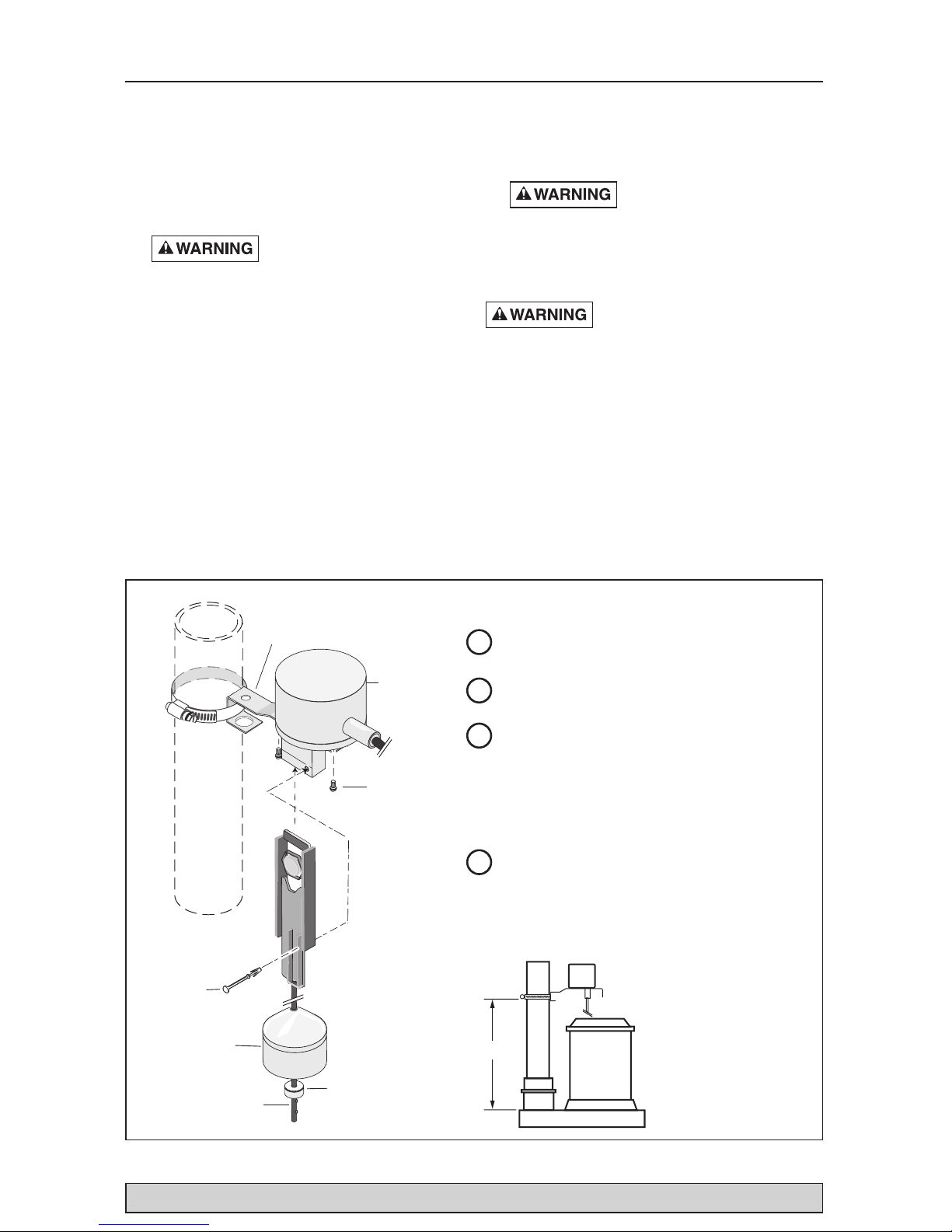
2
Slip the float and then the rod stop
onto the rod past the nib.
1
Mount the bracket on the switch
housing.
4
Attach the switch to the discharge pipe
as shown. The bottom of the bracket should
be 7-1/4” above the top of the volute for
correct on/off points (see below).
Vertical Switch Replacement
Rod
Rod Stop
Float
Bracket
Bracket
Mounting
Screws
Switch
Housing
Pin
3
Insert the rod assembly up into the
switch housing and lock into place
with the pin.
NOTICE: Be sure the pin holds the
rod in the switch housing or the pump
will not shut off.
7-1/4”
NOTICE: See instructions included with replacement switch, Part Number FPS17-66.

For parts or assistance, call Flotec Customer Service at 1-800-365-6832
Operation / Troubleshooting 5
SYMPTOM PROBABLE CAUSE(S) CORRECTIVE ACTION
Pump won’t start or run. Pump is not plugged in. Check and see if pump is plugged in to a proper outlet.
Blown fuse or tripped breaker. If blown, replace with fuse of proper size. If tripped, reset
breaker.
Low line voltage. If voltage under recommended minimum, check size of wiring
from main switch on property. If OK, contact power company
or hydro authority.
Defective motor. Replace pump.
Defective float switch. Replace float switch.
Impeller. If impeller won’t turn, remove lower pump body and locate
source of binding.
Float obstructed. Remove obstruction.
Pump starts and stops Backflow of water from piping. Install or replace check-valve.
too often.
Faulty float switch. Replace float switch.
Pump won’t shut off. Defective float switch. Replace float switch.
Restricted discharge Remove pump and clean pump and piping.
(obstacle or ice in piping).
Float obstructed. Remove obstruction.
Restricted intake screen. Remove the pump and clean the intake screen and the
impeller.
Pump operates but Low line voltage. If voltage under recommended minimum, check size of wiring
delivers little or no water. from main switch on property. If OK, contact power company
or hydro authority.
Something caught in impeller. Remove the pump and clean out the impeller.
Worn or defective parts or Clean impeller if plugged; otherwise replace pump.
plugged impeller.
Vent hole plugged. Use a nail or paperclip to open vent hole in discharge pipe.
Restricted intake screen. Remove the pump and clean out the intake screen.
Check valve is installed either Be sure check valve is installed correctly.
backward or upside down.
TROUBLESHOOTING CHART
damage can be done to motor. When motor has
cooled sufficiently, switch will reset automatically
and restart motor. If protector trips repeatedly,
pump should be removed and checked as to
cause of difficulty. Low voltage, long extension
cords, clogged impeller, very low head or lift, or
a plugged or frozen discharge pipe, etc., could
cause cycling.
3. Pump will not remove all water. If operating a
pump manually, and suddenly no water comes
out of the discharge hose, shut off the unit
immediately. The water level is probably very low
and the unit is no longer primed.
Risk of electric shock. Before
attempting to check why unit
has stopped operating, disconnect power from
unit.
For parts or assistance, call Flotec Customer Service at 1-800-365-6832
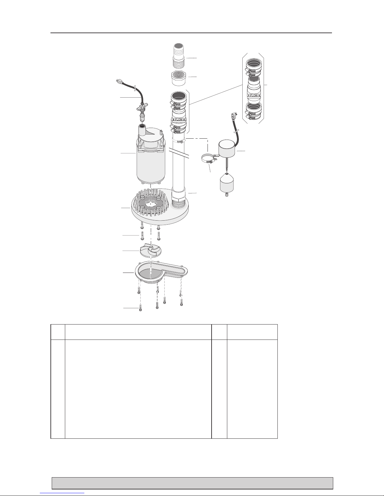
Repair Parts 6
7
6
5
4
2
1
3
10
11
12
8
13
9
6131 1209
**If motor fails, replace entire pump.
† Standard hardware item; purchase locally.
• Not illustrated
Key
No. Part Description Qty.
1 Power Cord Assembly 1 PS117-54-TSU
2 Motor 1 **
3 Volute (Upper) 1 PS1-31P
4 Screw, #8-32x5/8” Phillips Pan Head 4 †
5 Impeller 1 RP0000911A
6 Volute (Lower) 1 PS1-30P
7 Screw, #8-16x1/2” Lg. Pan Head 7 †
8 1-1/4” NPT x 1-1/4” Slip Adapter 1 †
9 Switch Clamp 1 †
10 Vertical Float Switch Assembly (includes Key No. 9) 1 FPS17-66
11 Check Valve 1 FP0026-10
12 1-1/2” Slip x 1-1/4” NPT Adapter 1 †
13 1-1/4” NPT x 1-1/4” Hose Barb 1 †
• 1-1/4” x 24’ Hose Kit (includes Key No. 13) 1 FP0012-6U
 Loading...