

Flotec E50TLT, E50VLT, E75VLT Owner's Manual

OWNER’S MANUAL
Submersible Sump Pumps
NOTICE D’UTILISATION
Pompes submersibles
pour puisard
MANUAL DEL USUARIO
Bombas sumergibles
para sumideros
Installation/Operation/Parts
For further operating,
installation, or maintenance
assistance:
Call 1-800-365-6832
English ....................... Pages 2-9
Installation/Fonctionnement/Pièces
Pour plus de renseignements
concernant l’utilisation,
l’installation ou l’entretien,
Composer le 1 (800) 365-6832
Français ............... Pages 10-17
Instalación/Operación/Piezas
Para mayor información sobre el
funcionamiento, instalación o
mantenimiento de la bomba:
Llame al 1-800-365-6832
Español .................Paginas 18-25
© 2012 FP877 (06/05/12)
293 Wright Street, Delavan, WI 53115
Phone: 1-800-365-6832
Fax: 1-800-526-3757
Web Site: flotecwater.com
6201 0410
E50TLT E50VLT
E75VLT

Safety 2
For parts or assistance, call Flotec Customer Service at 1-800-365-6832
General Safety Information
Your automatic sump pump should give years
of trouble-free service when correctly installed,
maintained, and used. However, interruption
of power to the pump, dirt/debris in the sump,
flooding that exceeds the pump’s capacity,
electrical or mechanical failure in the pump,
etc., may prevent normal pump operation. To
help prevent damage from flooding, purchase
a secondary AC sump pump, a DC backup
sump pump, and/or a high water alarm. See
Troubleshooting in this manual for information
about common sump pump problems and
remedies. For more information, call Flotec
customer service at 1-800-365-6832 or visit our
website at FlotecWater.com.
Risk of electric shock. Can shock,
burn or kill. To reduce the risk of hazardous
or fatal electrical shock, follow instructions A
through D, below:
A.
This pump has an approved 3-conductor
power cord with 3-prong, grounding-type plug.
Connect the pump only to a properly grounded,
3-prong outlet. If the sump pump circuit has
a 2-prong outlet, replace it with a grounded
3-prong outlet installed according to code.
B. Unplug the pump before handling or servicing
it. If your basement floor is wet, turn off all
power before walking on it. If the shut-off box
is in the basement, call your electric company
or hydro authority to shut off service to the
house, or call your local fire department
for instructions. After turning off the power,
remove the pump for service.
C. Protect the electrical cords from sharp objects,
hot surfaces, oil, and chemicals. Avoid kinking
the cords. Replace damaged or worn cords.
D. Do not lift the pump by the power cord.
Risk of fire. Plastic pipe glue
is extremely flammable. Follow the glue
manufacturer’s instructions when assembling
glued plastic pipe.
Risk of burns. Motors may run hot.
Allow 20 minutes to cool before handling.
1. Know the pump application, limitations, and
potential hazards.
2. Do not use this pump in water with fish
present. If any oil leaks out of the motor it can
kill fish.
3.
Drain the system completely before servicing it.
4. To prevent a flexible discharge line from
whipping, which could cause injury or
damage, fasten it down before starting
thepump.
5. Before each use, check any hoses in the system
for weakness or wear. Make certain that all
connections are tight.
6. Periodically inspect the sump, the pump,
and the piping for debris and foreign objects.
Perform routine cleaning as required.
7. Personal Safety:
a. Wear safety glasses at all times when
working with pumps.
b. Keep your work area clean, uncluttered
and properly lighted; put away all unused
tools and equipment.
c. Keep visitors at a safe distance from the
workarea.
d. Make workshop child-proof with padlocks
and master switches. Remove any
starterkeys.
8. This pump installation must meet all applicable
laws, codes, and ordinances.
California Proposition 65 Warning
This product and related
accessories contain chemicals known to the
State of California to cause cancer, birth defects
or other reproductive harm.
Specifications
Power supply ..................... 115V, 60 HZ., 15 Amp Circuit
Liquid Temp. Range ......................... 32°F to 70°F(0°-21°C)
Individual Branch Circuit Required (min.) ............15 Amps
Discharge: ............................................1-1/2” Female NPT
This pump is designed for use in a residential
sump only. Pump water only with this pump.
NOTICE: This unit is not designed as a waterfall
or fountain pump, or for applications involving
salt water or brine! Use with waterfalls,
fountains, salt water or brine will void warranty.
Do not use where water recirculates.
Not designed for use as a swimming pool
drainer.
NOTICE: Read this owner’s manual for
installation, operation, and safety information.
Tools Required:
Pipe wrench, Strap Wrench, or Slip-Joint Pliers,
Hacksaw,
Screw Driver,
File or Sandpaper
Materials Required:
1-1/2” ABS or PVC Pipe with Cement to match
Threaded Adapter (Pipe to Pump)
Check Valve – Purchase a FP0026-10 (goes
in the discharge line) or FP0026-6D (goes in
the pump discharge). If your check valve does
not have an 1/8” anti-airlock hole, drill one in
the discharge pipe
just above where it screws
into the pump discharge
. Be sure to install the
check valve so that the flow will be away from
thepump.
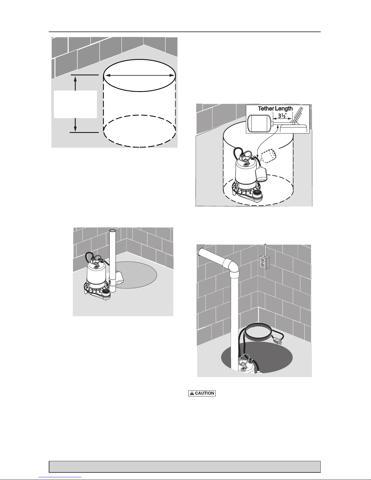
1A. Minimum sump size: 10” (254mm) diameter
by 10” (254mm) depth for vertical switch
models; 14” (356mm) diameter by 18”
(457mm) depth for tethered switch models.
1B. Construct the sump pit of tile, concrete, steel,
or plastic; it must meet code requirements.
1C. No clay, earth, sand, or gravel in the sump
(they will clog the pump). Keep the pump inlet
screen clear.
2A. Install the discharge plumbing and check
valve, using PTFE pipe thread sealant tape NOT pipe jointcompound.
2B. Tighten the pipe into the pump (hand tight
+1-1/2 turns).
2C. Install a check valve in the vertical pipe to
prevent flow backwards through the pump
when it shuts off. To prevent airlocking the
pump, drill a 1/8” (3.2 mm) hole in the
discharge pipe just above where it screws into
the pump discharge. Install the check valve
above this hole, but keep it as close to the
pump as possible. Be sure the hole is below
the waterline and below the check valve.
2D. To reduce noise and vibration, cut the
discharge pipe near the pump and fasten
a short length of rubber hose (1-7/8” (48
mm) I.D., e.g. radiator hose) into it with
hoseclamps.
3. Place the pump in the sump; make sure that
nothing interferes with switch operation. For
tethered switch models, the tether length
should be 3-1/2” (See Figure 3).
4. Finish installing the necessary plumbing.
Follow the glue manufacturer’s instructions for
safety precautions and curing time.
Risk of flooding. Make sure the pump
cannot move in the sump. If the pump moves
when it runs, the piping or sump wall may
interfere with the switch and prevent the pump
from starting or stopping.
Installation 3
For parts or assistance, call Flotec Customer Service at 1-800-365-6832
Hard Surface –
No Sand, Clay,
Gravel
Sump Pit
14" Minimum
with Tethered Switch
10" Minimum
with Vertical Switch
10" Min. with
Vertical Switch
18" Min. with
Tethered Switch
Figure 1
6201 0410
Figure 2
Figure 4
Figure 3
 Loading...