

Flotec AT250701, AT251001, AT251501 Owner's Manual

OWNER’S MANUAL
Centrifugal Pumps
with Integral Trap
NOTICE D’UTILISATION
Pompes centrifuges
à filtre collecteur intégré
MANUAL DEL USUARIO
Bombas centrífugas
con colector integral
Installation/Operation/Parts
For further operating, installation,
or maintenance assistance:
Call 1-800-365-6832
English . . . . . . . . . . . . . Pages 2-12
Installation/Fonctionnement/Pièces
Pour plus de renseignements
concernant l’utilisation,
l’installation ou l’entretien,
Composer le
1 (800) 365-6832
Français . . . . . . . . . . Pages 13-23
Instalación/Operación/Piezas
Para mayor información sobre el
funcionamiento, instalación o
mantenimiento de la bomba:
Llame al 1-800-365-6832
Español . . . . . . . . . .Paginas 24-34
©2002 PRINTED IN U.S.A. FP243 (Rev. 12/6/02)
Mod. AT250701,
AT251001, AT251501
P.O. Box 342, Delavan, WI 53115
Phone: 1-800-365-6832
Fax: 1-800-526-3757
E-Mail: info@flotecwater.com
Web Site: http://www.flotecwater.com
®

Safety 2
For parts or assistance, call Flotec Customer Service at 1-800-365-6832
FLOTEC CENTRIFUGAL PUMP
WITH INTEGRAL TRAP
To avoid unneeded service calls, prevent possible
injuries, and get the most out of your pump, READ THIS
MANUAL CAREFULLY!
The Flotec Self-priming Centrifugal Pump:
• Is designed for use with swimming pools or as a
centrifugal pump.
• Is an excellent performer; durable, reliable.
IMPORTANT SAFETY
INSTRUCTIONS
Always follow basic safety precautions with this
equipment, including the following.
To reduce the risk of injury, do not permit children to use this product unless they are closely
supervised at all times.
This pump is for use with permanently
installed pools and may also be used with hot tubs
and spas if so marked. Do not use with storable pools.
A permanently installed pool is constructed in or on
the ground or in a building such that it cannot be
readily disassembled for storage. A storable pool is
constructed so that it may be readily disassembled for
storage and reassembled to its original integrity.
SAVE THESE INSTRUCTIONS
READ AND FOLLOW
SAFETY INSTRUCTIONS!
This is the safety alert symbol. When you see this
symbol on your pump or in this manual, look for
one of the following signal words and be alert to the
potential for personal injury.
warns about hazards that will cause serious
personal injury, death or major property damage if
ignored.
warns about hazards that can cause serious
personal injury, death or major property damage if
ignored.
warns about hazards that will or can cause
minor personal injury or property damage if ignored.
The label NOTICE indicates special instructions which
are important but not related to hazards.
Carefully read and follow all safety instructions in this
manual and on equipment. Keep safety labels in good
condition; replace if missing or damaged.
Incorrectly installed or tested equipment
may fail, causing severe injury or property
damage.
Read and follow instructions in owner's
manual when installing and operating equipment. Have
a trained pool professional perform all pressure tests.
1. Do not connect system to a high pressure or city
water system.
2. Use equipment only in a pool or spa installation.
3. Trapped air in system can cause explosion. BE SURE
all air is out of system before operating or testing
equipment. Do not use compressed air to clean, test,
or purge equipment for winter.
Before pressure testing, make the following safety
checks:
• Check all clamps, bolts, lids, and system accessories
before testing.
• Release all air in system before testing.
•Tighten Flotec trap lids to 30 ft. lbs. (4.1 kg-m) torque
for testing.
•Water pressure for test must be less than 25 PSI (7.5
kg/cm
2
).
•Water Temperature for test must be less than 100° F
(38° C).
• Limit test to 24 hours. After test, visually check sys-
tem to be sure it is ready for operation. Remove trap
lid and retighten hand tight only.
NOTICE: These parameters apply to Flotec equipment
only. For non-Flotec equipment, consult manufacturer.

For parts or assistance, call Flotec Customer Service at 1-800-365-6832
Ta b le of Contents 3
AT TACH ORIGINAL RECEIPT HERE FOR WARRANTY CONSIDERATION.
FLOTEC warrants to the original consumer purchaser (“Purchaser”) of its products that they are free from defects in material or workmanship.
If within twelve (12) months from the date of the original consumer purchase
any such product shall prove to be defective, it shall be repaired or replaced at
FLOTEC’s option, subject to the terms and conditions set forth below. Your original receipt of purchase is required to determine warranty eligibility.
Exceptions to the Twelve (12) Month Warranty
Ninety (90) Day Warranty:
If within ninety (90) days from original consumer purchase any Drill Pump,
Pitcher Pump, or In-Line Water Filter Cartridge shall prove to be defective, it
shall be replaced, subject to the terms set forth below.
Two (2) Year Warranty:
If within two (2) years from original consumer purchase any 1/3 HP Submersible
Sump Pump or Model FP2800DCC shall prove to be defective, it shall be
repaired or replaced at FLOTEC’s option, subject to the terms and conditions set
forth below.
Three (3) Year Warranty:
If within three (3) years from original consumer purchase any 4” Submersible
Well Pump, or 1/2 HP Submersible Sump Pump, shall prove to be defective, it
shall be repaired or replaced at FLOTEC’s option, subject to the terms and conditions set forth below.
Five (5) Year Warranty:
If within five (5) years from original consumer purchase any Pre-Charge water
system tank shall prove to be defective, it shall be repaired or replaced at
FLOTEC’s option, subject to the terms and conditions set forth below.
General Terms and Conditions
Purchaser must pay all labor and shipping charges necessary to replace product
covered by this warranty. This warranty shall not apply to acts of God, nor shall
it apply to products which, in the sole judgement of FLOTEC, have been subject to negligence, abuse, accident, misapplication, tampering, alteration; nor
due to improper installation, operation, maintenance or storage; nor to other
than normal application, use or service, including but not limited to, operational failures caused by corrosion, rust or other foreign materials in the system,
or operation at pressures in excess of recommended maximums.
Requests for service under this warranty shall be made by returning the defective product to the Retail outlet or to FLOTEC as soon as possible after the discovery of any alleged defect. FLOTEC will subsequently take corrective action
as promptly as reasonably possible. No requests for service under this warranty will be accepted if received more than 30 days after the term of the warranty.
This warranty sets forth FLOTEC’s sole obligation and purchaser’s exclusive
remedy for defective products.
FLOTEC SHALL NOT BE LIABLE FOR ANY CONSEQUENTIAL, INCIDENTAL,
OR CONTINGENT DAMAGES WHATSOEVER.
THE FOREGOING WARRANTIES ARE EXCLUSIVE AND IN LIEU OF ALL
OTHER EXPRESS WARRANTIES. IMPLIED WARRANTIES, INCLUDING BUT
NOT LIMITED TO THE IMPLIED WARRANTIES OF MERCHANTABILITY AND
FITNESS FOR A PARTICULAR PURPOSE, SHALL NOT EXTEND BEYOND THE
DURATION OF THE APPLICABLE EXPRESS WARRANTIES PROVIDED HEREIN.
Some states do not allow the exclusion or limitation of incidental or consequential damages or limitations on how long an implied warranty lasts, so the
above limitations or exclusions may not apply to you. This warranty gives you
specific legal rights and you may also have other rights which vary from state
to state.
Flotec Limited Warranty
FLOTEC • P.O. Box 342 • Delavan, WI U.S.A. 53115
Phone: 1-800-365-6832 • Fax: 1-800-526-3757
E-Mail: info@flotecwater.com • Web Site: http://www.flotecwater.com
Thank you for purchasing a top quality, factory tested pump.
Page
General Safety .....................................................................................................2
Warranty..............................................................................................................3
Installation ........................................................................................................4,5
Electrial.............................................................................................................6,7
Operation ........................................................................................................8, 9
Pump Service..................................................................................................9,10
Troubleshooting..................................................................................................11
Repair Parts .......................................................................................................12
Installation 4
For parts or assistance, call Flotec Customer Service at 1-800-365-6832
NOTICE: Port threads are: Internal - 2" NPT for direct
connection to pipe. External - 3-1/4" Buttress.
For quick disconnect pipe connections, use the 1-1/2” Slip
Half Union Kit included with the pump.
Only qualified, licensed personnel should install pump
and wiring.
Pump mount must:
Be located away from corrosive or flammable liquids.
Have enough ventilation to maintain air temperature at
less than the maximum ambient temperature rating (Max.
Amb.) listed on the motor model plate. If this pump is
installed in an enclosure/pump house, the enclosure
must have adequate ventilation and air circulation to
keep the temperature in the enclosure at or below the
motor’s rated ambient temperature whenever the pump is
running.
Be solid - Level - Rigid - Vibration free. (To reduce vibration and pipe stress, bolt pump to mount.)
Allow pump suction inlet height to be as close to water
level as possible. Pump will not lift water more than
10'(3m).
Allow use of short, direct suction pipe (To reduce friction
losses).
Allow for gate valves in suction and discharge piping.
Have adequate floor drainage to prevent flooding.
Be protected from excess moisture.
Allow adequate access for servicing pump and piping.
Fire and burn hazard. Modern motors run at
high temperatures. To reduce the risk of fire, do not allow
leaves, debris, or foreign matter to collect around the
pump motor. To avoid burns when handling the motor, let
it cool for 20 minutes before trying to work on it.
NOTICE: When connecting threaded pipe directly to
pump, use Teflon tape or Plasto-Joint Stik1to seal connections. Do not use pipe dope; pipe dope causes cracking in some plastics and may damage components in
piping system.
When connecting pipe to pump with union half, use
Teflon tape or Plasto-Joint Stik1between pipe and union
adapter. Union collar to pump should be assembled dry
and hand-tight.
NOTICE: Pump suction and discharge connections have
molded in thread stops. DO NOT try to screw pipe in
beyond these stops.
Teflon Taping Instructions:
Use only new or clean PVC pipe fittings.
Wrap male pipe threads with one to two layers of Teflon
tape. Cover entire threaded portion of pipe.
Do not overtighten or tighten past thread stop in pump
port!
If leaks occur, remove pipe, clean off old tape, rewrap
with one to two additional layers of tape and remake the
connection.
NOTICE: Support all piping connected with pump!
Piping:
Use at least 1-1/2" (38mm) pipe (use 2"(51mm) pipe if
possible). Increase size if a long run is needed. When
using 1-1/2" pipe, connect to pump with 1-1/2" to 2" (38
to 51mm) reducing adapter (included).
To avoid strains on the pump, support both suction and
discharge pipes independently. Place these supports near
the pump.
To avoid a strain left by a gap at the last connection, start
all piping at the pump and run pipe away from the
pump.
To avoid airlocking, slope suction pipe slightly upward
toward the pump.
NOTICE: To prevent flooding when removing pump for
service, all flooded suction systems must have gate
valves in suction and discharge pipes.
1
Lake Chemical Co., Chicago, Illinois
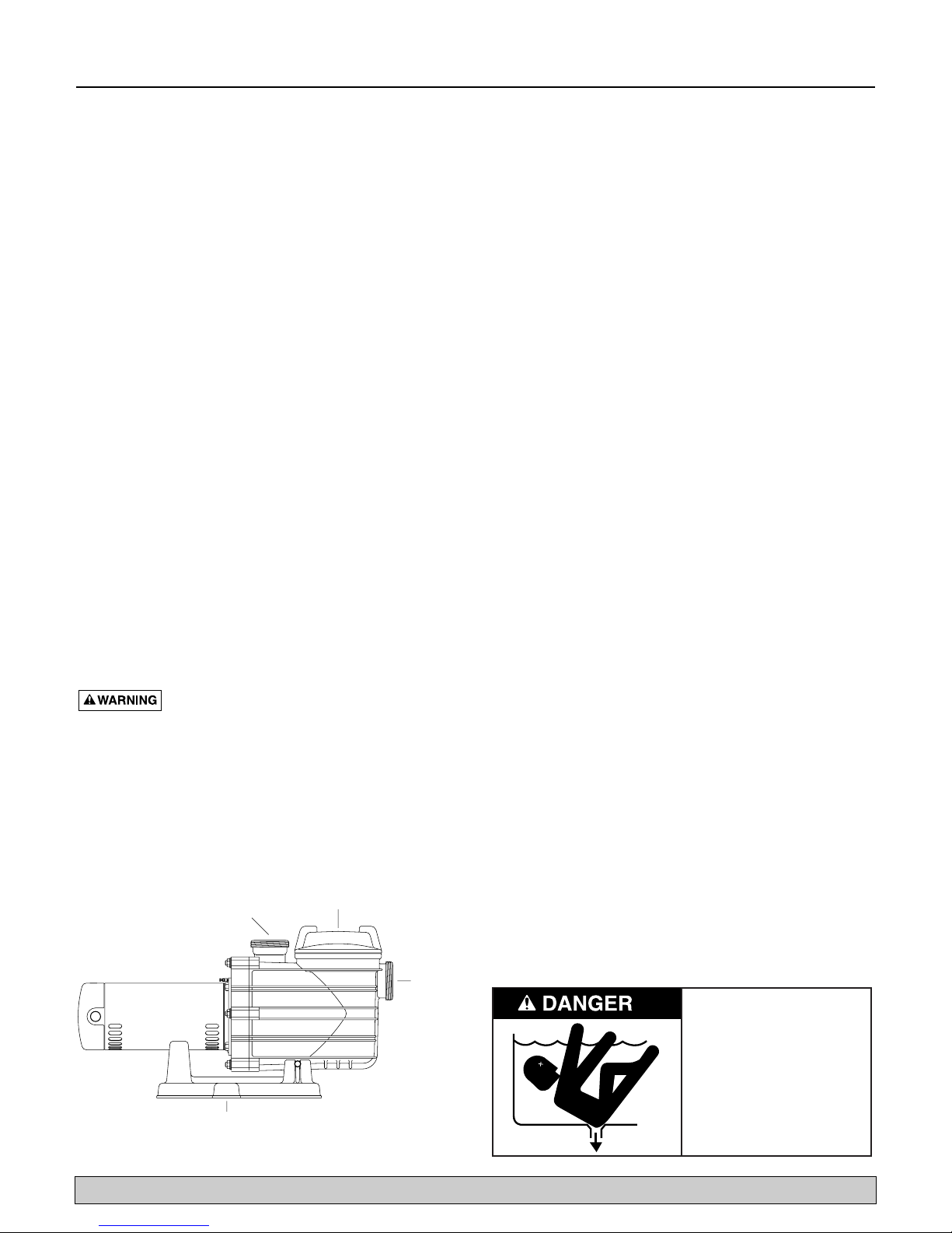
POOL PUMP SUCTION REQUIREMENTS
Figure 1
STRAINER BASKET
DISCHARGE PORT
TO FILTER OR POOL
COVER
PUMP MAY BE BOLTED TO LEVEL
FOUNDATION OR MOUNTING BRACKET
SUCTION
PORT
FROM
POOL
OR
VACUUM
FILTERS
037 0893
Hazardous Suction.
Can trap hair or body,
causing severe injury
or death.
• Do not block suction.
• Keep small children
under close adult
supervision at all times.

Installation 5
For parts or assistance, call Flotec Customer Service at 1-800-365-6832
Pump suction is hazardous and can trap and
drown or disembowel bathers. Do not use or operate swimming pools, spas, or hot tubs if a suction outlet
cover is missing, broken, or loose. Follow the guidelines
below for a pump installation which minimizes risk to
users of pools, spas, and hot tubs.
Entrapment Protection
The pump suction system must provide protection
against the hazard of suction entrapment or hair entrapment/entanglement.
Suction Outlet Covers
All suction outlet covers must be maintained. They must
be replaced if cracked, broken, or missing.
See “Testing and Certification”, at right, for outlet cover
certification requirements.
All suction outlets must have correctly installed, screwfastened covers in place.
Suction Outlets Per Pump (Figure 2, below)
Provide at least two hydraulically balanced main drains,
with covers, as suction outlets for each circulating pump
suction line. The centers of the main drains (suction outlets)
on any one suction line must be at least three feet apart.
The system must be built so that it cannot operate with
the pump drawing water from only one main drain (that
is, there must be at least two main drains connected to
the pump whenever it is running – see Figure 2, below).
However, if two main drains run into a single suction
line, the single suction line may be equipped with a
valve which will shut off both main drains from the
pump (see Figure 2).
More than one pump can be connected to a single suction line as long as the requirements above are met.
Water Velocity
The maximum water velocity through the suction fitting
or cover for any suction outlet must be 1.5 feet per second unless the outlet complies with the latest
ASME/ANSI Specification for Suction Fittings For Use in
Swimming Pools, Spas, Hot Tubs, and Whirlpool Bathtub
Applications. In any case, do not exceed the suction fit-
ting’s maximum designed flow rate.
If 100% of the pump’s flow comes from the main drain
system, the maximum water velocity in the pump suction
hydraulic system must be six feet per second or less even
if one main drain (suction outlet) is completely blocked.
The flow through the remaining main drain(s) must comply with the latest ASME/ANSI Specification for Suction
Fittings For Use in Swimming Pools, Spas, Hot Tubs, and
Whirlpool Bathtub Applications.
Testing and Certification
Suction outlet covers must have been tested by a nationally recognized testing laboratory and found to comply
with the latest ASME/ANSI Specifications for Suction
Fittings For Use in Swimming Pools, Spas, Hot Tubs, and
Whirlpool Bathtub Applications.
Fittings:
Fittings restrict flow; for best efficiency use fewest possible fittings (but at least two suction outlets).
Avoid fittings which could cause an air trap.
Pool fittings must conform to International Association of
Plumbing and Mechanical Officials (IAPMO) standards.
Use only non-entrapping suction fitting or double suction.
Figure 2 – Recommended pump suction layout.
IAPMO Certified
Anti-entrapment
Cover or Suction Fitting,
screw-fastened to
Main Drain Sump
Suction Outlet
(Main Drain)
Valves OK between
pump and Tee
At Least
3 Feet
No valves between
Tee and Main Drains
IAPMO Certified
Anti-entrapment
Cover or Suction Fitting,
screw-fastened to
Main Drain Sump
Suction Outlet
(Main Drain)
Pump
2762 0197
Electrical 6
For parts or assistance, call Flotec Customer Service at 1-800-365-6832
Hazardous voltage. Can shock, burn,
or cause death. Ground pump before connecting to
power supply.
Ground motor before connecting to electrical
power supply. Failure to ground motor can cause
severe or fatal electrical shock hazard.
Do not ground to a gas supply line.
To avoid dangerous or fatal electrical shock, turn
OFF power to motor before working on electrical
connections.
Ground Fault Circuit Interrupter (GFCI) tripping
indicates an electrical problem. If GFCI trips and
will not reset, have a qualified electrician inspect and
repair electrical system.
Exactly match supply voltage to nameplate volt-
age. Incorrect voltage can cause fire or seriously
damage motor and voids warranty. If in doubt consult a
licensed electrician.
Voltage
Voltage at motor must be not more than 10% above or
below motor nameplate rated voltage or motor may
overheat, causing overload tripping and reduced component life. If voltage is less than 90% or more than 110%
of rated voltage when motor is running at full load, consult power company.
Grounding/Bonding
Install, ground, bond and wire motor according to local
or National Electrical Code requirements.
Permanently ground motor. Use green ground terminal
provided under motor canopy or access plate (See Figure
3); use size and type wire required by code. Connect
motor ground terminal to electrical service ground.
Bond motor to pool structure. Use a solid copper conductor, size No. 8 AWG (8.4 sq.mm) or larger. Run wire
from external bonding lug (see Figure 3) to reinforcing
rod or mesh.
Connect a No. 8 AWG (8.4 sq.mm) solid copper bonding
wire to the pressure wire connector provided on the
motor housing and to all metal parts of the swimming
pool, spa, or hot tub and to all electrical equipment,
metal piping or conduit within 5 feet (1.5 m) of the
inside walls of swimming pool, spa, or hot tub.
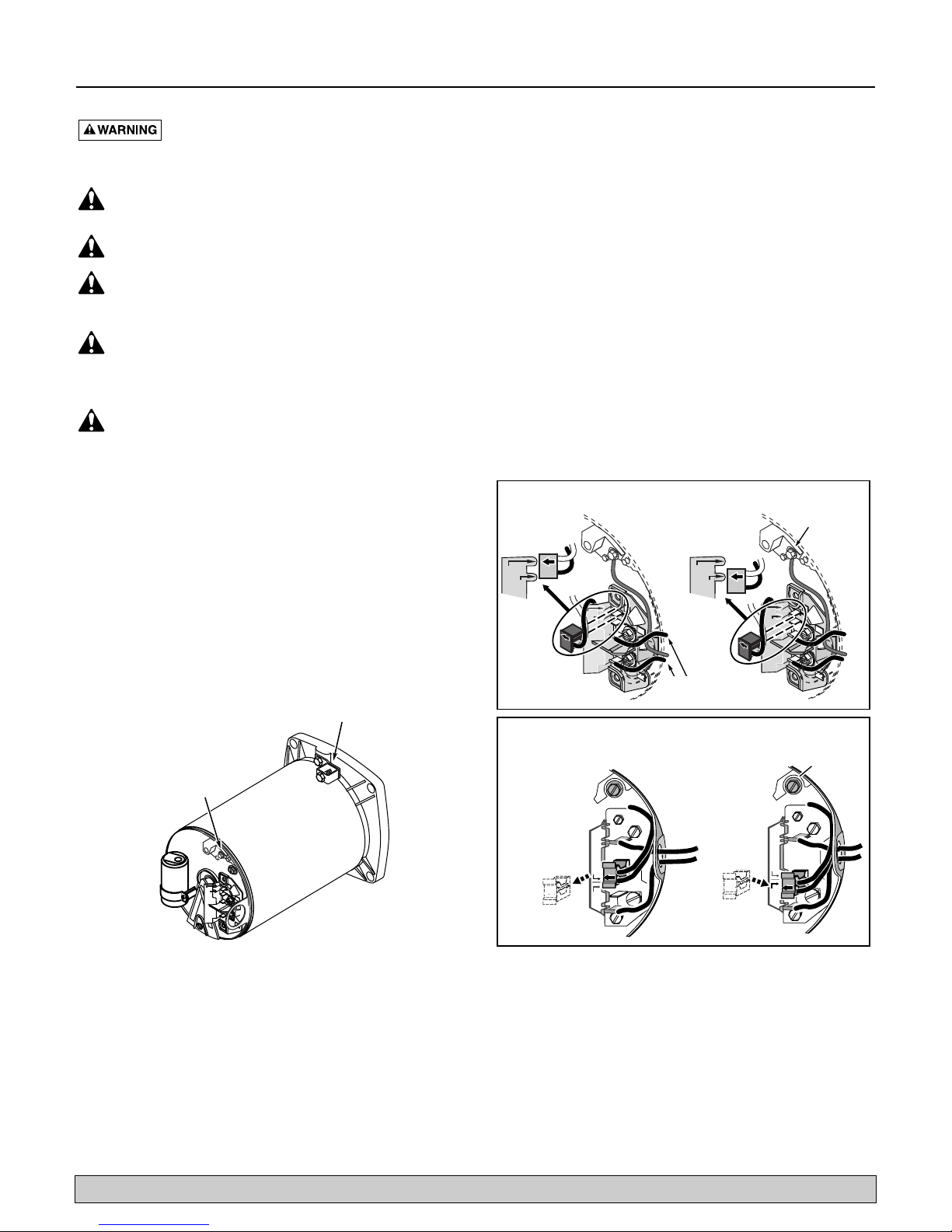
Figure 3 – Typical ground screw and bonding lug
locations.
Figure 4 – Wiring hook-up diagram, 115/230V dual
voltage.
230 Volt to 115 Volt Conversion. Move plug to change voltage.
Ground
Screw
230 V
230V
115V
230V
115V
A
A
L2
L2
115 V
230V
115V
230V
115V
A
A
L2
L2
Bonding
Lug
Green
Ground
Screw
A
A
230V
115V
L2
L2
L1
L1
L1
L1
L1
Power Supply
L1
Wires
230 Volt to 115 Volt Conversion. Move plug to change voltage.
Pull plug
1.
straight
out from
terminal
board.
1.
230
Volts
115
Volts
2.
Plug in again
with arrow
on plug
Ground
Screw
pointing to
'115 Volts'.
230
Volts
A
L1
2.
A
115
Volts
L1
3962 0401 A

Electrical 7
For parts or assistance, call Flotec Customer Service at 1-800-365-6832
Wiring
Pump must be permanently connected to circuit. Table I,
below, gives correct wire and circuit breaker sizes for the
pump alone. If other lights or appliances are also on the
same circuit, be sure to add their amp loads to pump
amp load before figuring wire and circuit breaker sizes.
(If unsure how to do this or if this is confusing, consult a
licensed electrician.) Use the load circuit breaker as the
master on-off switch.
Install a Ground Fault Circuit Interrupter (GFCI) in circuit; it will sense a short-circuit to ground and disconnect power before it becomes dangerous to pool users.
For size of GFCI required and test procedures, see GFCI
manufacturer’s instruction.
In case of power outage, check GFCI for tripping (which
will prevent normal pump operation). Reset if necessary.
NOTICE: If you do not use conduit when wiring motor,
be sure to seal wire opening on end of motor to prevent
dirt, bugs, etc., from entering.
TABLE I - RECOMMENDED FUSING DATA
Serv. to Motor - Dist. in Ft. (M)
Motor Branch Fuse Max Load Voltage/ 0-100' 101-200' 201-300'
HP Rating Amps* Amps Hz/Phase (0-30) (30-60) (60-90)
3/4 15 9.9 115/60/1 14(2) 10(5.5) 10(5.5)
12013.4 115/60/1 12(3) 10(5.5) 8(8.4)
1-1/2 20 15.3 115/60/1 12(3) 8(8.4) 6(14)
3/4 15 5.0 230/60/1 14(2) 14(2) 14(2)
1156.7 230/60/1 14(2) 14(2) 14(2)
1-1/2 15 7.6 230/60/1 14(2) 14(2) 14(2)
* Time delay fuses are recommended instead of standard fuses in any motor circuit.
AWG
Wire
Size
(mm2)
}
Operation 8
For parts or assistance, call Flotec Customer Service at 1-800-365-6832
NOTICE: NEVER run pump dry. Running pump dry may
damage seals, causing leakage and flooding. Fill pump
with water before starting motor.
Before removing trap cover:
1. STOP PUMP before proceeding.
2. CLOSE GATE VALVES in suction and discharge pipes.
3. RELEASE ALL PRESSURE from pump and piping
system.
If pump is being pressure tested, be sure pressure
has been released before removing trap cover.
Fire and burn hazard. Modern motors run
at high temperatures. To reduce the risk of fire, do not
allow leaves, debris, or foreign matter to collect around
the pump motor. To avoid burns when handling the
motor, let it cool for 20 minutes before trying to work on
it. An automatic internal cutoff switch protects the motor
from heat damage during operation.
Priming Pump
Release all pressure from filter, pump, and piping system;
see the filter owner’s manual.
In a flooded suction system (water source higher than
pump), pump will prime itself when suction and discharge valves are opened.
If pump is not in a flooded suction system, unscrew and
remove trap cover (see Figure 5); fill trap and pump with
water.
Do not lubricate the trap cover O-Ring. The original
equipment O-Ring contains a permanent internal
lubricant.
NOTICE: If you replace the O-Ring with a non-internally lubricated O-Ring, you may need to apply a silicone
based lubricant.
Clean and inspect O-Ring; reinstall on trap cover.
Replace trap cover on trap; turn clockwise to tighten
cover.
NOTICE: Tighten trap cover by hand only (no wrenches)!
Pump should prime now. Priming time will depend on
vertical length of suction lift and horizontal length of
suction piping.
If pump does not prime, make sure that all valves are
open, suction pipe end is under water, pump is not trying
to lift water more than 10' (3m), and that there are no
leaks in suction pipe. See Troubleshooting, Page 11.
Storage/Winterizing:
NOTICE: Allowing pump to freeze will damage pump
and void warranty!
NOTICE: Do not use anti-freeze solutions (except propy-
lene glycol) in your pool/spa system. Propylene glycol,
“RV antifreeze”, is non-toxic and will not damage plastic
system components; other anti-freezes are highly toxic
and may damage plastic components in the system.
Drain all water from pump and piping when expecting
freezing temperatures or when storing pump for a long
time (see instructions below).
Keep motor dry and covered during storage.
To avoid condensation/corrosion problems, do not cover
pump with plastic.
For outdoor/unprotected installations:
1. Enclose entire system in a weatherproof enclosure.
2. To avoid condensation/corrosion damage, allow ven-
tilation; do not wrap system in plastic.
3. Use a 40% propylene glycol/60% water solution to
protect pump to -50°F (-46°C).
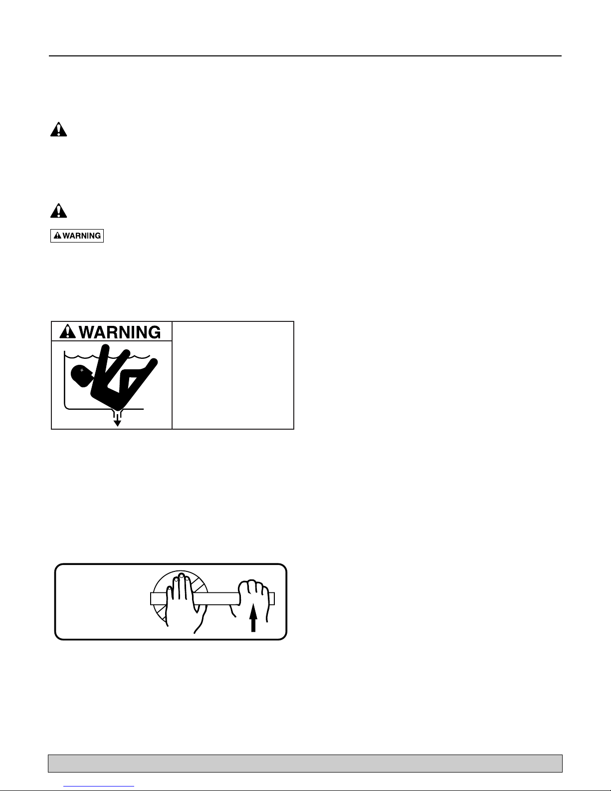
Figure 5 – Use a pry bar or board as shown to remove
tight lid.
Hazardous Suction.
Can trap hair or body,
causing severe injury
or death.
• Do not block suction.
• Keep small children
under close adult
supervision at all times.
TO REMOVE
OVERTIGHT
BOARD
LID

Operation / Pump Service 9
For parts or assistance, call Flotec Customer Service at 1-800-365-6832
Draining Pump
Hazardous voltage. Can shock, burn or
cause death. Disconnect power before working on pump
or motor.
1. Pump down water level below all inlets to the pool.
To avoid dangerous or fatal electrical shock
hazard, turn OFF power to motor before drain-
ing pump.
2. Remove trap cover and use low pressure air to blow
accumulated water from the piping system. Use a pry
bar or board to remove trap covers that have been
overtightened or have taken a set and cannot be
removed by hand. Lugs have been provided on the
trap lid to use a lever or pry bar for loosening (see
Figure 5). Do not use high pressure air to purge system.
3. Cap inlet piping after draining to keep water out of
the pipes.
4. To prevent pump from freezing, remove trap cover
and drain the tank body through the two drain plugs
provided. Clean pump thoroughly; replace trap cover.
NOTICE: Tighten trap cover by hand only (no
wrenches)! If pump is not anchored, use caution to
avoid breaking attached piping!
5. Be sure motor is kept dry and covered.
Startup For Winterized Equipment
1. Remove any temporary weather protection placed
around system for shutdown.
2. Follow filter manufacturer’s instructions for reactivation of the filter.
3. Inspect all electrical wiring for damage or deterioration over the shutdown period. Have a qualified serviceman repair wiring as needed.
4. Inspect and tighten all watertight connections.
5. Open all valves in suction and return piping.
6. Remove any winterizing plugs in piping system.
7. Drain all antifreeze from system.
8. Close all drain valves and replace all drain plugs in
piping system.
9. Prime pump according to instructions on Page 8.
PUMP SERVICE
Pump should only be serviced by qualified personnel.
For best results, use only genuine factory parts.
Be sure to prime pump (Page 8) before starting.
Before removing trap cover:
1. STOP PUMP before proceeding.
2. CLOSE GATE VALVES in suction and discharge pipes.
3. RELEASE ALL PRESSURE from pump and piping
system.
Hazardous voltage. Can shock, burn or
cause death. Disconnect power before working on pump
or motor.
Aside from lubricating trap cover O-Ring, no lubrication
or regular maintenance is needed beyond reasonable
care and periodic cleaning of strainer basket.
If shaft seal is worn or damaged, repair as follows:
Pump Dissasembly/Removing Old Seal
Disconnect power to pump motor.
Be sure gate valves on suction and return piping
are closed before starting work.
Release all pressure by opening all vents before starting
work.
1. Drain pump by removing drain plugs on bottom of
pump body and trap body.
2. Be sure there is no pressure in trap body; remove
cover (unscrew by turning counterclockwise).
3. Remove 6 nuts, lockwashers and flat washers holding
seal plate to pump body. Pull seal plate and motor
away from pump body. (You may have to CAREFULLY use a screwdriver to separate body from seal
plate.)
4. Remove seven screws and washers holding diffuser to
seal plate. Remove diffuser.
5. Remove motor canopy. Being careful not to touch
capacitor terminals, loosen capacitor clamp and
move capacitor to one side.
6. Hold shaft with 7/16" open-end wrench on motor
shaft flats.
7. Unscrew impeller from shaft (turn counterclockwise
when facing it).
Pump Service 10
For parts or assistance, call Flotec Customer Service at 1-800-365-6832
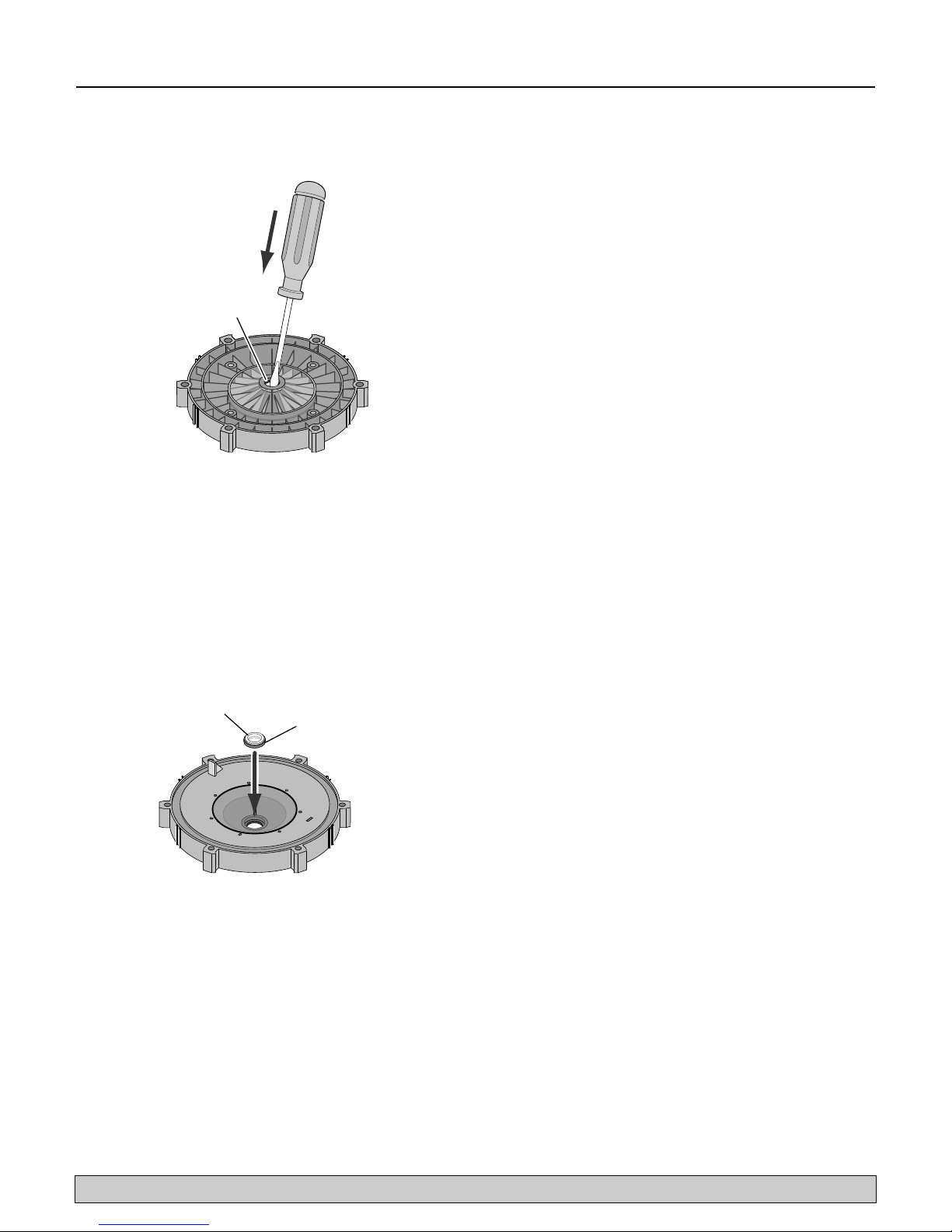
8. Remove four screws holding seal plate to motor.
9. Place seal plate face down on flat surface and tap out
ceramic seat (Figure 6).
10.Remove slinger from motor shaft and inspect for damage or abrasion.
11. Clean seal cavity in seal plate and clean motor shaft.
Pump Reassembly/Installing New Seal
1. Ceramic seat must be clean and free of dirt, grease,
dust, etc. Wet outer edge with small amount of liquid
detergent; press ceramic seat into seal plate cavity
firmly and squarely with finger pressure (Figure 7).
2. If ceramic seat will not locate properly, remove it,
place face up on bench and reclean cavity. Ceramic
seat should now locate.
3. If seat still will not locate properly, place a cardboard
washer over the polished face and use a piece of 3/4"
(19mm) standard pipe for pressing purposes.
NOTICE: Be sure not to scratch or mar polished surface or seal will leak.
4. Replace slinger on end of motor shaft so that impeller
sleeve will push it into position. If slinger shows signs
of wear or damage, replace it.
5. Remount seal plate on motor. Tighten bolts to 60-80
inch-lbs. (69-92 kg/cm) torque.
6. Apply a small amount of liquid detergent to inside
diameter of rotating half of seal.
7. Slide rotating seal member, polished carbon face out,
over impeller sleeve until rubber drive ring hits back
of impeller.
NOTICE: Be sure not to nick or scratch polished seal
face; seal will leak if face is damaged.
8. Screw impeller onto shaft (clockwise); this will automatically locate seal in seal plate.
9. Mount diffuser on seal plate; tighten screws to 10-14
inch-lbs. (11.2-16.1 kg/cm) torque.
10.Assemble motor and seal plate to pump body with
nuts, flat washers and lock washers. Torque nuts to
120-130 in-lbs. (138-150 kg/cm).
11. Prime pump according to instructions on Page 8.
Figure 6
Figure 7
Mechanical seal
ceramic seat
Polished
surface
Rubber
surface

Troubleshooting 11
For parts or assistance, call Flotec Customer Service at 1-800-365-6832
Hazardous voltage. Can shock, burn or
cause death. Disconnect power before working on pump
or motor.
Read and understand safety and operating instructions in this manual before doing any work on
pump!
Only qualified personnel should electrically test
pump motor!
FAILURE TO PUMP; REDUCED CAPACITY OR
DISCHARGE PRESSURE
Suction leaks/lost prime:
1. Pump must be primed; make sure that pump volute
and trap are full of water. See priming instructions,
Page 8.
2. Make sure there are no leaks in suction piping.
3. Make sure suction pipe inlet is well below the water
level to prevent pump from sucking air.
4. If suction trap gasket is defective, replace it.
5. Make sure pump is not trying to lift water more than
10' (3m).
6. Make sure suction pipe is at least 1-1/2" (38mm) in
diameter.
Clogged pipe/trap/impeller, worn impeller:
7. Make sure suction trap is not clogged; if it is, clean
trap and strainer.
8. Make sure impeller is not clogged (follow steps 1
through 7 under “Removing Old Seal”, Page 9; check
impeller for clogging; follow steps 7 through 11 under
“Installing New Seal”, Page 10, for reassembly).
9. Impeller and diffuser may be worn. If so, order
replacement parts from Repair Parts List, Page 12.
Electrical:
10.Pump may be running too slowly; check voltage at
motor terminals and at meter while pump is running.
If low, see wiring instructions or consult power company. Check for loose connections.
11. Pump may be too hot.
A. Check line voltage; if less than 90% or more than
110% of rated voltage consult a licensed electrician.
B. Increase ventilation.
C. Reduce ambient temperature.
D. Tighten any loose connections.
MECHANICAL TROUBLES AND NOISE
1. If suction and discharge piping are not adequately
supported, pump assembly will be strained. See
“Installation”, Page 4.
2. Do not mount pump on a wooden platform! Securely
mount on concrete platform for quietest performance.
 Loading...