

Page 1

Installation / Troubleshooting Manual
TWINSCAN 3”, GAS AND DIESEL TACH (New LCD)
This manual (part # 1000-158-01) applies to the following product part numbers:
1) 3TB013
2) 3TB013U
3) 3TB014
4) 3TB014M
5) 3TB014U
6) 3TB016
7) 3TB016M
8) 3TB016U
9) 3TB016U-WC
10) 3TB018
11) 3TB018U
12) 3TB023
13) 3TB023M
14) 3TB024
15) 3TB026U
16) 3TB028
17) 3TB028U
18) 3TS013
19) 3TS013M
20) 3TS013U
21) 3TS014
22) 3TS014U
23) 3TS016
24) 3TS016U
25) 3TS023
26) 3TS023U
27) 3TS024
28) 3TS024M
29) 3TS024U
30) 3TS026
31) 3TS026U
32) 3TS026U-WC
33) 3TS028
34) 3TS028U
35) 3TW023
36) 3TW023U
37) 3TW024
38) 3TW024M
39) 3TW024U
40) 3TW026
41) 3TW026M
03/21/2005 1000-190-04
FloScan Instrument Company, Inc. Tel: (206) 524-6625 Fax: (206) 523-4961
Page 2

42) 3TW026U
43) 3TW028
44) 3TW028U
03/21/2005 1000-190-04
FloScan Instrument Company, Inc. Tel: (206) 524-6625 Fax: (206) 523-4961
Page 3
OPERATION
TwinScan 3” Tachometer (LCD)
To ensure years of trouble free operation of your new TwinScan instrument,
please read all of these instructions carefully before beginning your installation.
1. Mounting Location
TwinScan instruments allow you to quickly monitor and compare port and starboard engine performance. The front faces of
all TwinScan
instruments contain magnets that may affect your compass. Use care in choosing a mounting location.
2. Start-up Sequence and Normal Operation
The TwinScan
connections, that the pointers are free, and the LCD display is working properly. Du ring this test, the pointers will sweep smoothly
from zero to full scale and then back to zero. The LCD shows a series of numbers as detailed below (example values are used, so
actual numbers may differ). Switches and configurations are shown on the LCD as: “0123456789AbCdEF”
“8.8.8.8” Checks LCD segments and backlighting.
“ 1.2 0” Software version number.
“F 3” The red (left) and black (right) knob settings (on back of instrument).
“- - 3 4” Internal configuration (scale range, units, etc.)
“ ” Blank
“ 4.0” Cycles per revolution as set by the red and black knobs (refer to calibration sheet—Table 1).
“ ” Blank
After the self-test, the instrument goes into its normal operating mode. The needles indicate engine rpm and the LCD displays a
synch indicator or nautical miles per gallon/liters per nautical mile depending on the “synch / MPG” (“synch / L/NM”) select switch.
3. LCD Synchronizer Indicator
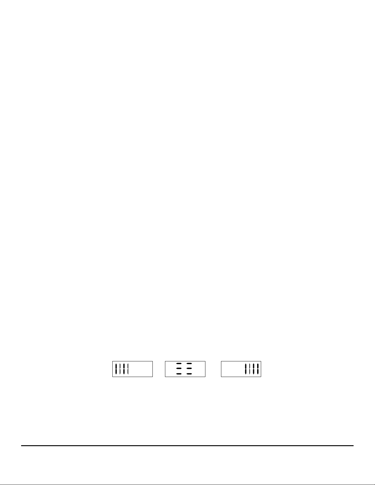
In engine-synch mode, the LCD is programmed to display a bar-graph indicator. A series of vertical bars will appear on the side of
the faster running engine. The number of bars displayed depends on how far the engines are out of synch and the synch resolution
setting on the back of the instrument (see calibration sheet for details). When the engines are synchronized an “IN SYNCH BAR”
appears in the center of the display. When one of the engines is not running, two small rectangles will appear in the corner of the
LCD display. For example, if the starboard engine is at idle and the port engine is not running the two small rectangles will appear in
the bottom left side of the display. Please refer to the diagram below for examples of sync displays.
®
instruments are water-resistant and include a gasket to seal the instrument to the panel. Please note that TwinScan
tachometer performs a quick self-test each time it is powered up. The self-test verifies adequate power, good ground
Port engine running
faster
FIG. 1 SYNCH DISPLAY
5/20/1999 1000-206-00
In Synch
Starboard engine running
faster
FloScan Instrument Company, Inc. Tel: (206) 524-6625 Fax: (206) 523-4961
3016 NE Blakeley Street, Seattle, WA 98105 Email: [email protected] Http://www.floscan.com
Page 4

The number of bars visible in the display indicates how far the engines are out of synch. Referring to the gas engine settings in the
chart below, the display shows one vertical line if the engines are within 200 rpm (coarse) or 100 rpm (fine); it will only indicate
“IN SYNCH” if the engines are within 100 and 50 for the coarse and fine resolution respectively.
Number of bars displayed Coarse (gas) Fine (gas) Coarse (diesel) Fine (diesel)
≡ ≡
|
| |
| | |
| | | |
4. Nautical Miles per Gallon/Liters per Nautical Mile
The TwinScan
instrument) when it is used in conjunction with the TwinScan GPH and a device that outputs a NMEA 0183 data stream (GPS, Loran
C, etc.).
During normal vessel operation, adjusting engine RPM to your maximum MPG (L/NM) reading maximizes your fuel mileage. When
switching fro the synch mode to MPG (L/NM), you will notice the display temporarily indicate MPG—“
L/NM—“
seconds after making a throttle or trim change for the MPG/LPM reading to respond. Vessel trim, load, adjustment of trim tabs, water
currents and weather conditions also affect your fuel consumption. For similar operating conditions, dramatic changes in MPG
(L/NM) readings indicate possible mechanical malfunction, propeller damage or excessive bottom fouling and should be investigated.
Your current MPG (L/NM) reading on the TwinScan Tachometer instrument and GALLONS (LITERS) reading on the TwinScan
GPH (LPH) instrument allow you to quickly and easily estimate your current maximum cruising radius. For safety, allow a margin of
error when calculating your next fuel stop.
5. Illumination
TwinScan instruments use a dual method of illumination to create a high contrast display making it easy to read at night without
affecting your night vision. The pointers are individually lighted so all the port pointers light when the port key switch is energized
and all the starboard pointers light when the starboard key switch is energized. “Light piping” directs the light from an incandescent
across the dial face instead of bouncing it off the dial face and into your eyes.
lamp
6. Caring for your instrument
The front lens of your TwinScan instrument is made of hardened Lexan and is resistant to mild abrasion. Use mild soap and water to
clean. Never wipe with a dry cloth. This can scratch the lens and builds up static electricity attracting dust and dirt. Avoid solvents
such as acetone, benzene, and lacquer thinner as they attack the surface of the lens. Most window and kitchen cleaners contain at
least one of these solvents plus mild abrasives and should be avoided. Applying automobile or furniture wax covers minor scratches
on the lens and helps prevent further scratching.
tachometer displays nautical miles per gallon or liters per nautical mile (depending on the internal configuration of the
m
LPnn” before it starts reading efficiency. The speed and flow data are smoothed for about 30 seconds, so wait for 30-60
100 50 50 20
200 100 100 50
300 250 200 150
400 400 300 300
over 400 Over 400 over 300 over 300
Table 1 Synch resolution
nnPG” or
5/20/1999 1000-206-00
FloScan Instrument Company, Inc. Tel: (206) 524-6625 Fax: (206) 523-4961
3016 NE Blakeley Street, Seattle, WA 98105 Email: [email protected] Http://www.floscan.com
Page 5

INSTALLATION / WIRING
TwinScan 3” Instrument – Tachometer & GPH ******************************
Gas – NMEA 0183 Input (LCD) *COMBINATION ONLY*
******************************
This unit conforms to NMEA 183, Version 1.5 and 2.0 interface standards, and requires a message that includes “VTG”, “RMC” or
“RMA”. Check your owner’s manual to verify your GPS / LORAN-C includes this information. To insure an easy trouble free
installation, read all instructions before starting.
WIRING
1. Refer to the electrical wiring section of the GPS / LORAN-C Owner’s Manual for the proper procedure to connect your GPS /
LORAN-C to NMEA 183 devices. Use shielded wire between instruments and ground the shield ONLY at the GPS / LORAN-C
(sender end), not at the FloScan instrument end (receiver end). The shield is not to be used as a ground path.
2. Connect the WHITE/ORANGE wire to the NMEA (+) (BNC center terminal) terminal coming from your GPS / LORAN-C
instrument.
3. Connect the GREEN/BLACK wire to the NMEA (-) (BNC shield) terminal coming from your GPS / LORAN-C instrument.
4. Connect the BLUE wire to the WHITE/RED wire from the TwinScan GPH meter and to one terminal of a single pole, single
throw switch. Connect the other terminal to the BLACK wire (system ground).
CALIBRATION
1. See your GPS / LORAN-C owner’s manual and set output for NMEA 0183 version 1.5 or 2.0 at 4800 bits/sec. (standard).
Speed is always sent on the NMEA string as speed over ground in knots no matter what units your GPS / LORAN-C displays.
2. Fuel flow rate calibration is automatically done when the totalizer is calibrated. To calibrate, see the Totalizer calibration
instruction page.
FUEL ECONOMY/SYNCH OPERATION
The blue wire must be connected to an operating TwinScan fuel flow meter to show fuel economy, otherwise the instrument shows
the synchronizer regardless of this switch position.
1. With the MPG/SYNCH switch in the ON position (BLUE wire closed, grounded), your instrument displays the engine
synchronizer. In the OFF (open) position, the instrument shows fuel economy in nautical miles per gallon or liters per nautical mile
and is automatically selected by the TwinScan GPH/LPH instrument. You must have valid NMEA 0183 version 1.5 or 2.0 speed
data to display fuel economy; otherwise you receive an error code:
ERROR CODES
Display Reason Cause
“ OFF”
“- - - -”
“- Lo -”
“- hi -”
“Err1”
“Err2”
No signal activity present on NMEA 0183 terminals
for four seconds.
Receiving NMEA 0183 Version 1.5 or 2.0 message,
but speed message is invalid.
(MPG mode) Speed valid but flow rate less than
0.25 GPH.
(LPM mode) Speed valid but less than 0.2 KM.
Some pulsing signal present but no NMEA 0183
message received in last four seconds.
NMEA 0183 message detected, but no “VTG”,
“RMC” or “RMA” sentence found.
GPS / LORAN-C OFF
NMEA OUTPUT not selected
Leads not connected
(+) & (-) leads reversed
GPS satellite reception is poor
GPS / LORAN-C in startup mode
Flow rate too low—engine stopped
Speed too low—boat stopped
Leads connected to wrong source
GPS / LORAN-C set to NMEA 0180 or 0182
(+) & (-) leads reversed.
GPS / LORAN-C incompatible with NMEA 0183,
version 1.5 or newer
5/15/2002 1000-205-00B
FloScan Instrument Company, Inc. Tel: (206) 524-6625 Fax: (206) 523-4961
3016 NE Blakeley Street, Seattle, WA 98105 Email: [email protected] Http://www.floscan.com
Page 6
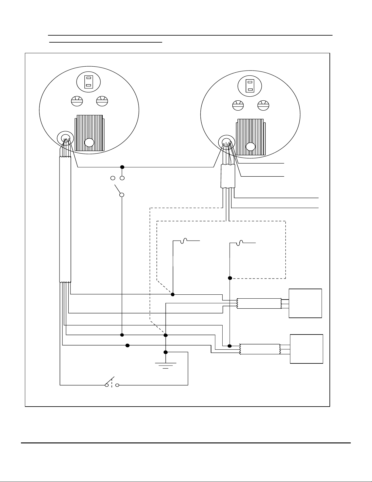
Note: THIS SHEET IS TO BE USED ONLY WHEN INSTALLING A TWINSCAN GPH METER
AND TACHOMETER COMBINED.
Back of GPH Instrument
0 0
Black Switch Red Switch
WHITE/RED BLUE
MPG SYNC
E
L
B
A
C
* Do not use Back-lit, or Illuminated switches
BLACK
RED/WHITE RED
1/2 amp fuse
To Port
key switch
Back of Tachometer
0 0
Black Switch Red Switch
WHITE/ORANGE
E
L
GREEN/BLACK
B
A
C
VIOLET
YELLOW
1/2 amp fuse
To Starboard
key switch
Data (+)
Data (-)
To STARBOARD
tachometer input
To PORT
tachometer input
RED/WHITE
WHITE
RED
BLACK
BROWN
GREEN
Totalizer Reset Switch
* Do not use Back-lit, or Illuminated switches
Battery (-) buss
BLACK
RED
BLACK
WHITE
RED
BLACK
WHITE
R
CABLE
CABLE
B
W
R
B
W
* If installing TwinScan tachometer and
TwinScan GPH Instrument, parallel
power and ground wires as shown.
Otherwise, wire as single instrument
as shown.
PORT
Flow
Sensor
STARBOARD
Flow
Sensor
5/15/2002 1000-205-00B
FloScan Instrument Company, Inc. Tel: (206) 524-6625 Fax: (206) 523-4961
3016 NE Blakeley Street, Seattle, WA 98105 Email: [email protected] Http://www.floscan.com
Page 7
ELECTRICAL
Series 5400(0)/5500(0)/56100/5800(0)/6500(0)/6600(0) AccuTroll & CruiseMaster,
All Multi Function Instruments, & TwinScan
Wire & Switches: Use 18 AWG stranded wire on runs under 50’. For runs over 50’ use 16 AWG. Shielded wire is recommended
for all Diesel systems and suggested for Inboard & I/O gasoline systems. Always, “Ground” the wire shield or shield drain wires in
the engine room by connecting them to the bonding system or engine block. The double wiring harness for twin engine
Pulse/NMEA Diesel installations is included in all, (97/9800(0)) kits. FloScan suggests using J-Boxes, Terminal Blocks, and three
conductor cables between diesel sensors and instrument to make wiring easier.
Install Single Pole Single Throw (SPST) switches for Totalizer Reset, Port–Starboard Select, Engine Hours / Synchronizer, and
GPH / MPG, (switches are not included with kit). To determine which switch types are required for your system, refer to the table
below. All instruments except TwinScan
SYSTEM TOTALIZER RESET
5400(0) SPST or Momentary OFF SPST NA NA NA
5500(0)/56100 SPST or Momentary OFF SPST NA NA NA
5800(0) SPST or Momentary OFF NA NA NA NA
6500(0)/6600(0) SPST or Momentary OFF NA NA NA NA
65/6600(0) Cummins PT SPST or Momentary OFF SPST NA NA NA
7000/8000(0) Gasoline MFI SPST or Momentary ON SPST SPST NA NA
71/8A00(0) MFI - Gasoline
EFI
75/7600(0) Diesel MFI SPST or Momentary ON NA NA NA NA
9000 Gasoline MFI SPST or Momentary ON SPST SPST SPST NA
9A00(0) MFI - Gasoline EFI SPST or Momentary ON NA NA SPST NA
95/96/97/9800(0) SPST or Momentary ON NA NA SPST NA
TwinScan GPH Meter SPST or Momentary ON NA NA NA NA
TwinScan Tachometer NA NA NA NA NA
TwinScan GPH & Tachometer SPST or Momentary ON NA NA NA SPST
NA = Not Applicable
Grounding: Each Black sensor wire must be connected directly to the Black, “Instrument Ground” wire. Use a single wire to
connect the Black wire junction to the battery’s negative terminal, or a ground buss.
Power: FloScan Instruments & sensors operate on 9 to 12 VDC. Voltages exceeding 16 VDC will damage equipment. 24 & 32
VDC systems must be reduced to 12 VDC. Two different types of voltage reducers are available through FloScan.
WIRE CONNECTIONS
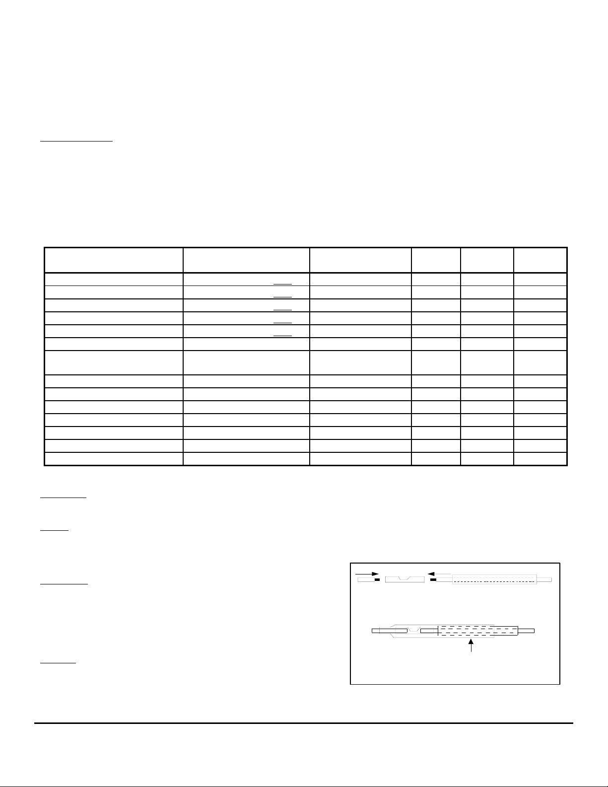
Installation: Connect wires one at a time and install heat shrink tubing
before proceeding to the next wire, (refer to diagram). Connect ground
wires first, (BLACK instrument ground wire to the BLACK sensor
wires). Connect this junction to the battery’s negative terminal or the
ground buss. Connect all other wires leaving the Red power wires for
last to prevent short circuits during installation.
Splicing: Splice or join individual wires per the diagram. Slide heat
shrink tubing over the splices to prevent sho rts. Do not seal splices until
the installation is finished and has been tested.
Tachometers require a totalizer reset switch.
SPST or Momentary ON NA NA NA NA
®
SET UP
PORT/STBD HOURS/
Twin Engine Systems
1. Slide heat shrink tubing
over one wire.
2. Insert wire ends into butt splice.
3. Crimp butt splice.
4. Slide heat shrink tubing
over butt splice.
5. Apply heat.
SYNCH
GPH/
MPG
HEAT
MPG/
SYNCH
5/25/2006 4001-100-00J
FloScan Instrument Company, Inc. Tel: (206) 524-6625 Fax: (206) 523-4961
3016 NE Blakeley Street, Seattle, WA 98105 Email: [email protected] Http://www.floscan.com
Page 8

An adequate number of crimp-on connectors and heat-shrink tubing are included with system. The heat-shrink is a special type that
will bond to wire insulation and make a watertight connection. See diagram for proper tubing application. Crimp-on connectors are
sized for 18 or 20 gauge stranded wire.
Tachometer Wiring Information applies only to MFI & TwinScan Instrument Tachometers
Tachometer signal wires on MFI & TwinScan Tachometers should be shielded.
For proper tachometer operation on gasoline EFI engines, (especially outboards) the engine Ground wire must be physically
connected to the MFI or TwinScan instrument ground wire.
Note: FloScan recommends using dedicated 18 AWG shielded cable for tachometer signal wire connections. Always, “Ground”
wire shields or the shield drain wire in the engine room by connecting to the bonding system or engine block.
MULTI FUNCTION & TWINSCAN INSTRUMENT TACHOMETERS for CARBURETOR & CLOSED LOOP EFI
GASOLINE ENGINES POINTS or STANDARD ELECTRONIC IGNITIONS
Inboard, & I/O Engines: Connect the YELLOW wire from pin # 8 to the distributor coil’s negative terminal. On twin engine
systems the Yellow wire from pin # 8 connects to the port engine, the VIOLET wire from pin # 16 to starboard.
Outboard Engines: Outboard tachometers are connected to either the engine alternator or tachometer signal wire. Connect the
YELLOW wire from pin # 8 to the engine alternator or tachometer signal wire. On twin engine systems the Yellow wire from pin #
8 connects to the port engine, the VIOLET wire from pin # 16 to starboard.
MULTI FUNCTION & TWINSCAN INSTRUMENT TACHOMETERS for
CLOSED LOOP EFI GASOLINE ENGINES with CPU IGNITION SYSTEMS
Inboard, I/O, & Outboard Engines: Connect the YELLOW wire from pin # 8 to the engines’ tachometer signal wire. On twin
engine systems the Yellow wire from pin # 8 connects to the port engine, the VIOLET wire from pin # 16 to starboard.
Outboard Engines: Connect the YELLOW wire from pin # 8 to the engines’ tachometer signal wire. On twin engine systems the
Yellow wire from pin # 8 connects to the port engine, the VIOLET wire from pin # 16 to starboard.
MULTI FUNCTION INSTRUMENT TACHOMETERS for
OPEN RETURN EFI GASOLINE ENGINES with CPU IGNITION SYSTEMS
Inboard & I/O Engines: Connect the YELLOW wire, pin # 8 to the engines’ tachometer signal wire.
MULTI FUNCITON INSTRUMENT TACHOMETERS -
• Keep existing tachometer: Connect the YELLOW and VIOLET wires to the existing tachometer signal wires. If one lead is
grounded at the pickup or alternator, connect the YELLOW wire to the tachometer signal wire. Connect the VIOLET wire to a
ground buss.
• Replace existing tachometer: Connect the YELLOW and VIOLET wires to the existing magnetic pickup or signal generator. If
one lead is grounded at the pickup or alternator, connect the YELLOW wire to the existing signal wire terminal at the tachometer
and connect the VIOLET wire to a ground buss.
• Install as a new tachometer. On engine alternator installations, connect the YELLOW wire to the tachometer output terminal
(usually marked “tach” or “sig”) and connect the VIOLET wire to a ground buss. For mechanically driven A-C signal generators
and magnetic pickups, connect the YELLOW wire to one terminal and the VIOLET wire to the other.
TWINSCAN INSTRUMENT TACHOMETERS –
• Connect the YELLOW wire to one terminal the Port tachometer sender, (AC signal generator, Magnetic pickup, or the engines’
alternators tach or sig terminal). Connect the VIOLET wire to the Starboard sender. The tachometer senders’ second terminal must
be grounded.
FINAL ACTIONS
Check Electrical Installation: Test all connections. Support and secure all dangling wires. Start engine and calibrate system.
5/25/2006 4001-100-00J
DIESEL ENGINES
DIESEL ENGINES
FloScan Instrument Company, Inc. Tel: (206) 524-6625 Fax: (206) 523-4961
3016 NE Blakeley Street, Seattle, WA 98105 Email: [email protected] Http://www.floscan.com
Page 9

ELECTRICAL
TwinScan Gas & Diesel Tachometer
Tachometer Wiring: For proper tachometer operation on Gasoline EFI engines, (especially outboards) the engine Ground wire must
be directly connected to the TwinScan Tachometer ground wire. FloScan recommends using dedicated 18 AWG shielded cab le for
tachometer signal wire connections. Always, “Ground” wire shield or shield drain wire in the engine room by connecting it to the
bonding system, or engine block.
CARBURETOR & CLOSED LOOP EFI GASOLINE ENGINES with POINTS or STANDARD ELECTRONIC IGNITIONS
Inboard, & I/O Engines: Connect the Yellow tachometer signal wire to the negative terminal of the port engines’ distributor coil.
Connect the Violet tachometer signal wire to the negative terminal of the starboard engines’ distributor coil.
Outboard Engines: Outboard motor tachometers are connected to either the engine alternator or tachometer signal output wire.
Connect the Yellow tachometer signal wire the port engines’ alternator or tachometer signal output wire. Connect the Violet
tachometer signal wire to the starboard engines’ alternator or tachometer signal output wire.
CLOSED LOOP EFI GASOLINE ENGINES with CPU IGNITION SYSTEMS
Inboard, I/O, & Outboard Engines: Connect the Yellow tachometer signal wire to the port engines’ tachometer signal output wire.
Connect the Violet tachometer signal wire to the starboard engines’ tachometer signal output wire.
CHRYSLER (Except Magnapower I) - Connect tachometer signal wire(s) to the engine terminal strip marked, “ALT”.
JOHNSON/EVINRUDE/SEADRIVE - Connect tachometer signal wire(s) to the gray wire at key switch harness or Gray/Yellow
alternator wire on engine terminal strip. For 1984 and later model years with standard voltage regulators, connect the tachometer
signal wire(s) to either the Gray voltage regulator wire, or the Yellow/Gray alternator wire on the engine terminal strip.
MERCURY/MARINER - Attach tachometer signal wire(s) to the Yellow/Red, or Yellow wire terminal on engine rectifier.
SUZUKI - Remove three screws from rear of the throttle control box and remove cover plate. Attach tachometer signal wire(s) to the
Yellow wire, and shield ground wire to Black wire. Keep wires away from the moving parts in control box and reinstall back cover.
YAMAHA - Attach tachometer signal wire(s) to the Green wire, and shield ground wire to the Black wire at underside of shift control
box. If the Green wire is not accessible at control box, either Green wire on engine terminal strip can be used.
DIESEL ENGINES
New Installations: TwinScan Diesel Tachometers can use an Engine Alternator, Mechanically Driven AC Signal Generator, or a
Magnetic Pick-Up as the tachometer signal source.
• Engine Alternator: Connect the Yellow tachometer signal wire to the port alternators’ tachometer output terminal (usually
marked “Tach” or “Sig”). Connect the Violet tachometer signal wire to the starboard alternators’ tachometer output terminal.
• Mechanically Driven A-C Signal Generator, Magnetic Pickup: Signal Generators and Magnetic Pick-Ups have two terminals.
One terminal must be connected to battery minus or a ground buss. Connect the Yellow tachometer signal wire to the open
terminal on the port signal generator or magnetic pickup. Connect the VIOLET tachometer signal wire to the open terminal on the
starboard signal generator or magnetic pickup.
Keep or Replace Existing Tachometer: Connect the Yellow tachometer signal wire to the port tachometers signal output wire.
Connect the Violet tachometer signal wire to the starboard tachometers signal output wire. If using an AC Signal Generator or
Magnetic Pick-Up as the tachometer signal source, verify that one terminal is grounded.
FINAL ACTIONS
Check Electrical Installation: Test all connections. Support and secure all dangling wires to prevent accidental breakage. Proceed to
operate system and calibrate.
9/19/2003 7000-039-01
FloScan Instrument Company, Inc. Tel: (206) 524-6625 Fax: (206) 523-4961
3016 NE Blakeley Street, Seattle, WA 98105 Email: [email protected] Http://www.floscan.com
Page 10

9/19/2003 7000-039-01
FloScan Instrument Company, Inc. Tel: (206) 524-6625 Fax: (206) 523-4961
3016 NE Blakeley Street, Seattle, WA 98105 Email: [email protected] Http://www.floscan.com
Page 11
WIRING
Installation Instructions
TwinScan® 3” Instrument – Tachometer Only
Gas and Diesel Engines
To ensure years of trouble free operation of your new TwinScan® Instrument
please read all of these instructions carefully before beginning your installation.
CAUTION: To avoid electrical shorts and possible fire, turn OFF the power to the instrument panel until installation is complete.
WIRING
Use No. 18 AWG multi-strand wire, the included butt splices, and self-sealing heat shrink to make all connections. Alternate
installation: Use insulated ring tongue connectors and a terminal strip. DO NOT solder connections. Vibration can cause wire to
break where solder stops and cause intermittent connections.
Installation: Make a 3 3/8” diameter cutout in the instrument panel for the instrument.
Important: Protect wires from damage caused by sharp edges, moving and hot engine parts. Cable tie and support all wire runs for
safety.
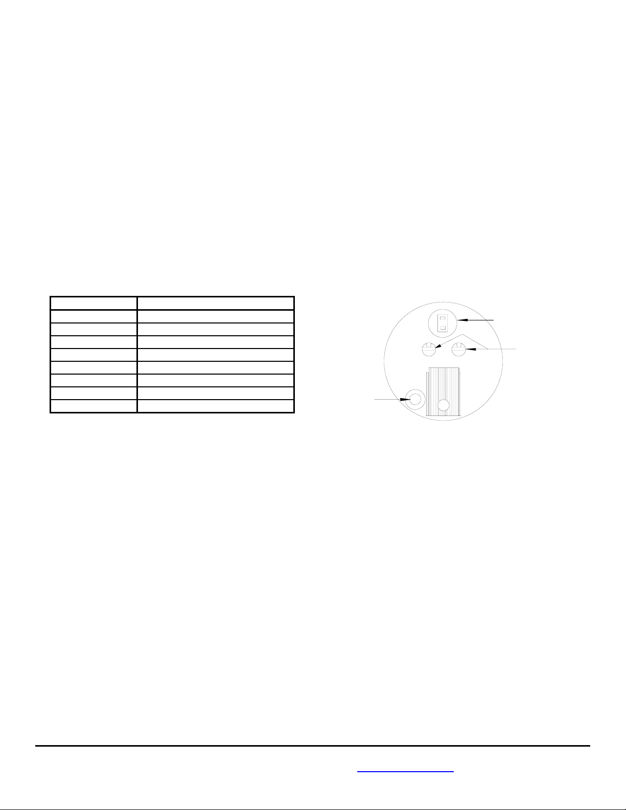
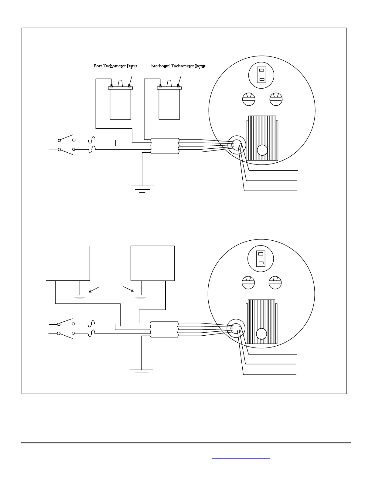
MAIN WIRING
Wire Color Function
RED/WHITE PORT + 12 VDC Power
RED STARBOARD + 12 VDC Power
BLACK Battery Ground
YELLOW PORT tachometer input
VIOLET STARBOARD tachometer input
BLUE Flow Input
WHITE/ORANGE GPS Input, NEMA + (A)
GREEN/BLACK GPS Input, NEMA - (B)
1. Connect the RED/WHITE stripe wire to the “power on” side of the
PORT engine key switch.
2. Connect the RED wire to the “power on” side of the STARBOARD engine key switch.
3. Connect the BLACK wire to the negative (-) side of the battery buss.
4. Connect the YELLOW wire to the PORT engine tachometer pickup.
5. Connect the VIOLET wire to the STARBOARD engine tachometer pickup.
Note: If not installing a TwinScan GPH instrument, leave the following wires disconnected (tape them off).
6. Connect the BLUE wire to the WHITE/RED wire from the TwinScan GPH instrument.
7. Connect the WHITE/ORANGE wire to the GPS (+) terminal (A).
8. Connect the GREEN/BLACK wire to the GPS (-) terminal (B).
NOTE: The industry standard for tachometer pickup wire(s) color coding is as follows:
PORT side = GREY/RED STARBOARD side = GREY/GREEN
This completes the Tachometer wiring. See TACHOMETER CALIBRATION sheet for calibration information.
WIRING SCHEMATIC FOR GAS AND DIESEL TWINSCAN TACHOMETER
10/21/1999 1000-109-00E
FloScan Instrument Company, Inc. Tel: (206) 524-6625 Fax: (206) 523-4961
3016 NE Blakeley Street, Seattle, WA 98105 Email: [email protected] Http://www.floscan.com
Back of Instrument
Dial Lamp
0 0
Black Switch Red Switch
Wires
Calibration Knobs
Page 12
Wiring Schematic For Gas
Twinscan Tachometer
YELLOW
Starboard Keyswitch
+ 12V
RED
+ 12V
1/2 amp fuses
Port Keyswitch
Wiring Schematic For Diesel
Twinscan Tachometer
Tach Sender
YELLOW
Starboard Keyswitch
+ 12V
+ 12V
Port Keyswitch
10-21-99
RED
1/2 amp fuses
+ 12VDC
Distributor
Coil
RED/WHITE
Battery
Post
Negative
RED/WHITE
Distributor
VIOLET
CABLE
K
C
A
L
B
Battery
Post
Negative
STARBOARDPORT
Tach Sender
VIOLET
CABLE
BLACK
Battery
Post
Negative
Coil
+ 12VDC
Back of Tachometer
0 0
Black Switch Red Switch
WHITE/ORANGE
GREEN/BLACK
BLUE
Back of Tachometer
0 0
Black Switch Red Switch
WHITE/ORANGE
GREEN/BLACK
BLUE
(Used with TwinScan
GPH instrument )
Tape End
Tape End
Tape End
(Used with TwinScan
GPH instrument )
Tape End
Tape End
Tape End
10/21/1999 1000-109-00E
FloScan Instrument Company, Inc. Tel: (206) 524-6625 Fax: (206) 523-4961
3016 NE Blakeley Street, Seattle, WA 98105 Email: [email protected] Http://www.floscan.com
Page 13

CALIBRATION
TwinScan 3” Instrument – Tachometer (LCD)
Diesel Engines
The TwinScan 3” Tachometer is unique in that it can be calibrated for both gasoline and
diesel systems. On the back of the TwinScan 3” Tachometer Instrument, the RED
switch is used for fine calibration. The BLACK switch is used for coarse calibration.
You will use a combination of both switches for proper calibration.
Wires
DIESEL SYSTEM CALIBRATION
Diesel systems have three options for tachometer pick-up styles, Mechanical AC Generator, Magnetic Pick-up, and Alternator.
Table 1 will be used to calibrate any style of tachometer pickup you may have. Please read the section pertaining to your specific
tachometer pick-up style for instructions on calibrating the tachometer.
I. MECHANICAL AC GENERATOR
1. Determine the number of pole pairs of your generator. Some examples are:
Century Brass 8 Stewart Warner 8
Hewitt 8 Synchrostart 30
VDO 4 Motorola 8
2. Determine the ratio of the number of revolutions of the crankshaft drive to the number of revolutions of the tachometer. For
most engines, the ratio is 0.5. If you are not sure of your tachometer drive ratio, you can either check with your local engine
dealer or you can adjust the RED and BLACK switches until you get a reading of 500-800 RPM at a normal idle with the
engine at or near normal operating temperature.
3. Calculate the proper switch setting:
Tachometer drive ratio x number of generator pole pairs = number used to determine RED and BLACK switch settings
from Table 1.
Example: Installation - Caterpillar 3208 with an 8 pole pair generator.
Crankshaft revolution to tachometer drive = 0.5 ratio.
Generator = 8 pole pair.
0.5 (ratio) x 8 (pole pair) = 4 (generator produces 4 pulses per revolution).
The switch setting selection would be as follows:
50 RPM synchronized resolution - RED switch = 3 BLACK switch = 1
20 RPM synchronized resolution - RED switch = 3
BLACK switch = 9
II. MAGNETIC PICK-UP
This instrument must be calibrated at the time of installation to your specific engine in the followin g manner:
1. Determine the number of pulses of the magnetic pick-up per crankshaft revolution. If you are not sure what this is, contact
you local engine dealer and they can provide this information.
Pulses = (number of teeth on gear) x (number of revolutions of gear per crank shaft revolution).
The table steps allow setting to be within +/- 1% to 2% of the actual pulse count. As this applies to both engines, the
synchronizing accuracy is not affected.
2. Locate the number of pulses per crankshaft revolution in Table 1. Select the number closest to your actual pulses per
crankshaft revolution.
Example: Pulses per crank shaft revolution = 160. From Table 1:
50 RPM synchronized resolution - RED switch = B BLACK switch = 6
20 RPM synchronized resolution - RED switch = B BLACK switch = E
III. ALTERNATOR
6/16/2006 1000-207-00
FloScan Instrument Company, Inc. Tel: (206) 524-6625 Fax: (206) 523-4961
3016 NE Blakeley Street, Seattle, WA 98105 Email: [email protected] Http://www.floscan.com
Back of Instrument
0 0
Black Switch Red Switch
Dial Lamp
Calibration Knobs
Page 14
The alternator input usually comes off one of the windings of the alternator before it is rectified. This tachometer signal is
inconsistently inaccurate because of a varying amount of belt slippage depending on the load on the alternator, the dimension of the
belt and the belt tension.
Calibration
You can calibrate the tachometer by two methods:
1. Calibrate to the existing tachometer. Simply rotate the RED and BLACK knobs on the back of the instrument until the two
tachometers agree with each other. The accuracy of this method depends on the accuracy of the existing tachometer at the
RPM to which you calibrate. It is best to compare to the existing tachometer at cruising RPM or higher, not at idle.
2. You need the number of poles the alternator has to determine the number of pulses per revolution. Multiply this times the
ratio of the diameter of the crankshaft pulley. Divide this number by the diameter of the alternator pulley.
3. Locate the number of pulses per crankshaft revolution in Table 1. Select the number closest to your actual pulses per
crankshaft revolution.
Example: Motorola alternator has 12 pole pairs (12 pulses per revolution)
Crank shaft pulley = 10” diameter Alternator pulley = 4” diameter
12 x (10 ÷ 4) = number of pulses per revolution 12 x 2.5 = 30 pulses per revolution.
From Table 1 - 50 RPM synchronized resolution - RED switch = 8 BLACK switch = 3
20 RPM synchronized resolution - RED switch = 8 BLACK switch = B
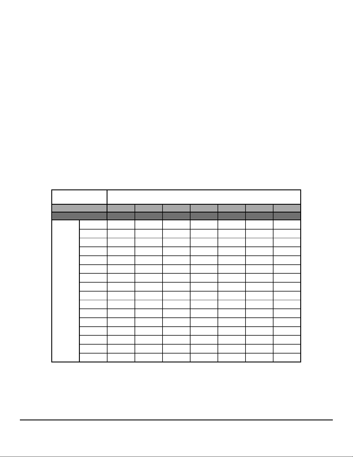
Adjust the RED and BLACK switches for the pulses per revolution according to Table 1:
Table 1 Tachometer Calibration
Synchronized
Resolution
BLACK Switch Setting
20 RPM 9 A B C D E F
0 RPM 1 2 3 4 5 6 7
RED
Switch
Setting
0
1
2
3
4
5
6
7
8
9
A
B
C
D
E
F
1 13.9 23.8 39.5 63.5 111 190
2 14.3 24.5 41 66 114 196
3 14.6 25.3 42.5 69 117 202
4 15 26 44 72 120 208
5 15.4 26.8 45.5 75 123 214
6 15.8 27.5 47 78 126 220
7 16.3 28.3 48.5 81 130 226
8 17 29 50 84 136 232
9 17.8 29.8 51.5 87 142 238
10 18.5 30.5 53 90 148 244
11 19.3 31.3 54.5 93 154 250
12 20 32 56 96 160 256
12.4 20.8 33.5 57.5 99 166 268
12.8 21.5 35 59 102 172 280
13.1 22.3 36.5 60.5 105 178 292
13.5 23 38 62 108 184 304
6/16/2006 1000-207-00
FloScan Instrument Company, Inc. Tel: (206) 524-6625 Fax: (206) 523-4961
3016 NE Blakeley Street, Seattle, WA 98105 Email: [email protected] Http://www.floscan.com
Page 15
y
y
CALIBRATION
TwinScan 3” Instrument – Tachometer (LCD)
Gasoline Engines
TwinScan 3” Tachometers are unique in that they can be used on gasoline and diesel
engines. For gasoline engine calibration refer to the appropriate engine section, Inboard or
Outboard.
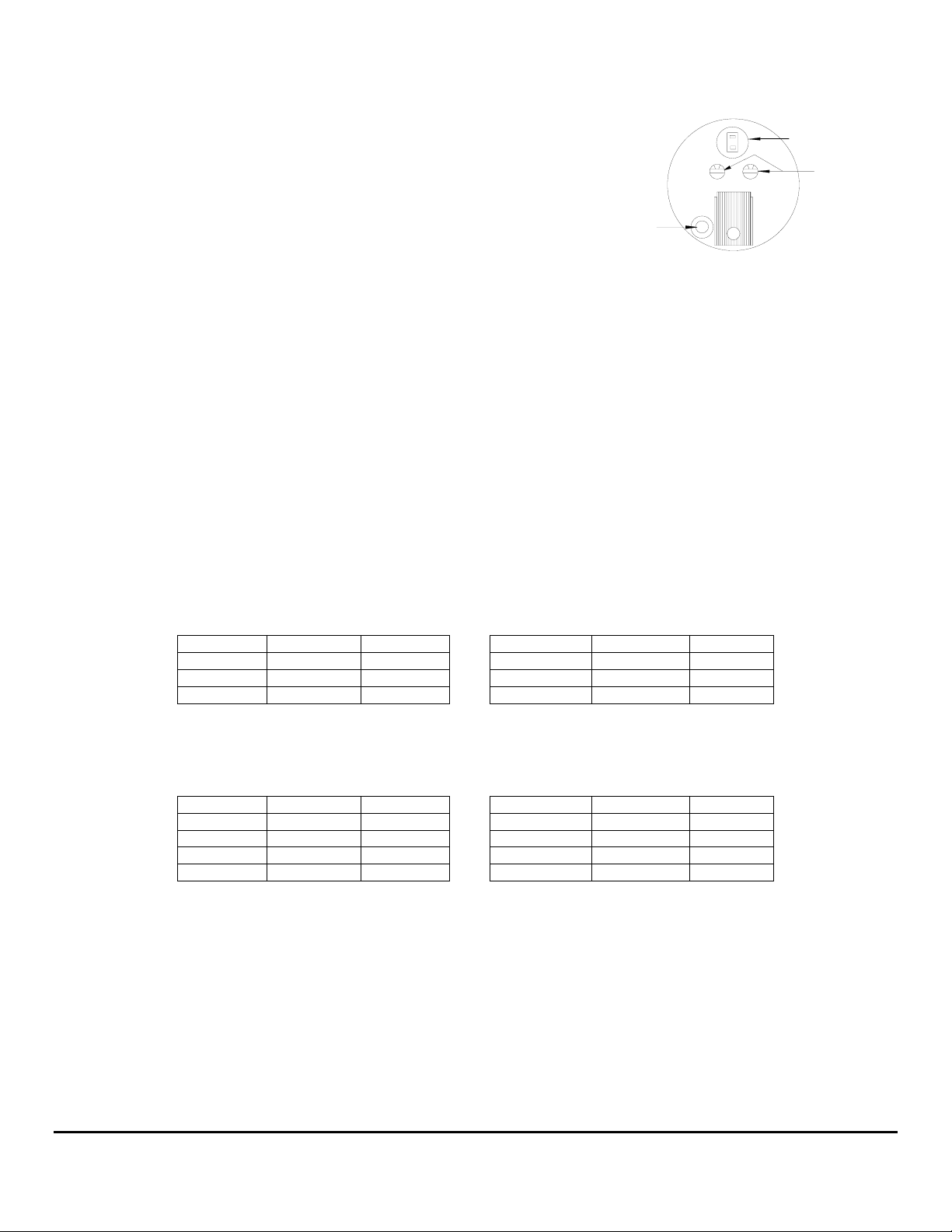
There are two calibration switches on the back of the instrument, Black and Red. Both are
required for calibration. If there’s an existing tachometer, or you know the engines’ idle
RPM, you can calibrate the tachometer without referring to Tables I, II, or III.
Decide on either Coarse or Fine Synch resolution. Coarse resolution shows that the engines are synched when they are running within
100 RPM, fine resolution shows synch within 50 RPM. Begin calibrating by putting the Black switch on 0 or 8, 0 is recommended.
Starting at 0, rotate the Red switch one, “click” at a time until you dial in the correct idle RPM.
• If the correct RPM cannot be dialed in, refer to Table I, II, or III below.
Inboard Engines:
Tachometer calibration for standard point and electronic ignition inboard engines is usually based upon the number of engine
cylinders. EFI engines sometimes use a CPU to generate its tachometer signal. For these engines calibration is not always based on
engine cylinders.
Standard Point & Electronic Ignition Inboard Engines
Coarse Synch Display, (Recommended) Fine Synch Display
linders BLACK RED Cylinders BLACK RED
C
4 0 1 4 8 1
6 0 2 6 8 2
8 0 3 8 8 3
EFI Inboard Engines
Coarse Synch Display, (Recommended) Fine Synch Display
linders BLACK RED Cylinders BLACK RED
C
4, 6, or 8 0 1 4,6, or 8 8 1
4 0 1 4 8 1
6 0 2 6 8 2
8 0 3 8 8 3
Table 1: 4-Cycle Gasoline Inboard Engines
Wires
Back of Instrument
0 0
Black Switch Red Switch
Dial Lamp
Calibration Knobs
7/8/2003 1000-208-00A
FloScan Instrument Company, Inc. Tel: (206) 524-6625 Fax: (206) 523-4961
Page 16
M
Outboard Engines:
Tachometer calibration for standard point and electronic ignition outboard engines is usually based upon the number of alternator pole
pairs. EFI outboards sometimes use a CPU to generate its tachometer signal. Calibration for EFI engines is not always based
alternator pole pairs. Refer to your engine manual or check with a local dealer to determine the number of alternator pole pairs your
engine has.
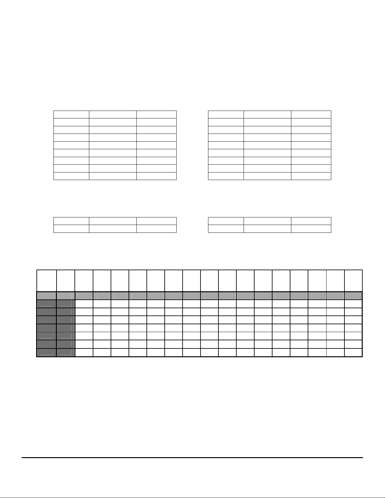
Standard Points, Electronic Ignition, & EFI Outboard Engines
Coarse Synch Display, (Recommended) Fine Synch Display
Pole Pairs Black Switch Red Switch Pole Pairs Black Switch Red Switch
2 0 1 2 8 1
4 0 3 4 8 3
6 0 5 6 8 5
8 0 7 8 8 7
10 0 9 10 8 9
12 0 B 12 8 B
14 0 D 14 8 D
16 0 F 16 8 F
EFI Outboard Engines
Coarse Synch Display, (Recommended) Fine Synch Display
Pole Pairs Black Switch Red Switch Pole Pairs Black Switch Red Switch
CPU 0 1 CPU 8 1
Table II, 2&4-Cycle Gasoline Inboard Engines
Red Switch
0 1 2 3 4 5 6 7 8 9 A B C D E F
1 2 3 4 5 6 7 8 9 10 11 12 12.4 12.8 13.1 13.5
13.9 14.3 14.6 15 15.4 15.8 16.3 17 17.8 18.5 19.3 20 20.8 21.5 22.3 23
23.8 24.5 25.3 26 26.8 27.5 28.3 29 29.8 30.5 31.3 32 33.5 35 36.5 38
39.5 41 42.5 44 45.5 47 48.5 50 51.5 53 54.5 56 57.5 59 60.5 62
63.5 66 69 72 75 78 81 84 87 90 93 96 99 102 105 108
111 114 117 120 123 126 130 136 142 148 154 160 166 172 178 184
190 196 202 208 214 220 226 232 238 244 250 256 268 280 292 304
Black
Switch
00 RPM 50 RP
0 8 1 2 3 4 5 6 7 8 9 10 11 12 13 14 15 16
1 9
2 A
3 B
4 C
5 D
6 E
7 F
Table III: Pulses/Engine Revolution
7/8/2003 1000-208-00A
FloScan Instrument Company, Inc. Tel: (206) 524-6625 Fax: (206) 523-4961
Page 17
TROUBLESHOOTING
TwinScan® 3” Instrument - Tachometer (LCD)
BEFORE CALLING FOR ASSISTANCE, COMPLETE THESE TROUBLESHOOTING CHECKS AND RECORD YOUR
FINDINGS. TECHNICAL SUPPORT REQUIRES THIS INFORMATION BEFORE A RETURN AUTHORIZATION WILL BE
ISSUED. IT TAKES ABOUT 20 MINUTES AND IS VERY IMPORTANT IN ANALYZING SYSTEM PROBLEMS.
Before starting, record instrument model number and switch settings.
MODEL # _____________________ SERIAL # ____________
RED SWITCH POSITION __________ BLACK SWITCH POSITION _________
Perform the Instrument Diagnostic Test First. Record your findings.
I. INSTRUMENT DIAGNOSTIC SELF-TEST
• Secure power to the Red, and Red/White wires, (Turn both key switches OFF).
• Turn power on, (Either to one or both switches). At start-up, the instrument automatically performs a, “Self-test”.
• Verify that the pointer’s back-lighting glows Red, and that the LCD back-light is glowing Green.
• Observe that the pointers smoothly sweep to near full scale, (Slightly above or below) then smoothly drop back to zero.
The LCD display shows the following numbers and letters in sequence. These are examples actual readings may vary. Switch settings
and configurations are shown on the LCD as, “0123456789AbCdEF”.
8.8.8.8 LCD segment and back-lighting check.
1.21 Software version number.
F 3 Red, (Port) and Black (Starboard) switch settings.
- - 34 Internal configuration (scale range, units, etc.)
Blank
≡ ≡ Synch display, (Indicates normal operation).
NOTE: If Tachometer is powered from on switch, a lower case oo will appear in one corner of the LCD.
• Record the software version __________ and switch settings _____ _____. FloScan Technical Support will ask for these.
The self-test verifies adequate power, a good ground, that the pointers move, and the LCD display is working.
FAULT PROBABLE CAUSE SEE SECTION:
Blank LCD Display Wiring Section II
No back-lighting Wiring/bulb failure Section II
High, Low or No Tachometer Reading Wiring Installation sheet
Calibration Calibration sheet
Fluctuating Tachometer Wiring/continuity Sections II, III
In synch w/engine
Wire Harness Continuity Test Section III
II. SUPPLY VOLTAGE and GROUND TEST
• Measure voltage between the Starboard RED power wire, and the BLACK Instrument ground wire.
• Measure voltage between the Port RED/WHITE power wire, and the BLACK Instrument ground wire.
This reading should be approximately 12 VDC, but not lower than 10 VDC.
3/13/2002 1000-223-00
FloScan Instrument Company, Inc. Tel: (206) 524-6625 Fax: (206) 523-4961
3016 NE Blakeley Street, Seattle, WA 98105 Email: [email protected] Http://www.floscan.com
__________VDC
Page 18

• If 12 VDC is not present, measure between the RED, or RED/WHITE power wire and a known good
ground in the instrument panel. If you measure 12 to 14 VDC there may be an instrument ground problem.
• If 12 to 14 VDC is not present check wiring, switches, fuse, and the 12 VDC power source.
III. CONTINUITY TEST
• Continuity testing requires access to the back of the Instrument and an Ohmmeter. It verifies that wires are not
broken, shorted to ground, another wire, or to power. Before starting, secure all power. You will be testing the
VIOLET, and YELLOW wires.
• Disconnect the Yellow wire harness conductor from the Port Tachometer Sender & Instrument wire.
Connect a jumper from the YELLOW wiring harness conductor to a known good ground. At the
Instrument, connect an Ohmmeter lead to its’ YELLOW wiring harness conductor. Connect the other
Ohmmeter Lead to a known, good ground. The Ohmmeter should read approximately 0.1 to 3 Ω. (Ohm Reading)
• Disconnect the VIOLET wire harness conductor from the Port Tachometer Sender & Instrument wire.
Connect a jumper from the VIOLET wiring harness conductor to a known good ground. At the
Instrument, connect an Ohmmeter lead to its’ VIOLET wiring harness conductor. Connect the other
Ohmmeter Lead to a known, good ground. The Ohmmeter should read approximately 0.1 to 3 Ω. (Ohm Reading)
IV. TACHOMETER PROBLEMS
Note: Refer to the engine owners’ manual, wiring diagram, installation, and calibration instructions for parts A, B, & C below.
A. NO READING.
• Check continuity of the YELLOW and VIOLET Tachometer signal wires, (Section III). Verify that the tachometer signal wires
are connected at the correct signal output point.
B. HIGH OR LOW READINGS.
• Verify that Tachometer is calibrated correctly.
C. FLUCTUATING READINGS.
• Listen to your engine(s). If engine speed cycles up and down, (when idling or underway) the tachometer reading will follow. This
does not indicate a problem with the Tachometer, but may indicate engine problems.
• Verify that wiring connections are tight, clean and dry. Check continuity while shaking the wires. Ohm readings should be near
zero and remain steady.
• Verify that the tachometer signal wires are connected at the correct signal output point.
This concludes system testing. If problems with your system persist,
contact FloScan Technical Support with testing results.
__________VDC
____________
____________
3/13/2002 1000-223-00
FloScan Instrument Company, Inc. Tel: (206) 524-6625 Fax: (206) 523-4961
3016 NE Blakeley Street, Seattle, WA 98105 Email: [email protected] Http://www.floscan.com
 Loading...