

Page 1

Installation / Troubleshooting Manual
TWINSCAN 3”, GAS GPH (New LCD)
Inboard & IO to 1000 HP, All Outboards
This manual (part # 1000-158-00) applies to the following product part numbers:
1) 3FB010U
2) 3FB010U3
3) 3FB011M1
4) 3FB011M2
5) 3FB012U
6) 3FB012U1
7) 3FB012U2
8) 3FB013U
9) 3FB013U1
10) 3FB013U2
11) 3FB014M2
12) 3FB015U
13) 3FB015U1
14) 3FB016M1
15) 3FB016U
16) 3FB016U1
17) 3FB016U2
18) 3FB018M
19) 3FB018M1
20) 3FB018M2
21) 3FB022U
22) 3FB022U1
23) 3FB022U2
24) 3FB023U
25) 3FB023U1
26) 3FB028M
27) 3FS012U
28) 3FS012U1
29) 3FS012U2
30) 3FS013U
31) 3FS013U1
32) 3FS013U2
33) 3FS015U1
34) 3FS021M
35) 3FS021M1
36) 3FS022U
37) 3FS022U1
38) 3FS022U2
39) 3FS023U
40) 3FS023U2
41) 3FS023U1
04/21/2008 1000-190-02
FloScan Instrument Company, Inc. Tel: (206) 524-6625 Fax: (206) 523-4961
3016 NE Blakeley Street, Seattle, WA 98105 Email: [email protected] Http://www.floscan.com
Page 2

42) 3FS024M2
43) 3FS025U
44) 3FS025U1
45) 3FS026
46) 3FS026U
47) 3FS026U1
48) 3FS026U2
49) 3FS028M
50) 3FS028M1
51) 3FS028M2
52) 3FW012U1
53) 3FW013U2
54) 3FW016U1
55) 3FW020U
56) 3FW020U3
57) 3FW021M
58) 3FW021M1
59) 3FW021M2
60) 3FW022U
61) 3FW022U1
62) 3FW022U2
63) 3FW023U
64) 3FW023U1
65) 3FW023U2
66) 3FW024M
67) 3FW024M2
68) 3FW025U
69) 3FW025U1
70) 3FW025U3
71) 3FW026U
72) 3FW026U1
73) 3FW026U2
74) 3FW028M1
75) 3FW028M2
76) 3FW028M4
77) 3FS018M2
04/21/2008 1000-190-02
FloScan Instrument Company, Inc. Tel: (206) 524-6625 Fax: (206) 523-4961
3016 NE Blakeley Street, Seattle, WA 98105 Email: [email protected] Http://www.floscan.com
Page 3

! !
INSTALLATION PLANNING
READ ME FIRST - Mechanical & Electrical Installation Planning Saves Time!
FloScan systems are not difficult to install. Installing one requires only basic electrical & mechanical skills. With forethought and
planning, your system will be installed with few problems.
I. Installation Preparation:
Review the mechanical installation instructions, then survey your vessel. Determine where the Sensor(s), Pulsation Damper(s), (if
used) Switches and Instruments are to be mounted. Place them at their approximate locations. Measure fuel line lengths between
system components, (Primary Filter, Sensor(s), Damper(s), Engine, and Fuel Tank). Determine fitting sizes and type of fittings needed
for each plumbing connection, (JIC, SAE , N PT, NPTF, or Hose Barb).
FloScan Gasoline, “Hi-Flo” system components have ½” Female NPT ports.
FloScan Gasoline, “Lo-Flo” system components have ¼” Female NPT ports.
Review the electrical installation instructions. Open and survey your vessels wire ways and run 3-conductor cables from each sensor
to the instrument. Tachometers require 1 or 2 additional conductors. If there’s an existing tachometer, its signal wires can be used.
II. Mechanical Installation:
Install or mount the Sensor(s), Pulsation Damper(s), (If required) Instruments and Switches, (Reset, MPG, Port/Starboard, Synch).
III. Plumbing:
Mount sensor(s) where they’re to be installed. On installations using Fabric Braid A-1 Fuel Hose install the correct HB X MNPT
fitting into each sensor. Always assemble fittings using a fuel proof pipe thread sealant.
knife to cut the fuel hose. Next install the hose onto the barb fittings. Hose should not be twisted, have adequate slack, an ample r adius
at all bends and be supported at reasonable distances, approximately 2-4 feet. When clamping hose onto the barbs, use 2 narrow or 1
wide stainless hose clamp on each hose end.
Wire Braid A-1 Aeroquip Type Fuel Hose or Hydraulic Hose: Mount the sensor(s) or sensor assemblies where they’re to be
installed. Mark the hose where it is to be cut. Remove hose and bring it to a hydr aulic shop. Have them cut the hose and install ho se
ends. Reinstall the hoses and install the correct fitting into each sensor or sensor assembly. Always assemble fittings using a fuel proof
pipe thread sealant.
adequately supported at reasonable distances, approximately 2-4 feet. AP-50 copper sealing washers, (Connie Seals) or Flaretite seals
may be required to seal JIC & SAE fittings.
Never use Teflon Tape. Hoses should not be twisted, have adequate slack, an ample radius at all bends and be
IV. Electrical Installation:
Run cables between Sensor(s) and Instrument(s). Cables must be adequately supported at reasonable distances, approximately 2-4
feet. Wire Terminations—Referring to the wiring diagram. Connect Sensor, Instrument and Switches to their respective wires with
crimp type butt or ring connectors. Always cover connectors and wire ends with heat shrink tubing.
V. System Start-Up:
Prime the fuel system and check for leaks. Start and run your engines. Look for leaks and other installation problems. If system is not
operating properly refer to the Troubleshooting Instructions and correct any deficiencies.
VI. Calibration:
When system is running properly, refer to the calibration instructions and calibrate your system.
Never use Teflon Tap e. Use a hose cutter or
5/25/2004 4001-386-01D
FloScan Instrument Company, Inc. Tel: (206) 524-6625 Fax: (206) 523-4961
3016 NE Blakeley Street, Seattle, WA 98105 Email: [email protected] Http://www.floscan.com
Page 4
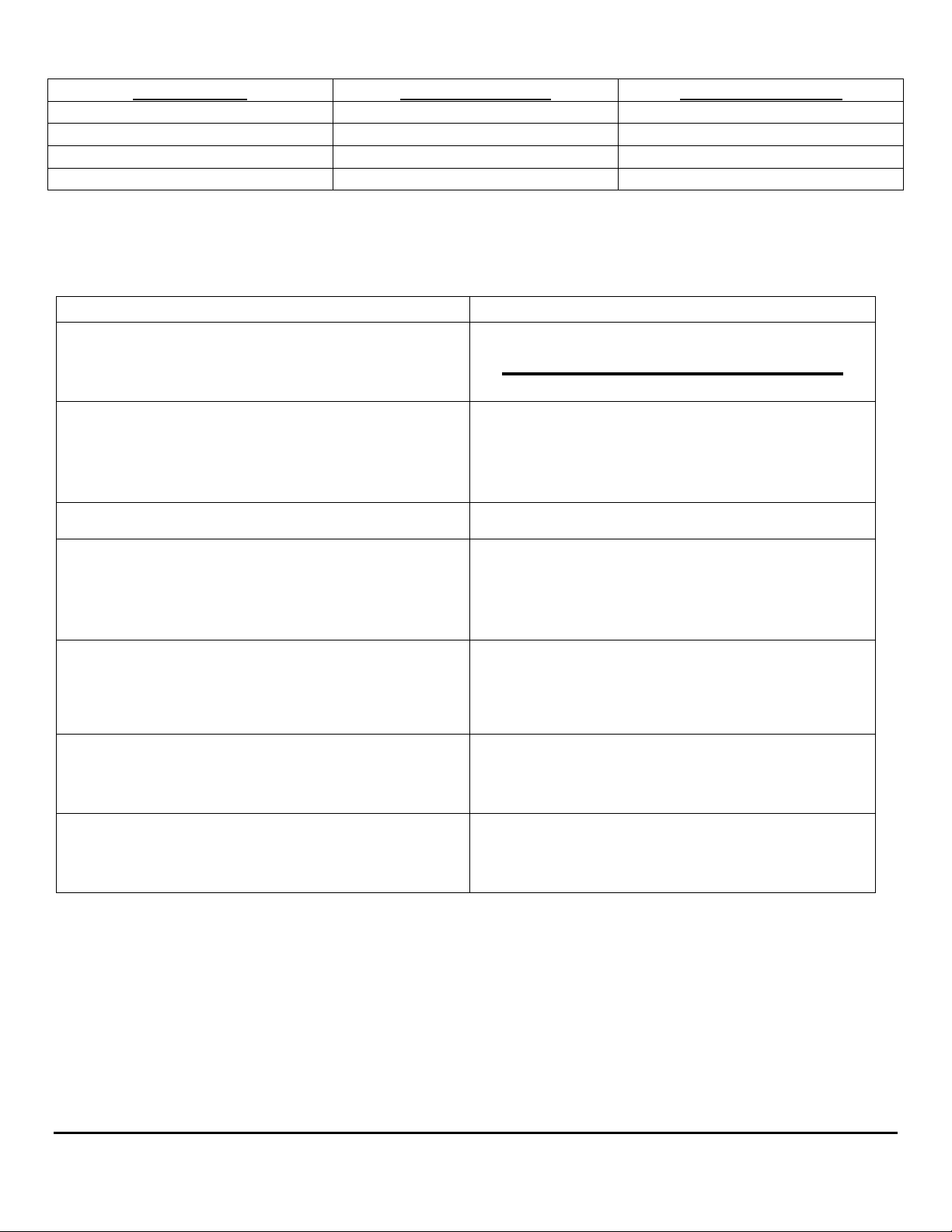
USCG approved fuel hose with either fabric or wire reinforcing braid meet the following standards:
Hose Marking Permeation Rating 2½ Minute Fire Test
USCG Type A-1 100g/m²/24hrs. Required
USCG Type A-2 300g/m²/24hrs. Required
USCG Type B-1 100g/m²/24hrs. Not Required
USCG Type B-2 300g/m²/24hrs. Not Required
Table I
Installation Do’s & Don’ts
Use a Fuel Proof Pipe Thread Sealant when
assembling fittings into fuel system components,
(Locktite PST, Leak-Lock, or equivalent).
Use thin wall, low pressure, full flow type NPT or
NPTF hose barb fittings.
Install Sensor(s) at a low point in the fuel system, as
far from the engine as practical. Fuel must travel,
“Up-hill” slightly after leaving the sensor. Verify
correct orientation and fuel flow direction.
Connect all, “Ground” wires to a Ground Buss, or
directly to the Battery’s Negative Terminal. Connect
or, “Ground” wire shields to the engine block.
On Instruments with a GPS interface, connect
FloScan’s Data (+) to the GPS signal output.
Connect Data (–) to the GPS signal ground.
Always use non-illuminated switches for Totalizer
Reset, Port/Starboard Select, Hours/Synch, and
GPH/MPG.
Double clamp all hose barb fittings.
Do Don’t
Never use Teflon Tape!
Don’t use Push-Lok, or Barb-Tite fittings.
Avoid using JIC or SAE swivel fittings. If used
always install copper conical sealing washers,
(Connie seals) or fitting seals on fittings.
If possible, avoid bolting or mounting sensor(s)
directly onto the engine.
Never connect Instrument or Sensor “Ground”
wires to the hull, engine block, or other
machinery.
Do not connect FloScan’s Data (–) to the GPS
Data (–).
Never use illuminated, or back-lit switches.
Avoid using 90º elbow fittings.
5/25/2004 4001-386-01D
FloScan Instrument Company, Inc. Tel: (206) 524-6625 Fax: (206) 523-4961
3016 NE Blakeley Street, Seattle, WA 98105 Email: [email protected] Http://www.floscan.com
Page 5

OPERATION
TwinScan® 3” GPH Instrument – Gallons Per Hour (LCD)
To ensure years of trouble free operation of your new TwinScan® instrument,
please read all of these instructions carefully before beginning your installation.
1. Mounting Location
The TwinScan
®
GPH instrument allows you to quickly monitor and compare port and starboard engine performance. The front faces
of all TwinScan® instruments are water-resistant and include a gasket to seal the instrument to the panel in which it is installed.
Caution: TwinScan
®
instruments contain magnets that may affect your compass. Use care in choosing your mounting location.
2. Start-up Sequence and Normal Operation
The TwinScan
®
GPH instrument performs a quick self-test each time it is powered up. The self-test verifies adequate power, good
ground connections, that the pointers are free, and the LCD display is working. During this test, the pointers will sweep smoothly
from zero to full scale and then back to zero. The LCD shows a series of numbers as detailed below (example values are used so
actual numbers may be different). Switches and configurations are shown on the LCD as: “0123456789AbCdEF”
“8.8.8.8” Checks LCD segments and backlighting.
“ 1.21” Software version number.
“F 3” The red (left) and black (right) switch settings.
“- - 34” Internal configuration (scale range, units, etc.)
“ ” Blank
“123.4” Current total gallons or total liters (normal operation).
After the self-test, the instrument goes into its normal operating mode. The needles indicate fuel flow in gallons (or liters) per hour
and the LCD shows the total gallons (or liters) consumed since the last reset.
3. Testing the Totalizer
The TwinScan GPH instrument has a non-volatile memory to track the total fuel consumed and therefore can only be reset by holding
the reset switch in the “RESET” position for approximately 15 seconds. You will notice the LCD totalizer blinking during the reset
mode—warning you that it is about to reset. After 10-15 seconds, the LCD will blink “E 0.0”. Release the switch to return to
normal operation.
4. Illumination
TwinScan
®
instruments use a dual method of illumination to create a high contrast display making it easy to read at night without
affecting your night vision. The pointers are individually lighted so all the port pointers light when the port key switch is energized
and all the starboard pointers light when the starboard key switch is energized. “Light piping” directs the light from an incandescent
across the dial face instead of bouncing it off the dial face and into your eyes.
lamp
5. Caring For Your Instrument
The front lens of your TwinScan
®
instrument is made of hardened Lexan and is resistant to mild abrasion. Use mild soap and water to
clean. Never wipe with a dry cloth. This can scratch the lens and builds up static electricity attracting dust and dirt. Avoid solvents
such as acetone, benzene, and lacquer thinner as they attack the surface of the lens. Most window and kitchen cleaners contain at
least one of these solvents plus mild abrasives and should be avoided. Applying automobile or furniture wax covers minor scratches
on the lens and helps prevent further scratching.
6/14/2006 1000-203-00
FloScan Instrument Company, Inc. Tel: (206) 524-6625 Fax: (206) 523-4961
3016 NE Blakeley Street, Seattle, WA 98105 Email: [email protected] Http://www.floscan.com
Page 6
INSTALLATION / WIRING
TwinScan 3” Instrument – Tachometer & GPH ******************************
Gas – NMEA 0183 Input (LCD) *COMBINATION ONLY*
******************************
This unit conforms to NMEA 183, Version 1.5 and 2.0 interface standards, and requires a message that includes “VTG”, “RMC” or
“RMA”. Check your owner’s manual to verify your GPS / LORAN-C includes this information. To insure an easy trouble free
installation, read all instructions before starting.
WIRING
1. Refer to the electrical wiring section of the GPS / LORAN-C Owner’s Manual for the proper procedure to connect your GPS /
LORAN-C to NMEA 183 devices. Use shielded wire between instruments and ground the shield ONLY at the GPS / LORAN-C
(sender end), not at the FloScan instrument end (receiver end). The shield is not to be used as a ground path.
2. Connect the WHITE/ORANGE wire to the NMEA (+) (BNC center terminal) terminal coming from your GPS / LORAN-C
instrument.
3. Connect the GREEN/BLACK wire to the NMEA (-) (BNC shield) terminal coming from your GPS / LORAN-C instrument.
4. Connect the BLUE wire to the WHITE/RED wire from the TwinScan GPH meter and to one terminal of a single pole, single
throw switch. Connect the other terminal to the BLACK wire (system ground).
CALIBRATION
1. See your GPS / LORAN-C owner’s manual and set output for NMEA 0183 version 1.5 or 2.0 at 4800 bits/sec. (standard).
Speed is always sent on the NMEA string as speed over ground in knots no matter what units your GPS / LORAN-C displays.
2. Fuel flow rate calibration is automatically done when the totalizer is calibrated. To calibrate, see the Totalizer calibration
instruction page.
FUEL ECONOMY/SYNCH OPERATION
The blue wire must be connected to an operating TwinScan fuel flow meter to show fuel economy, otherwise the instrument shows
the synchronizer regardless of this switch position.
1. With the MPG/SYNCH switch in the ON position (BLUE wire closed, grounded), your instrument displays the engine
synchronizer. In the OFF (open) position, the instrument shows fuel economy in nautical miles per gallon or liters per nautical mile
and is automatically selected by the TwinScan GPH/LPH instrument. You must have valid NMEA 0183 version 1.5 or 2.0 speed
data to display fuel economy; otherwise you receive an error code:
ERROR CODES
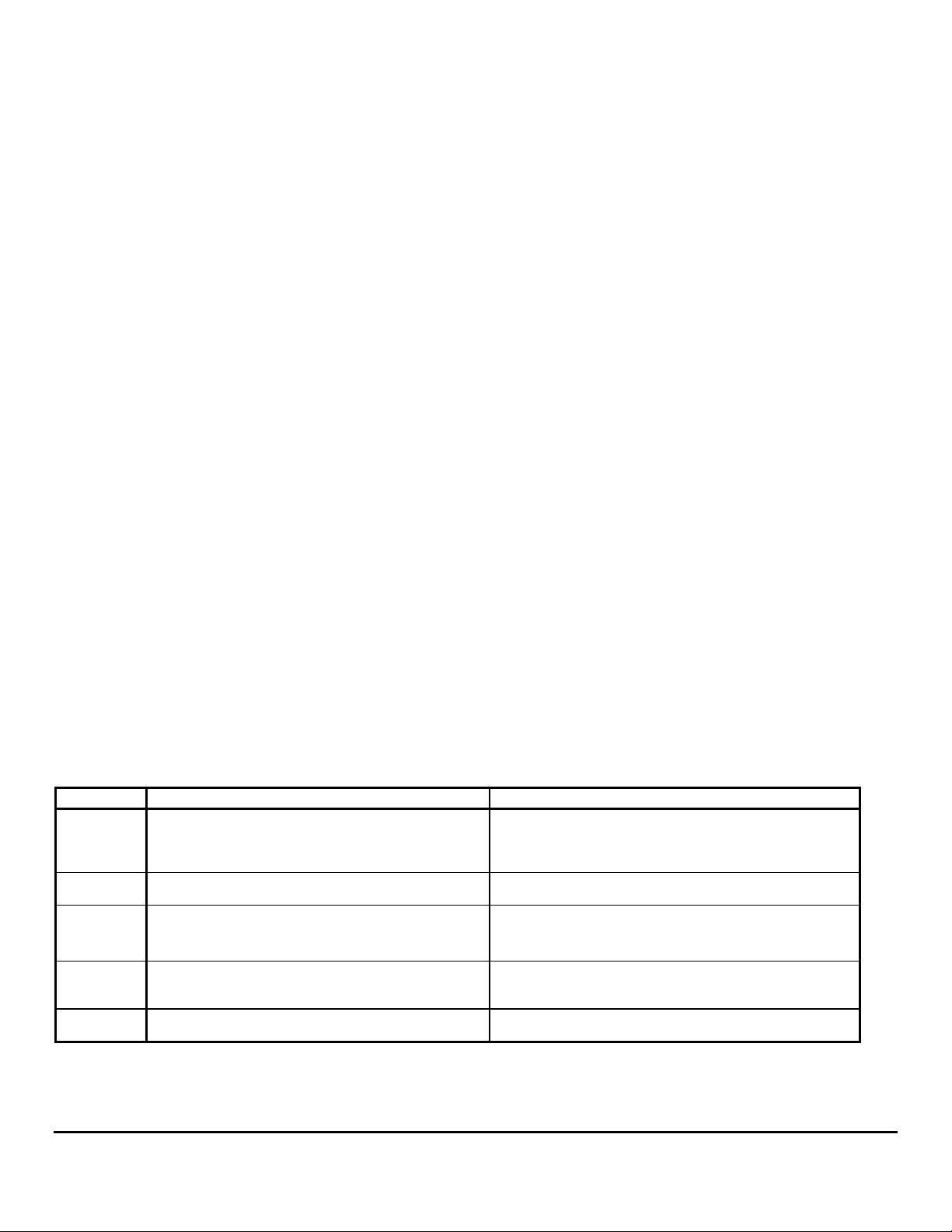
Display Reason Cause
“ OFF”
“- - - -”
“- Lo -”
“- hi -”
“Err1”
“Err2”
No signal activity present on NMEA 0183 terminals
for four seconds.
Receiving NMEA 0183 Version 1.5 or 2.0 message,
but speed message is invalid.
(MPG mode) Speed valid but flow rate less than
0.25 GPH.
(LPM mode) Speed valid but less than 0.2 KM.
Some pulsing signal present but no NMEA 0183
message received in last four seconds.
NMEA 0183 message detected, but no “VTG”,
“RMC” or “RMA” sentence found.
GPS / LORAN-C OFF
NMEA OUTPUT not selected
Leads not connected
(+) & (-) leads reversed
GPS satellite reception is poor
GPS / LORAN-C in startup mode
Flow rate too low—engine stopped
Speed too low—boat stopped
Leads connected to wrong source
GPS / LORAN-C set to NMEA 0180 or 0182
(+) & (-) leads reversed.
GPS / LORAN-C incompatible with NMEA 0183,
version 1.5 or newer
5/15/2002 1000-205-00B
FloScan Instrument Company, Inc. Tel: (206) 524-6625 Fax: (206) 523-4961
3016 NE Blakeley Street, Seattle, WA 98105 Email: [email protected] Http://www.floscan.com
Page 7
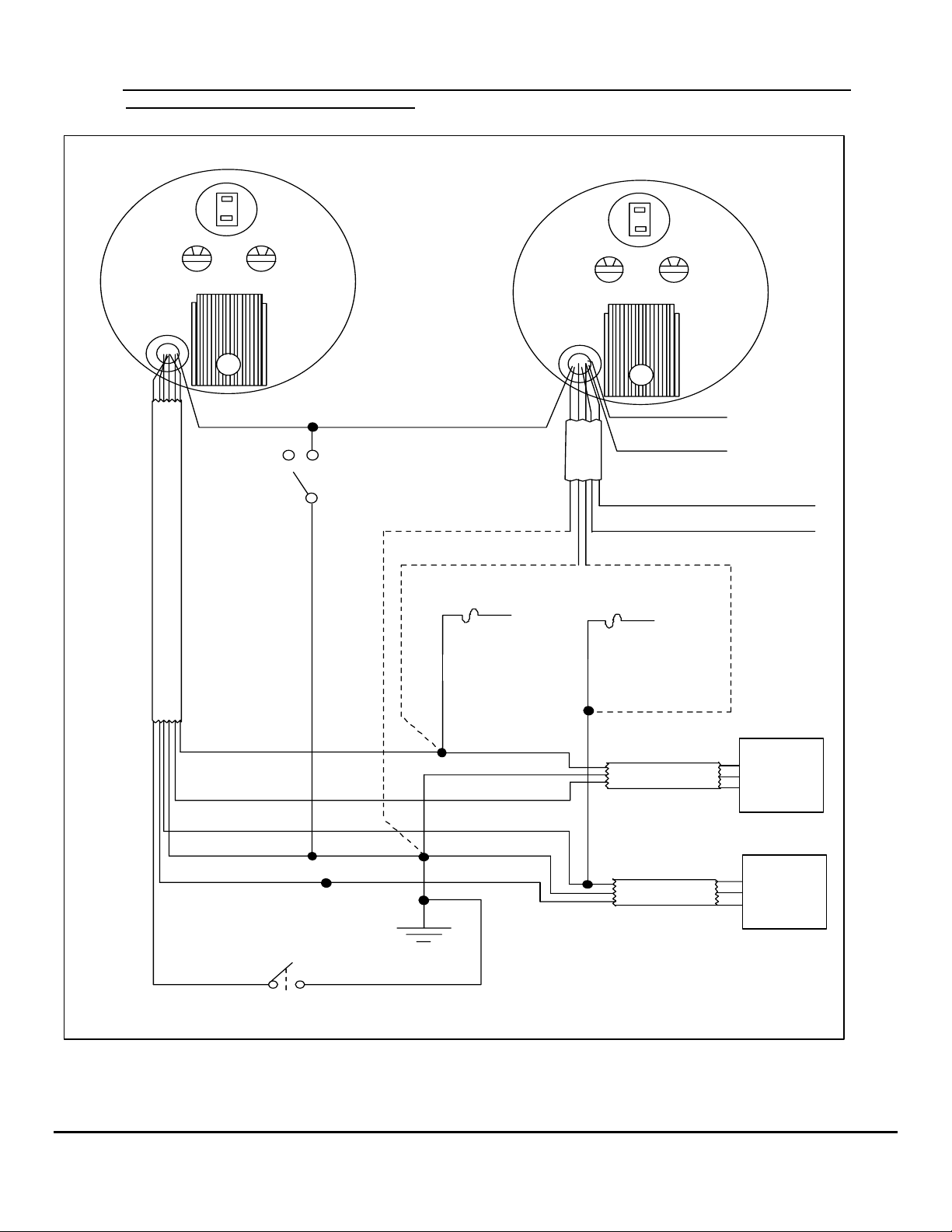
Note: THIS SHEET IS TO BE USED ONLY WHEN INSTALLING A TWINSCAN GPH METER
AND TACHOMETER COMBINED.
Back of GPH Instrument
0 0
Black Switch Red Switch
WHITE/RED BLUE
MPG SYNC
E
L
B
A
C
* Do not use Back-lit, or Illuminated switches
BLACK
RED/WHITE RED
1/2 amp fuse
To Port
key switch
Back of Tachometer
0 0
Black Switch Red Switch
WHITE/ORANGE
E
L
GREEN/BLACK
B
A
C
VIOLET
YELLOW
1/2 amp fuse
To Starboard
key switch
Data (+)
Data (-)
To STARBOARD
tachometer input
To PORT
tachometer input
RED/WHITE
WHITE
RED
BLACK
BROWN
GREEN
Totalizer Reset Switch
* Do not use Back-lit, or Illuminated switches
Battery (-) buss
BLACK
RED
BLACK
WHITE
RED
BLACK
WHITE
R
CABLE
CABLE
B
W
R
B
W
* If installing TwinScan tachometer and
TwinScan GPH Instrument, parallel
power and ground wires as shown.
Otherwise, wire as single instrument
as shown.
PORT
Flow
Sensor
STARBOARD
Flow
Sensor
5/15/2002 1000-205-00B
FloScan Instrument Company, Inc. Tel: (206) 524-6625 Fax: (206) 523-4961
3016 NE Blakeley Street, Seattle, WA 98105 Email: [email protected] Http://www.floscan.com
Page 8
ELECTRICAL
Series 5400(0)/5500(0)/56100/5800(0)/6500(0)/6600(0) AccuTroll & CruiseMaster,
All Multi Function Instruments, & TwinScan
Wire & Switches: Use 18 AWG stranded wire on runs under 50’. For runs over 50’ use 16 AWG. Shielded wire is recommended
for all Diesel systems and suggested for Inboard & I/O gasoline systems. Always, “Ground” the wire shield or shield drain wires in
the engine room by connecting them to the bonding system or engine block. The double wiring harness for twin engine
Pulse/NMEA Diesel installations is included in all, (97/9800(0)) kits. FloScan suggests using J-Boxes, Terminal Blocks, and three
conductor cables between diesel sensors and instrument to make wiring easier.
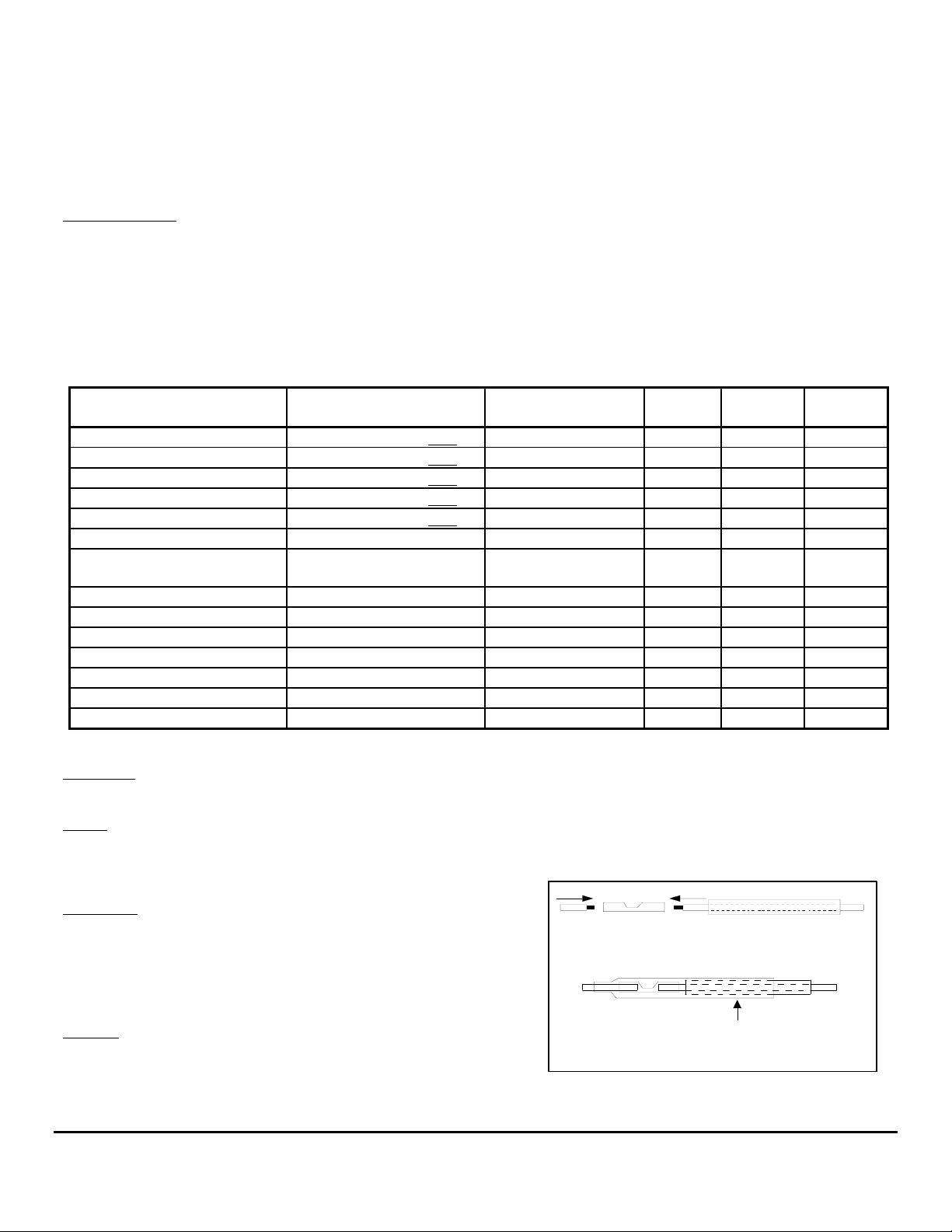
Install Single Pole Single Throw (SPST) switches for Totalizer Reset, Port–Starboard Select, Engine Hours / Synchronizer, and
GPH / MPG, (switches are not included with kit). To determine which switch types are required for your system, refer to the table
below. All instruments except TwinScan
SYSTEM TOTALIZER RESET
5400(0) SPST or Momentary OFF SPST NA NA NA
5500(0)/56100 SPST or Momentary OFF SPST NA NA NA
5800(0) SPST or Momentary OFF NA NA NA NA
6500(0)/6600(0) SPST or Momentary OFF NA NA NA NA
65/6600(0) Cummins PT SPST or Momentary OFF SPST NA NA NA
7000/8000(0) Gasoline MFI SPST or Momentary ON SPST SPST NA NA
71/8A00(0) MFI - Gasoline
EFI
75/7600(0) Diesel MFI SPST or Momentary ON NA NA NA NA
9000 Gasoline MFI SPST or Momentary ON SPST SPST SPST NA
9A00(0) MFI - Gasoline EFI SPST or Momentary ON NA NA SPST NA
95/96/97/9800(0) SPST or Momentary ON NA NA SPST NA
TwinScan GPH Meter SPST or Momentary ON NA NA NA NA
TwinScan Tachometer NA NA NA NA NA
TwinScan GPH & Tachometer SPST or Momentary ON NA NA NA SPST
NA = Not Applicable
Grounding: Each Black sensor wire must be connected directly to the Black, “Instrument Ground” wire. Use a single wire to
connect the Black wire junction to the battery’s negative terminal, or a ground buss.
Power: FloScan Instruments & sensors operate on 9 to 12 VDC. Voltages exceeding 16 VDC will damage equipment. 24 & 32
VDC systems must be reduced to 12 VDC. Two different types of voltage reducers are available through FloScan.
WIRE CONNECTIONS
Installation: Connect wires one at a time and install heat shrink tubing
before proceeding to the next wire, (refer to diagram). Connect ground
wires first, (BLACK instrument ground wire to the BLACK sensor
wires). Connect this junction to the battery’s negative terminal or the
ground buss. Connect all other wires leaving the Red power wires for
last to prevent short circuits during installation.
Splicing: Splice or join individual wires per the diagram. Slide heat
shrink tubing over the splices to prevent sho rts. Do not seal splices until
the installation is finished and has been tested.
Tachometers require a totalizer reset switch.
SPST or Momentary ON NA NA NA NA
®
SET UP
PORT/STBD HOURS/
Twin Engine Systems
1. Slide heat shrink tubing
over one wire.
2. Insert wire ends into butt splice.
3. Crimp butt splice.
4. Slide heat shrink tubing
over butt splice.
5. Apply heat.
SYNCH
GPH/
MPG
HEAT
MPG/
SYNCH
5/25/2006 4001-100-00J
FloScan Instrument Company, Inc. Tel: (206) 524-6625 Fax: (206) 523-4961
3016 NE Blakeley Street, Seattle, WA 98105 Email: [email protected] Http://www.floscan.com
Page 9

An adequate number of crimp-on connectors and heat-shrink tubing are included with system. The heat-shrink is a special type that
will bond to wire insulation and make a watertight connection. See diagram for proper tubing application. Crimp-on connectors are
sized for 18 or 20 gauge stranded wire.
Tachometer Wiring Information applies only to MFI & TwinScan Instrument Tachometers
Tachometer signal wires on MFI & TwinScan Tachometers should be shielded.
For proper tachometer operation on gasoline EFI engines, (especially outboards) the engine Ground wire must be physically
connected to the MFI or TwinScan instrument ground wire.
Note: FloScan recommends using dedicated 18 AWG shielded cable for tachometer signal wire connections. Always, “Ground”
wire shields or the shield drain wire in the engine room by connecting to the bonding system or engine block.
MULTI FUNCTION & TWINSCAN INSTRUMENT TACHOMETERS for CARBURETOR & CLOSED LOOP EFI
GASOLINE ENGINES POINTS or STANDARD ELECTRONIC IGNITIONS
Inboard, & I/O Engines: Connect the YELLOW wire from pin # 8 to the distributor coil’s negative terminal. On twin engine
systems the Yellow wire from pin # 8 connects to the port engine, the VIOLET wire from pin # 16 to starboard.
Outboard Engines: Outboard tachometers are connected to either the engine alternator or tachometer signal wire. Connect the
YELLOW wire from pin # 8 to the engine alternator or tachometer signal wire. On twin engine systems the Yellow wire from pin #
8 connects to the port engine, the VIOLET wire from pin # 16 to starboard.
MULTI FUNCTION & TWINSCAN INSTRUMENT TACHOMETERS for
CLOSED LOOP EFI GASOLINE ENGINES with CPU IGNITION SYSTEMS
Inboard, I/O, & Outboard Engines: Connect the YELLOW wire from pin # 8 to the engines’ tachometer signal wire. On twin
engine systems the Yellow wire from pin # 8 connects to the port engine, the VIOLET wire from pin # 16 to starboard.
Outboard Engines: Connect the YELLOW wire from pin # 8 to the engines’ tachometer signal wire. On twin engine systems the
Yellow wire from pin # 8 connects to the port engine, the VIOLET wire from pin # 16 to starboard.
MULTI FUNCTION INSTRUMENT TACHOMETERS for
OPEN RETURN EFI GASOLINE ENGINES with CPU IGNITION SYSTEMS
Inboard & I/O Engines: Connect the YELLOW wire, pin # 8 to the engines’ tachometer signal wire.
MULTI FUNCITON INSTRUMENT TACHOMETERS -
• Keep existing tachometer: Connect the YELLOW and VIOLET wires to the existing tachometer signal wires. If one lead is
grounded at the pickup or alternator, connect the YELLOW wire to the tachometer signal wire. Connect the VIOLET wire to a
ground buss.
• Replace existing tachometer: Connect the YELLOW and VIOLET wires to the existing magnetic pickup or signal generator. If
one lead is grounded at the pickup or alternator, connect the YELLOW wire to the existing signal wire terminal at the tachometer
and connect the VIOLET wire to a ground buss.
• Install as a new tachometer. On engine alternator installations, connect the YELLOW wire to the tachometer output terminal
(usually marked “tach” or “sig”) and connect the VIOLET wire to a ground buss. For mechanically driven A-C signal generators
and magnetic pickups, connect the YELLOW wire to one terminal and the VIOLET wire to the other.
TWINSCAN INSTRUMENT TACHOMETERS –
• Connect the YELLOW wire to one terminal the Port tachometer sender, (AC signal generator, Magnetic pickup, or the engines’
alternators tach or sig terminal). Connect the VIOLET wire to the Starboard sender. The tachometer senders’ second terminal must
be grounded.
FINAL ACTIONS
Check Electrical Installation: Test all connections. Support and secure all dangling wires. Start engine and calibrate system.
5/25/2006 4001-100-00J
DIESEL ENGINES
DIESEL ENGINES
FloScan Instrument Company, Inc. Tel: (206) 524-6625 Fax: (206) 523-4961
3016 NE Blakeley Street, Seattle, WA 98105 Email: [email protected] Http://www.floscan.com
Page 10
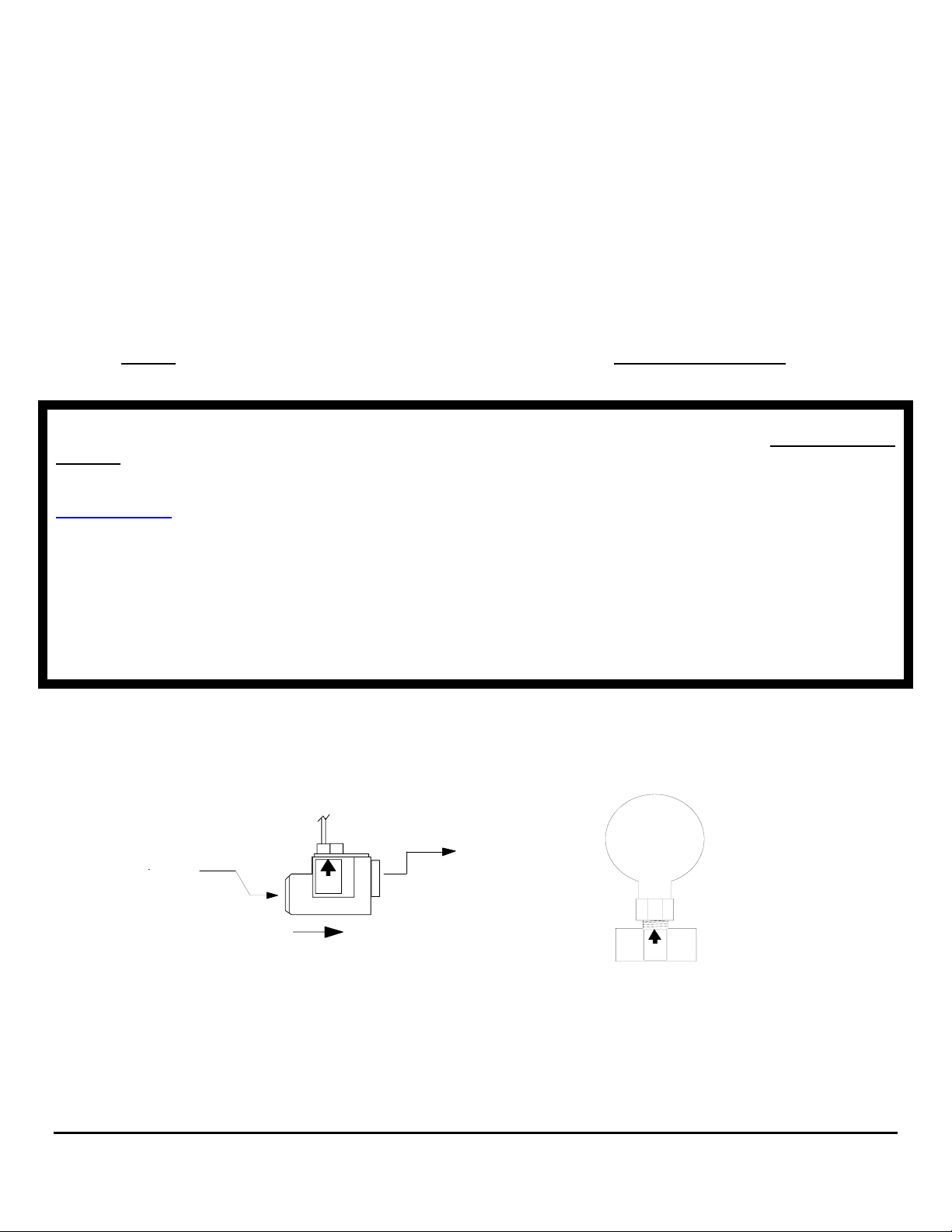
Mechanical Installation
Series 5400(0)/ 5500(0)/ 56100/ 7000(0)/8000(0)/ 9000(0), Single Sensor EFI 8A00(0)/9A00(0) and TwinScan
GPH Instruments for Gasoline Inboard/ I/O/ and Outboard Engines
FLOW SENSOR INSTALLATION
Flow Sensors must be placed in a horizontal section of fuel line at a low point in the fuel system. Fuel should travel, “Up-hill” when
exiting the sensor. Its outlet should be at least 1 or 2 inches lower than the fuel pump inlet, priming bulb or pulsation damper, (if
used). Pulsation Dampers and Priming Bulbs must also be mounted horizontally. Installing sensor(s) 12” upstream of the fuel pump,
priming bulb or pulsation damper improves system accuracy. Install sensors in a protected location, away from water spray.
Model 20A, 20B, 231, & 233C gasoline sensors must be installed downstream of a fuel filter or water separator. On vessels not
equipped with off engine filters, we suggest installing a Flow Ezy model ILA-02 filter with 238 micron screen directly to the 20A,
20B or 231 Low-Flow Sensors’ inlet. Use model 4ILA-04 with 595 micron screens with High Flow 233C Sensors’.
Flow Ezy can be reached at (800) 237-1165.
Caution: NEVER
install sensor(s) downstream of an engine mounted fuel filter. NEVER use Teflon Tape when installing
sensors. Teflon Tape can jam a sensor’s rotor. Instead, always use a fuel proof pipe thread sealant.
For proper system operation, Carburetor Inboard & I/O Engines having diaphragm fuel pumps require Gasoline Pulsation
Dampers. FloScan Systems are not shipped with Pulsation Dampers’ as carburetor Inboard and I/O engines are no longer in
production. If you have a Carburetor Inboard or I/O engine, Pulsation Dampers can be purchased factory direct. Standard
Flow Dampers’ are $30.00 each. The standard Flow Damper can be ordered under Part Number 150-004-00 online at
www.floscan.com in the Accessories section.
E-mail: [email protected], or [email protected].
®
The following engine types DO NOT require Pulsation Dampers:
• Outboard Gasoline Engines Including Ficht, Optimax, 2 & 4-Cycle.
• Most Closed Loop EFI Gasoline Inboard, and I/O Engines.
• Sensors are marked with orientation and fuel flow arrows. They must be installed with these arrows pointing in the right direction.
Standard-Flow Pulsation Damper
20A/ 20B/ 231 SENSOR
Outlet
Inlet
ARROW UP
Fuel Flow Direction
2/15/2007 7000-036-00M
FloScan Instrument Company, Inc. Tel: (206) 524-6625 Fax: (206) 523-4961
3016 NE Blakeley Street, Seattle, WA 98105 Email: [email protected] Http://www.floscan.com
ARROW UP
Page 11
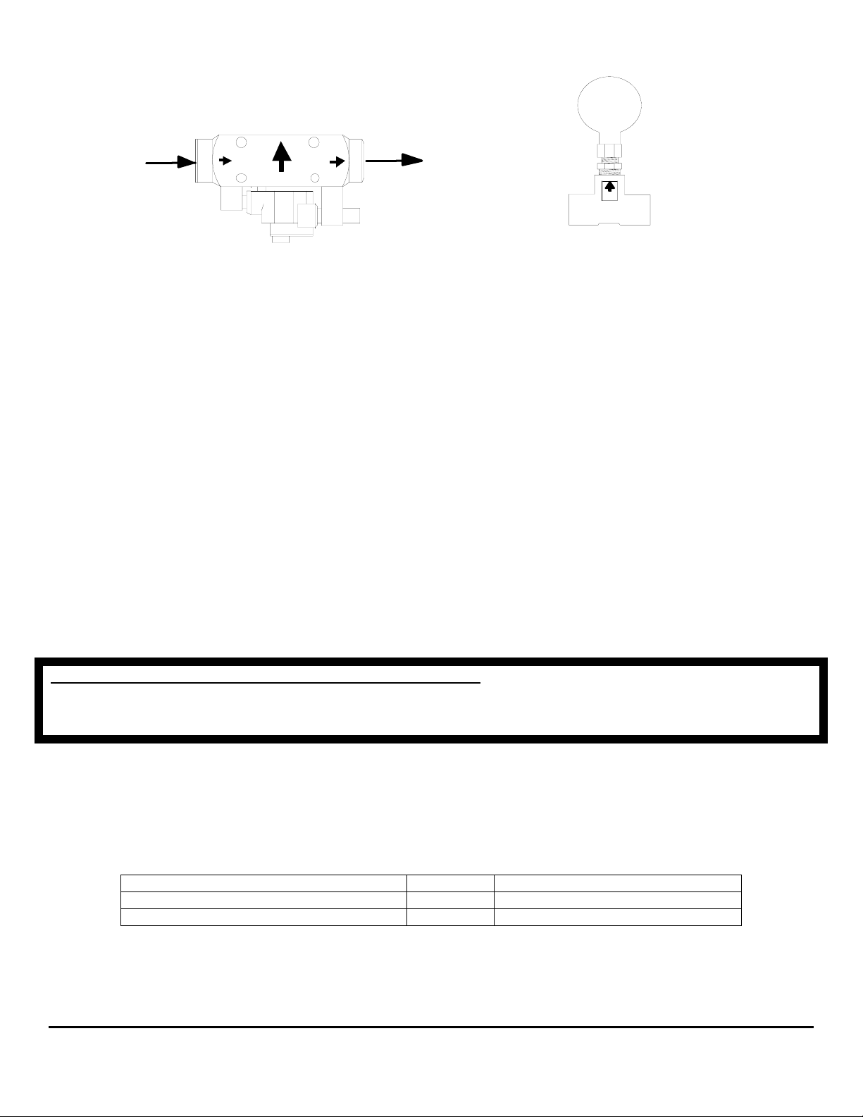
High-Flow Pulsation Damper
233C SENSOR
Inlet
Outlet
ARROW UP
• Install sensor(s) with orientation arrows pointing UP Ï. Fuel must enter through the port marked IN or with an inward pointing
Î fuel flow arrow, and exit through the port marked OUT or with an outward pointing Î arrow.
• The sensor must be installed horizontally at a low point in the fuel system. When fuel exits the sensor it must travel up-hill
slightly. One or two inches of vertical rise is adequate, more is ok.
• The sensor must be installed downstream of, and protected by a screen, filter, or water separator. Sensors are tolerant of fine
debris. A coarse screen, (up to 800 microns) or water separator is all that is required.
• It is recommended that the sensor be installed between the fuel filter and fuel pump inlet. There should be at least twelve inches
of fuel hose, (more is ok) between the sensor and fuel pump inlet.
• If required, the pulsation damper must be installed horizontally, with its orientation arrow pointing up, (refer to fuel flow
schematics below).
• Minimize the number of 90º elbows and pipe fittings. Excessive use may create a high vacuum, fuel restricting pressure drop
across the fuel system. Whenever possible, use a large radius hose bend instead of elbows. Refer to the engine owner’s manual for
maximum fuel pump vacuum. A vacuum gauge can be used to confirm that the system is within limits.
• If swivel fittings are used, (JIC or SAE) their mating surfaces should be sealed with AP 50 Copper Conical Sealing Washers or
Flaretite Fitting Seals. Seals and sealing washers can be purchased through Fittings Inc. in Seattle, WA (206) 767-4670, 1-800552-0632, or a local hydraulic supply house.
CAUTION, DO NOT OVER TIGHTEN FLOW SENSOR FITTINGS.
Over-tightening may crack the sensor’s body. Cracks
cause leaks and fuel leaks sometimes cause catastrophic explosions and fire. Assemble fittings with a Lubricating, Fuel Proof,
Non or Semi Hardening pipe thread sealant, designed for aluminum and stainless steel threads, (Loctite 567 or equivalent).
DO NOT USE TEFLON TAPE.
INSTRUMENT INSTALLATION
• Before cutting holes in your Instrument Panel, verify that the instrument will be installed approximately 12” away from the
compass, and in a shaded location out of direct sunlight. Mounting it within 12” of a compass may interfere with compass
operation. Direct sunlight may cause the LCD display to temporarily turn black due to heat.
Instrument Series Cutout Size Instrument Depth
5400(0), 5500(0) 3 1/16” 3” – Console Panel Thickness
7000(0), 8000(0), 9000(0), TwinScan® 3 3/8” 2 ½” – Console Panel Thickness
Table 1
2/15/2007 7000-036-00M
FloScan Instrument Company, Inc. Tel: (206) 524-6625 Fax: (206) 523-4961
3016 NE Blakeley Street, Seattle, WA 98105 Email: [email protected] Http://www.floscan.com
Page 12
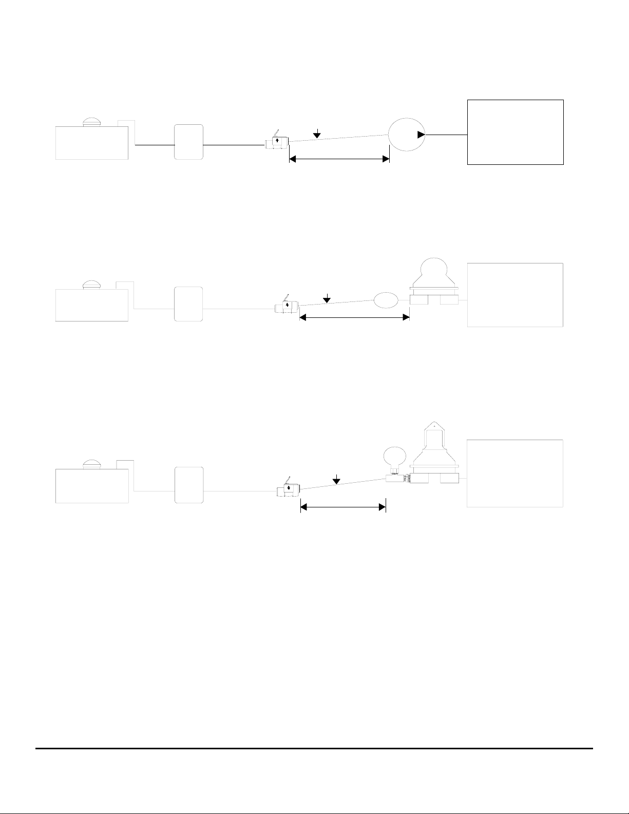
FUEL TANK
Standard-Flow Gasoline System Schematics
Vane, Gear, Gear-Rotor
(EFI & Carburetor Engines)
1" to 2" Minimum
Vertical Rise
ARROW UP
FUEL
FILTER
20A/ 20B/ 231
Flow Sensor
12" Minimum Distance:
A-1 Fabric Braid
Flexible Fuel Line Preferred
Electric
Fuel Pump
ENGINE
Outboard Motor
Diaphragm
Fuel Pump
Priming
Bulb
ENGINE
FUEL TANK
FUEL
FILTER
20A/ 20B/ 231
Flow Sensor
1" to 2" Minimum
Vertical Rise
ARROW UP
12" Minimum Distance:
A-1 Fabric Braid
Flexible Fuel Line Preferred
Engine Driven
Diaphragm Fuel Pump
(Carbureted Inboards and I/O's)
Pulsation
Damper
1" to 2" Minimum
FUEL TANK
FUEL
FILTER
20A/ 20B/ 231
Flow Sensor
Vertical Rise
ARROW UP
ENGINE
12" Minimum Distance:
A-1 Fabric Braid
Flexible Fuel Line Preferred
2/15/2007 7000-036-00M
FloScan Instrument Company, Inc. Tel: (206) 524-6625 Fax: (206) 523-4961
3016 NE Blakeley Street, Seattle, WA 98105 Email: [email protected] Http://www.floscan.com
Page 13
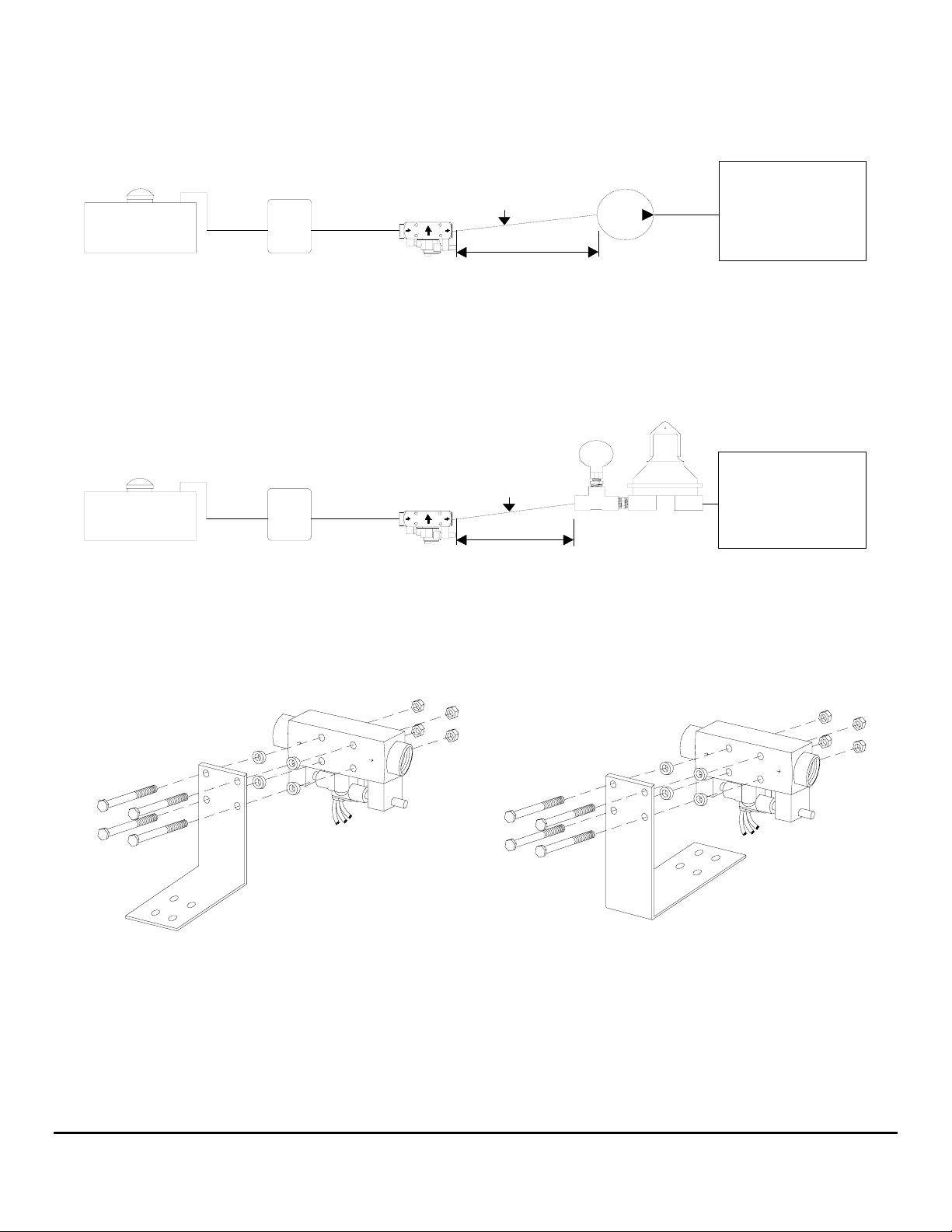
FUEL TANK
High-Flow Gasoline Fuel Flow Schematics
Vane, Gear, Gear-Rotor
Electric
Fuel Pump
Pulsation
Damper
Engine Driven
(Carbureted Inboards and I/O's)
FUEL
FILTER
233
Flow Sensor
1" to 2" Minimum
Vertical Rise
12" Minimum Distance:
A-1 Fabric Braid
Flexible Fuel Line Preferred
(EFI & Carburetor Engines)
ENGINE
Diaphragm Fuel Pump
FUEL TANK
FUEL
FILTER
233
Flow Sensor
Flexible Fuel Line Preferred
1" to 2" Minimum
Vertical Rise
12" Minimum Distance:
A-1 Fabric Braid
ENGINE
High-Flow Sensor Bracket Assembly
2/15/2007 7000-036-00M
FloScan Instrument Company, Inc. Tel: (206) 524-6625 Fax: (206) 523-4961
3016 NE Blakeley Street, Seattle, WA 98105 Email: [email protected] Http://www.floscan.com
Page 14
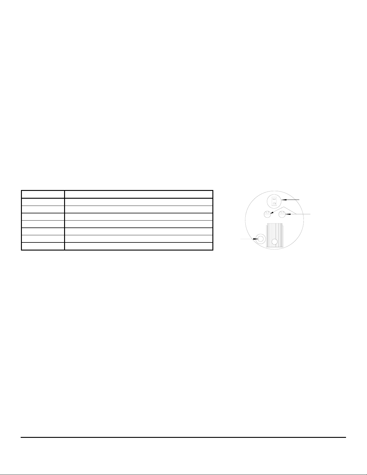
WIRING
TwinScan Gas 3” GPH Instrument Only
CAUTION: To avoid electrical shorts and possible fire, turn OFF the power to the instrument panel until installation is complete.
Please Note: The pointer is accurate only when gauge is energized. The pointer may stop at any position when power is OFF and is
not indicative of a faulty gauge.
This instrument fits in a standard 3 3/8” tachometer hole. The analog needles show the PORT and STARBOARD fuel flow rates of
each engine and the totalizer shows the total consumption of both engines. Fuel consumption is stored in non-volatile RAM and does
not require power to retain its memory. Resetting the totalizer is done with an external switch (not supplied). An excellent choice is a
momentary on (normally open) switch. You can also use a single throw, single pole (SPST) switch.
Wiring
Use No. 18 AWG mufti-strand wire, the included butt splices and self-sealing heat shrink to make all connections. Alternate
installation: Use insulated ring tongue connectors and a terminal strip.
Important: Protect wires from damage caused by sharp edges, moving and hot engine parts. Cable tie and support all wire runs for
safety.
Wire Color Function
RED/WHITE PORT Instrument & flow sensor +12 VDC Power
RED STARBOARD Instrument & flow sensor+12 VDC Power
BLACK Battery Ground (Instrument & flow sensor ground)
WHITE PORT Flow Sensor Input
BROWN STARBOARD Flow Sensor Input
GREEN Totalizer Reset Switch
WHITE/RED Pulse Output to Tachometer/MPG Switch if Installed
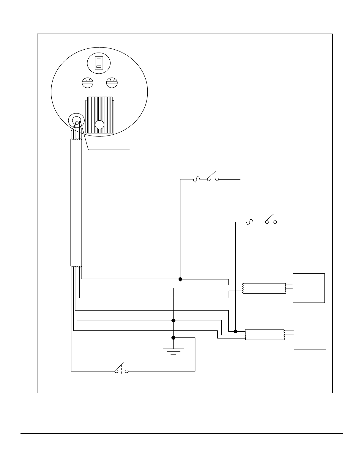
1. Connect the RED/WHITE wire to the “power on” side of the PORT ignition switch.
2. Connect the RED wire to the “power on” side of the STARBOARD ignition switch. In multiple gauge installations, join all the
RED/WHITE wires together and run a single wire to the keyed terminal of the PORT ignition switch. Do the same for the RED
wires on the STARBOARD side.
3. Connect the BLACK wire of the gauge to the BLACK wire(s) at the flow sensor(s). Run a BLACK wire to the negative battery bus
from this point. This instrument requires a single point ground system. Connecting the gauge to a ground at the instrument panel
and the flow sensor(s) to a different ground can introduce noise and affect the accuracy of the instrument.
4. Connect the WHITE wire of the instrument to the WHITE wire of the PORT flow sensor.
5. Connect the BROWN wire of the instrument to the WHITE wire of the STARBOARD flow sensor.
6. Connect the GREEN wire to one of the terminals of a single pole, single throw (SPST) or momentary on (normally open) switch.
Run a BLACK wire from the other terminal of the switch to the Instrument BLACK wire (ground.) Totalizer reset switch OPEN Normal operation , Totalizer reset switch CLOSED - Reset mode.
®
To ensure years of trouble free operation of your new TwinScan® Instrument
please read all of these instructions carefully before beginning your installation.
Back of Instrument
Dial Lamp
0 0
Black Switch Red Switch
Wires
Calibration Knobs
5/15/2002 1000-108-00E
FloScan Instrument Company, Inc. Tel: (206) 524-6625 Fax: (206) 523-4961
3016 NE Blakeley Street, Seattle, WA 98105 Email: [email protected] Http://www.floscan.com
Page 15
Back of GPH Instrument
0 0
Black Switch Red Switch
E
L
B
A
C
RED/WHITE
WHITE
RED
BLACK
BROWN
WHITE/RED
(This wire is used when a tach is installed)
Port Engine
key switch
1/2 amp fuse
RED
BLACK
WHITE
RED
BLACK
WHITE
+ 12 VDC
1/2 amp fuse
CABLE
CABLE
Starboard Engine
key switch
R
B
W
R
B
W
+ 12 VDC
PORT
Flow
Sensor
STARBOARD
Flow
Sensor
Battery (-) buss
GREEN
Totalizer Reset Switch
BLACK
* Do not use Back-lit, or Illuminated switches
5/15/2002 1000-108-00E
FloScan Instrument Company, Inc. Tel: (206) 524-6625 Fax: (206) 523-4961
3016 NE Blakeley Street, Seattle, WA 98105 Email: [email protected] Http://www.floscan.com
Page 16
CALIBRATION
TwinScan® 3” GPH Instrument
Gasoline and Diesel Engines
To ensure years of trouble free operation of your new GPH Meter,
please read all of these instructions carefully before beginning your installation.
Calibration and flow sensor selection of your TwinScan
back of the instrument. The RED switch is used for sensor type and pointer damping selection; the BLACK switch is used to calibrate
your instrument. It is critical that you set the sensor selection switch correctly. Before re-calibr a ting your instrument, note the current
position of the switch and check the calibration table for the correct flow sensor selection. Changing the totalizer calibration also
changes the analog needle calibration.
Re-calibration is required only if you find your totalizer reading to be more than 2% different from the actual fuel put into the tank.
Various things such as the attitude of the boat in the water, the amount of the fill up, and how full the tank is filled affect accuracy.
The larger the amount of fuel you base calibration on, the more accurate your system will be.
To check the calibration:
1. Fill the tank(s) and reset the totalizer to zero.
2. Operate the boat in a normal manner until you would ordinarily refuel.
3. Fill the tank(s) as close to the same level as possible. Check the amount of fuel the tank actually took as well as the amount the
totalizer shows you used. In most cases, these two amounts are within 2% of each other and no additional calibration is
required.
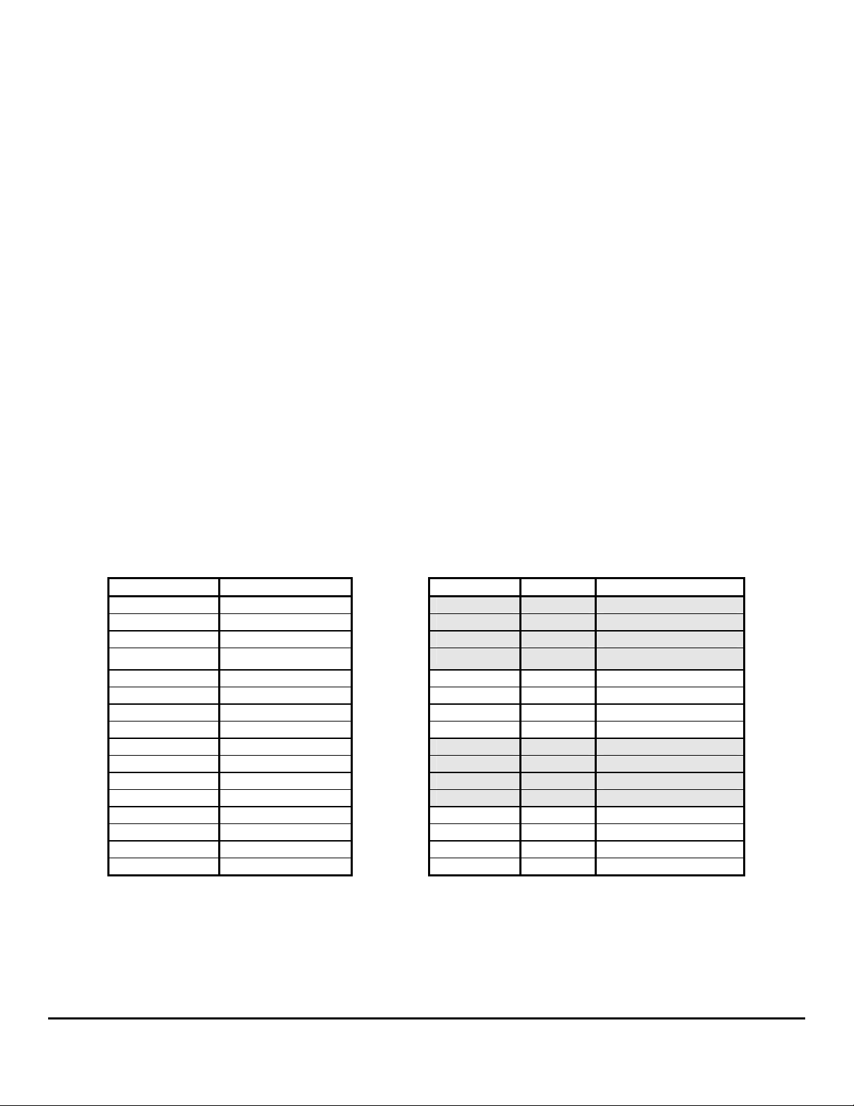
4. To change the calibration, rotate the BLACK switch on the back of the instrument until the totalizer reads as close to your
actual fill up as possible. If your reading is off by more than you can calibrate, go to the troubleshooting guide.
BLACK Switch Effect to Totalizer
0 No Change 0 20B Light meter damping
1 +2% 1 20B Heavy meter damping
2 +4% 2 20B Light meter damping
3 +6% 3 20B Light meter damping
4 +8% 4 231 Light meter damping
5 +10% 5 231 Heavy meter damping
6 -20% 6 231 Light meter damping
7 -18% 7 231 Light meter damping
8 -16% 8 233C Light meter damping
9 -14% 9 233C Heavy meter damping
A -12% A 233C Light meter damping
B -10% B 233C Light meter damping
C -8% C w/diesel* Light meter damping
D -6% D w/diesel* Heavy meter damping
E -4% E w/diesel* Light meter damping
F -2% F w/diesel* Light meter damping
*TwinScan + MFI combination
®
3” GPH Instrument is done with the sixteen position rotary switches on the
RED Switch Sensor Results
9/19/2003 1000-148-00E
FloScan Instrument Company, Inc. Tel: (206) 524-6625 Fax: (206) 523-4961
3016 NE Blakeley Street, Seattle, WA 98105 Email: [email protected] Http://www.floscan.com
Page 17

9/19/2003 1000-148-00E
FloScan Instrument Company, Inc. Tel: (206) 524-6625 Fax: (206) 523-4961
3016 NE Blakeley Street, Seattle, WA 98105 Email: [email protected] Http://www.floscan.com
Page 18

TROUBLESHOOTING
TwinScan® 3” Instrument - Gallons Per Hour (LCD)
BEFORE CALLING FOR ASSISTANCE, COMPLETE THESE TROUBLESHOOTING CHECKS AND RECORD YOUR
FINDINGS. TECHNICAL SUPPORT REQUIRES THIS INFORMATION BEFORE A RETURN AUTHORIZATION WILL BE
ISSUED. IT TAKES ABOUT 20 MINUTES AND IS VERY IMPORTANT IN ANALYZING SYSTEM PROBLEMS.
Before starting, record instrument model number and switch settings.
MODEL # _____________________ SERIAL # ____________
RED SWITCH POSITION __________ BLACK SWITCH POSITION _________
Perform the Instrument Diagnostic & Duty Cycle Tests outlined in Sections I & II First. Record your findings.
I. INSTRUMENT DIAGNOSTIC SELF-TEST
• Secure power to the Red, and Red/White wires, (Turn both key switches OFF).
• Turn power on, (Either to one or both switches). At start-up, the instrument automatically performs a, “Self-test”.
• Verify that the pointer’s back-lighting glows Red, and that the LCD back-light is glowing Green.
• Observe that the pointers smoothly sweep to near full scale, (Slightly above or below) then smoothly drop back to zero.
The LCD display shows the following numbers and letters in sequence. These are examples, actual readings may vary. Switch settings
and configurations are shown on the LCD as, “0123456789AbCdEF”.
8.8.8.8 LCD segment and back-lighting check.
1.21 Software version number.
F 3 Red, (Port) and Black (Starboard) switch settings.
- - 34 Internal configuration (scale range, units, etc.)
Blank
123.4 Current total gallons or total liters, (Indicates normal operation).
• Record the software version __________ and switch settings _____ _____. FloScan Technical Support will ask for these.
The self-test verifies adequate power, a good ground, that the pointers move, and the LCD display is working.
If the self-test fails, the LCD shows, “PO” plus a two-digit number code. The pointers also show the error number as a, “Blink Code”.
Sitting near center scale the pointers will twitch upwards, showing a numeric value. For Po23 the pointers twitch twice, pause for a
moment, and then twitch three times. After a long wait the twitching resumes. This continues until power is secured. If the self-test
fails, verify that supply voltage is at least 10 VDC. If voltage drops below 10V, the self-test may fail.
II. DUTY CYCLE TEST
• Start both engines and run at idle.
• Close and open the RESET switch twice within 0.6 seconds—like double-clicking a computer mouse.
• The LCD will show dcy when it’s in duty cycle check mode.
• With the display showing dcy the pointers should remain steady and in the middle third of their scales.
• At very low flow rates, the pointers track the on/off signal from each sensor and will wiggle.
• Increase engine rpm until the pointers are steady.
• Steady readings with occasional, “Hick-ups” may indicate air or vapor bubbles passing through the sender.
• “Double-click” the RESET switch to return to the normal fuel flow display mode.
8/30/2004 1000-204-00C
FloScan Instrument Company, Inc. Tel: (206) 524-6625 Fax: (206) 523-4961
3016 NE Blakeley Street, Seattle, WA 98105 Email: [email protected] Http://www.floscan.com
Page 19
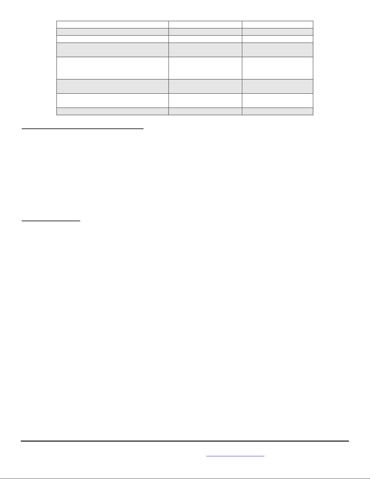
FAULT PROBABLE CAUSE SEE SECTION:
Blank LCD Display Wiring Section III
No back-lighting Wiring/bulb failure Section
Low Totalizer Reading, over 10% Calibration Calibration sheet
Sensor orientation/failure Section IV, Install. sheets
High Totalizer Reading, over 10% Incorrect/defective sensor Section IV
Incorrect switch settings Calibration sheet
Suction leak Section VII
Fluctuating GPH Readings Suction leak Section VII
Low RPM operation Section X
No GPH or Totalizer Reading Wiring/Instrument failure Section I, II, III, and V
Sensor orientation/failure Section IV, Install. sheet
Wire Harness Continuity Test Section V
III. SUPPLY VOLTAGE and GROUND TEST
• Measure voltage between the Starboard RED power wire, and the BLACK Instrument ground wire. __________VDC
• Measure voltage between the Port RED/WHITE power wire, and the BLACK Instrument ground wire. __________VDC
These readings should be approximately 12 - 14 VDC, but not lower than 10 VDC.
• If 12 VDC is not present, measure between the RED, or RED/WHITE power wire and a known good ground
in the instrument panel. If you measure 12 to 14 VDC, there may be an instrument ground problem. __________VDC
• If 12 to 14 VDC is not present check wiring, switches, fuse, and the 12 VDC power source.
IV. SENSOR(S) TEST
1. With your voltmeter set to a DC scale greater than 14 volts, measure between the RED (+12VDC) and
BLACK (Instrument ground) wires. With engine idling, measure and record the voltage reading. ___________VDC
2. Move the voltmeters’ negative lead to the WHITE (Signal) wire. With engine idling, measure and record
the voltage reading. Readings between 4 and 10 VDC usually indicate a good sensor. ___________VDC
3. Stop the engine while observing the voltmeter. Readings should fluctuate between a high of 9 to 12 VDC,
and a low of 0 to 4 VDC as the sensors’ turbine slows to a stop. ___________VDC
NOTE: This may not be seen on a digital voltmeter.
4. Move the voltmeters’ negative lead to the BROWN (Signal) wire. With engine idling, measure and record
the voltage reading. Readings between 4 and 10 VDC usually indicate a good sensor. ___________VDC
5. Stop the engine and observe the voltmeter. Voltage readings should fluctuate between a high of 9 to 12
VDC, and a low of 0 to 4 VDC as the Sensors’ turbine slows to a stop.
NOTE: This may not be seen with a digital voltmeter.
6. The Sensor may be defective if voltage readings in steps 3 & 5 remain constant while the engine is
stopping.
7. On twin engine systems, try swapping the Brown & White signal wires. Observe the Instrument and see if the
problem shifts sides, or remains on the same side.
8/30/2004 1000-204-00C
FloScan Instrument Company, Inc. Tel: (206) 524-6625 Fax: (206) 523-4961
3016 NE Blakeley Street, Seattle, WA 98105 Email: [email protected] Http://www.floscan.com
Page 20

• The Sensor(s) may be defective if voltage readings in steps 3 & 5 remain constant.
• If signal voltages in steps 3 & 5 are ok, go to the backside of the Instrument. With engine(s) running, measure and record voltage
readings across the Red/White & White, (Port Sensor) and Red & Brown, (Starboard Sensor) signal wires. These voltage readings
should match the Sensor’ readings. This verifies that the Sensors’ signal output is reaching the Instrument. If not there is a wiring
problem.
V. CONTINUITY TEST
1. Continuity testing requires access to the back of the Instrument and an Ohmmeter. It verifies that wires are not broken, shorted
to ground, another wire, or to power. Before starting, secure all power. You will be testing th e WHITE, BROWN, and BLACK
wires.
2. Disconnect the WHITE and BLACK wire harness conductors from the WHITE and BLACK Port Sensor
& Instrument wires. Connect a jumper from the WHITE wiring harness conductor to a known good ground.
At the Instrument, connect an Ohmmeter lead to its’ WHITE wiring harness conduc tor. Connect the other ____________
Ohmmeter Lead to a known, good ground. The Ohmmeter should read approximately 0.1 to 3 Ω. (Ohm Reading)
Connect a jumper from the Black wiring harness conducto r to a known good ground. At the Instrument
connect an Ohmmeter lead to its’ Black wiring harness conductor. Connect the other Ohmmeter Lead to ____________
a known, good ground. The Ohmmeter should read approximately 0.1 to 3 Ω. (Ohm Reading)
3. Disconnect the Brown and BLACK wire harness conductors from the WHITE and BLACK Starboard Sensor
& Instrument wires. Connect a jumper from the BROWN wiring harness conductor to a known good ground.
At the Instrument, connect an Ohmmeter lead to its’ BROWN wiring harness conductor. Connect the other ____________
Ohmmeter Lead to a known, good ground. The Ohmmeter should read approximately 0.1 to 3 Ω. (Ohm Reading)
Connect a jumper from the Black wiring harness conducto r to a known good ground. At the Instrument
connect an Ohmmeter lead to its’ Black wiring harness conductor. Connect the other Ohmmeter Lead to ____________
a known, good ground. The Ohmmeter should read approximately 0.1 to 3 Ω. (Ohm Reading)
VI. PULSATION PROBLEMS
A stiff anti-siphon valve, sticking carburetor float or miss-plumbed Pulsation Damper(s) can cause fluctuating GPH readings. These are
most pronounced at low Rpm’s and tend to disappear around mid throttle. They are annoying, but won’t affect totalizer accuracy. To
eliminate, repair or replace any defective parts, or re-plumb dampers according to the Fuel Flow Schematic Instructions.
VII. FINDING FUEL SYSTEM VACUUM LEAKS
Fluctuating GPH and High Totalizer Readings are usually caused by a small vacuum leak between the fuel tank and fuel pump inlet.
Fluctuations tend to be between 2 and 4 GPH. These vacuum leaks also affect totalizer accuracy, causing it to read 15 to 100% high.
Larger leaks produce greater fluctuations and higher readings. They generally do not affect engine performance.
Finding suction leaks can be time-consuming. When approached properly, they can usually be found and repaired quickly. Two
common places for suction leaks to occur are at the primary fuel filter - water separator, and/or a loose valve stem packing nut.
Remove the filter housing and coat all o-rings, gaskets and sealing surfaces with a medium to heavy grease, (Do not use oil) and
reassemble. Grease all valve stem packings and gently tighten gland nuts. Don’t over tighten, valve handles should turn freely.
Tighten all hose clamps and compression fittings. Don’t over tighten. Run th e engine for 5 to 10 minutes observ ing GPH readings. If
you’ve found the problem, fluctuations should be reduced to less than ½ GPH.
8/30/2004 1000-204-00C
FloScan Instrument Company, Inc. Tel: (206) 524-6625 Fax: (206) 523-4961
3016 NE Blakeley Street, Seattle, WA 98105 Email: [email protected] Http://www.floscan.com
Page 21

If the problem persists, temporarily install a clear piece of fuel resistant hose downstream of the forward flow sensor. Run the engine
and watch for a stream of small bubbles in the clear hose, or an occasional larger bubble. Sometimes shining a light through the hose
makes bubbles easier to see.
Observe the clear hose while shaking the fuel lines. If the bubble stream continually increases or decreases you’ve found the leak area.
Repair or replace as needed. If this occurs one-time, you probably dislodged some trapped air.
If the leak hasn’t been found, the last step is to inspect each pipe joint. Thread sealant should be visible around each joint. If not, that
joint is suspect and must be resealed. After resealing run the engine for a few minutes to purge any remaining air. There should now
be bubble free fuel running through the clear hose. If bubbles are still present a leak was missed. Recheck your work. After all the
leaks are stopped, remove the clear hose.
VIII. FUEL FILTERS
A dirty fuel filter, or one that is too fine (1-25 micron) will draw vapor bubbles out of the fuel, causing fluctuations and high readings.
Replace it with a new 30-micron or coarser filter.
IX. FLOW SENSOR ORIENTATION
Sensor orientation is critical for proper operation. All Sensors have their inlet and outlet ports clearly marked (IN / OUT or Î Î).
This identifies fuel flow direction. The Sensor must be, “Plumbed” correctly for it to operate properly. There is an addition al single
arrow on the Sensor body. It is crucial that this single arrow points up Ï.
X. LOW RPM OPERATION
At idle, under a no load condition, it is common for GPH readings to fluctuate slightly.
This concludes system testing. If problems with your system persist,
contact FloScan Technical Support with testing results.
8/30/2004 1000-204-00C
FloScan Instrument Company, Inc. Tel: (206) 524-6625 Fax: (206) 523-4961
3016 NE Blakeley Street, Seattle, WA 98105 Email: [email protected] Http://www.floscan.com
 Loading...