

Page 1
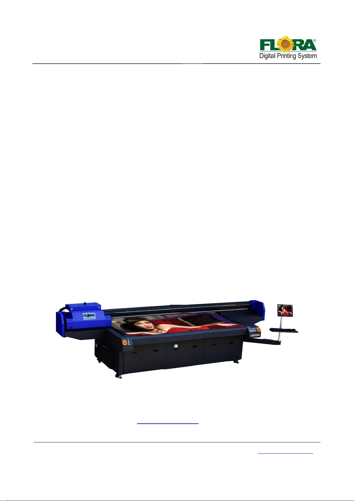
PP2512UV
User's Guide
ADD:GuanlanHi‐techIndustryPark,HuanguanSouthRoad,Baoan
District,Shenzhen,ChinaP.C:518110
TEL:+86‐755‐27521666
FAX+86‐755‐27521866
Victor Xu Page 1 12 Jan. 2011
Copyright 2011 © Shenzhen Runtianzhi Image Technology, Co., Ltd.
http://www.floradigital.com
Page 2

Table of Contents
LORADIGITALPRINTINGSYSTEM..........................................................................................................................................5
F
DISCLAIMER............................................................................................................................... ........................................5
MANUALUSAGECONDITIONSANDLIMITATIONS.......................................................................................................................5
CONTENTSOFPACKAGE........................................................................................................................................................5
PRINTERINTRODUCTION.......................................................................................................................................................6
TABLE1GENERALFEATURES.............................................................................................................................................6
TABLE2TECHNICALSPECIFICATION......................................................................................................................................6
TABLE3FLORAPP2512UVPRINTERMODELCODING...........................................................................................................7
ABOUTTHEMANUAL...........................................................................................................................................................7
CHAPTER1‐SAFETYOPERATINGINSTRUCTIONS.....................................................................................................................8
1.1 BriefIntroduction.............................................................................................................................................8
1.2 SafetyInformation...........................................................................................................................................8
1.2.1 SolventandInkProperties.......................................................................................................................................8
1.2.2 DangerofFireandExplosion...................................................................................................................................8
1.2.3 Anti‐ultravioletradiation..........................................................................................................................................8
1.2.4 ProperVentil ationandExhaustSystem...................................................................................................................8
1.2.5 Inkandsolventspillage,apotentialriskofFireandexplosion................................................................................9
1.2.6 Highvoltagemayshockpeopleortriggerafire.......................................................................................................9
1.2.7 Printingmediarollsarebulkyandveryheavy.........................................................................................................9
1.3 Fireproofing.....................................................................................................................................................9
1.4 ExhaustSystem................................................................................................................................................9
1.5 HandlingPrecautions.......................................................................................................................................9
1.5.1 PowerSupply...........................................................................................................................................................9
1.5.2 Printer....................................................................................................................................................................10
1.6 RegularInspectionandMaintenance............................................................................................................10
1.7 Consumables..................................................................................................................................................10
CHAPTER2‐PRE‐INSTALL................................................................................................................................................11
2.1 GettingStarted..............................................................................................................................................11
2.2 OperatingConditions.....................................................................................................................................11
2.2.1 InstallationSpace...................................................................................................................................................11
2.2.2 EnvironmentConditions........................................................................................................................................11
2.2.2.1 Operatingtemperatureandhumiditylevels..........................................................................................................11
2.2.2.2 Placeswheretheprintermustnotbeinstalled.....................................................................................................11
2.3 Consumables..................................................................................................................................................11
2.3.1 AvailableMediaTyp es............................................................................................................................................12
CHAPTER3‐EXTERNALVIEWS,PARTNAMESANDFUNCTIONS................................................................................................13
3.1 PrintHeadCarriageAssembly.......................................................................................................................13
3.1.1 PrintheadsPlatform..............................................................................................................................................13
3.1.2 AutoDetectMediaThicknessSensor.....................................................................................................................14
3.1.3 UVLampAssembly................................................................................................................................................14
3.1.4 PressureSensor......................................................................................................................................................15
3.2 MaintenanceStation.....................................................................................................................................15
3.3 RailguideandBeamAssembly......................................................................................................................16
3.3.1 X‐axisRailguideandBeam....................................................................................................................................16
3.3.2 Y‐axisRailguide......................................................................................................................................................16
3.4 ControlPanel.................................................................................................................................................17
Victor Xu Page 2 12 Jan. 2011
Copyright 2011 © Shenzhen Runtianzhi Image Technology, Co., Ltd.
http://www.floradigital.com
Page 3

3.4.1 MaintenanceControlPanel....................................................................................................................................17
3.4.2 MovementandUVlampControlPanel..................................................................................................................17
3.4.3 MainCircuitBreaker..............................................................................................................................................18
3.4.4 StartandE‐StopButton.........................................................................................................................................18
3.4.5 VacuumChamberControlValves ...........................................................................................................................18
3.5 ElectricalfixationShelf...................................................................................................................................19
3.6 InkSupplyControlCompartment...................................................................................................................19
3.7 InkBottleCompartment................................................................................................................................19
3.8 UVPowerSupply&VacuumPump................................................................................................................20
CHAPTER4‐WORKINGSYSTEMOFFLORAPP2512UV..........................................................................................................21
4.1 BriefIntroduction...........................................................................................................................................21
4.2 TheKonicaMinoltaPrintheadAssembly.......................................................................................................21
4.3 PCBboards.....................................................................................................................................................22
4.4 Movingsystem...............................................................................................................................................27
4.4.1 X‐axis(Carriagemovingsystem).............................................................................................................................27
4.4.1.1 ServoDriverPack...................................................................................................................................................27
4.4.1.2 Servomotor...........................................................................................................................................................28
4.4.1.3 Rasterreaderandstrip...........................................................................................................................................28
4.4.1.4 Limitedswitch............................................................................................................................... .........................28
4.4.1.5 Anti‐crashSensor............................................................................................................................... ....................29
4.4.2 Y‐axis(Beammovingsystem).................................................................................................................................29
4.4.2.1 ServoDriverPack...................................................................................................................................................29
4.4.2.2 Servomotor...........................................................................................................................................................29
4.4.2.3 Limitedswitchandopticalswitch..........................................................................................................................29
4.4.3 Z‐axis(Autoheightadjustingsystem).....................................................................................................................30
4.4.3.1 Stepperdriver&motor..........................................................................................................................................30
4.4.3.2 Rasterreaderandstrip...........................................................................................................................................31
4.4.3.3 Detectingsensor....................................................................................................................................................31
4.4.3.4 Limitedswitch............................................................................................................................... .........................31
4.5 Inksupply&negativepressuresystem...........................................................................................................32
4.5.1 Inksupplysystem...................................................................................................................................................32
4.5.2 Whiteinkcirculationsystem..................................................................................................................................33
4.5.3 Inkalarmsystem....................................................................................................................................................33
4.5.4 Negativepressuresystem......................................................................................................................................33
4.5.5 Overflowprotectionsystem...................................................................................................................................34
4.5.6 Externalpowersystem...........................................................................................................................................34
4.5.7 Individualpurgesystem.........................................................................................................................................35
4.6 Vacuumsystem..............................................................................................................................................35
4.6.1 VariableVacuumControlSystem...........................................................................................................................35
4.6.2 VacuumChamber...................................................................................................................................................35
4.7 Curingsystem.................................................................................................................................................35
4.7.1 Overheatprotector................................................................................................................................................35
4.7.2 Intelligentcuringmode..........................................................................................................................................36
4.7.3 Twolevelpower.....................................................................................................................................................36
4.7.4 UVlampauto‐shutofffunction..............................................................................................................................36
4.8 Auto‐cleaningsystem.....................................................................................................................................36
4.9 AutomaticRegistrationPinSystem................................................................................................................37
CHAPTER5–INSTALLATIONMANUALOFFLORAPP2512UV....................................................................................................38
5.1 Pre‐InstallationRequirement.........................................................................................................................38
5.2 MachinePre‐Installation................................................................................................................................38
5.3 Installationofsoftware..................................................................................................................................38
5.3.1 InstallationProcedureofPhotoPRINTServerFloraEdition6.1v2..........................................................................38
5.3.2 Installationprocedureoffloradriver.....................................................................................................................41
Victor Xu Page 3 12 Jan. 2011
Copyright 2011 © Shenzhen Runtianzhi Image Technology, Co., Ltd.
http://www.floradigital.com
Page 4

5.3.3 Addsetup...............................................................................................................................................................42
5.4 Installprintheads..........................................................................................................................................42
5.5 InkandSolventPreparation...........................................................................................................................45
5.6 Test print........................................................................................................................................................45
5.5.1 Test printtoolbar...................................................................................................................................................45
5.5.2 Setparameter........................................................................................................................................................45
5.5.3 Printheadalignment..............................................................................................................................................47
5.5.3.1 MechanicalAlignment(Y‐Align).............................................................................................................................47
5.5.3.2 InternalAlignment.................................................................................................................................................49
5.5.3.3 RightAlign..............................................................................................................................................................51
5.5.3.4 PrintheadXAlign...................................................................................................................................................52
5.5.3.5 StepAlign............................................................................................................................... ................................53
CHAPTER6‐OPERATIONMANUALOFFLORA PP2512UV......................................................................................................55
6.1 BriefIntroduction...........................................................................................................................................55
6.2 Starting‐upActivities......................................................................................................................................55
6.3 PrintheadJettingCheck................................................................................................................................55
6.4 OperationalapproachofPhotoPrint..............................................................................................................55
6.4.1 PhotoPrintJobFolder............................................................................................................................................55
6.4.2 EditingtheImage...................................................................................................................................................56
6.4.3 WorkFlowTag........................................................................................................................................................57
6.4.4 ColorManagementTag..........................................................................................................................................57
6.4.5 Test PrintTag..........................................................................................................................................................58
6.4.6 AdvanceButton......................................................................................................................................................58
6.5 Shut‐offprocedure.........................................................................................................................................62
6.5.1 Over‐nightprotection.............................................................................................................................................62
6.5.2 Longtermprotection.............................................................................................................................................62
CHAPTER7SERVICEANDMAINTENANCEMANUALOFFLORAPP2512UV................................................................................64
7.1 BriefIntroduction...........................................................................................................................................64
7.2 Maintenanceofprintheads...........................................................................................................................64
7.2.1 FlushingaSelectedPrinthead...............................................................................................................................64
7.2.2 ReplacingthePrinthead........................................................................................................................................64
7.3 MaintenanceofInkSupplyandVacuumLineSystem....................................................................................64
7.3.1 ChangingDefectiveInkPumpandFilter................................................................................................................64
7.3.2 ChangingDefectiveAirPump.................................................................................................................................65
7.4 MaintenanceofPrinterMovingParts............................................................................................................65
7.4.1 MaintenanceofX‐axis............................................................................................................................................65
7.4.2 MaintenanceofY‐axis............................................................................................................................................66
7.4.3 MaintenanceofZ‐axis............................................................................................................................... .............67
7.4.4 Maintenanceofauto‐cleansystem........................................................................................................................67
CHAPTER8‐APPENDICES................................................................................................................................................68
AppendixAMaterialSafetyDataSheetforUVInks...........................................................................................68
AppendixBPreventiveMaintenanceChecklist...................................................................................................72
AppendixCTroubleshootingGuide....................................................................................................................73
AppendixDGlossary...........................................................................................................................................76
Victor Xu Page 4 12 Jan. 2011
Copyright 2011 © Shenzhen Runtianzhi Image Technology, Co., Ltd.
http://www.floradigital.com
Page 5

Flora Digital Printing System
Flora Digital Printing System, reserves the right to make changes without prior notice to the specifications
and materials contained herein and shall not be responsible for any damages (including consequential)
caused by reliance on the materials presented, including but not limited to typographical, arithmetic, or listing
errors.
This equipment has been tested and found to comply with the limits for a class A digital device. Pursuant to
part 15 of the FCC Rules, these limits are designed to provide reasonable protection against harmful
interference when the equipment is operated in a commercial environment.
This equipment generates, uses, and can radiate radio frequency energy and used in accordance with the
instruction manual, may cause harmful interference to radio communications. Operation of this equipment in
a residential area is likely to cause harmful interference, in which the user will be required to correct the
interference at his own expense.
This printer is a color inkjet printer that uses a UV-curable ink, supports up to 1800mm of media width, and
has a built-in USB interface.
This manual, the PP 2512UV User's Guide, describes the features of the printer, names of components,
information needed before use, and basic operations, such as how to turn the power ON and OFF, loading
and setting of the media and loading of ink.
The following items should be read before proceeding to Section 1;
− Contents of the package
− Safety precautions
− Handling precautions
− Notion
Notice: Read these items to use the printer safely and properly. Keep this manual in a place where you can
quickly access it any time.
Disclaimer
This is an alpha release of the User's Guide for Flora PP 2512UV printer. We have made every effort to
guarantee the accuracy and integrity of the information in this manual. If you find some errors or omissions,
please bring them to our attention so we can check and correct them accordingly.
This manual can be used as a reference for operation and routine maintenance of the Flora PP 2512UV
printers. It can’t be a replacement for the formal training provided by Shenzhen Runtianzhi Image Technology
Co., Ltd, regarding on how to operate the printers properly. Shenzhen Runtianzhi Image Technology Co., Ltd
will not take any responsibility for the consequences of misusing this manual and appendix.
Manual Usage Conditions and Limitations
The manual includes patent information, which belongs to Shenzhen Runtianzhi Image Technology Co., Ltd.,
the purpose of which is to help the authorized customers. Without the written permission from RTZ Company
and the public declaration, any content of this manual should not be used for other purposes.
The text and images are subject to change without prior notice. Any software mentioned in this manual is
provided by permission. Use or copy of these softwares must be according and to follow prior regulations. If
the information in this manual has changed, there will be no further notice unless it is specified.
Contents of Package
The internal printer components, including the options, are installed on the main unit on delivery. The print
heads and extension table assembly are included on a separated box within the main crate.
Victor Xu Page 5 12 Jan. 2011
Copyright 2011 © Shenzhen Runtianzhi Image Technology, Co., Ltd.
http://www.floradigital.com
Page 6
If any parts are missing or damaged, please contact the shop or dealership where you have purchased the
product or the nearest service center.
Printer Introduction
The Flora PP 2512UV printer is a wide format digital printer suitable for small up to medium size business
use. It uses a UV curable ink, which is environment friendly. It provides high productivity and is capable to
replace traditional silkscreen printing. This type of printer is widely used in the fields such as advertisement,
packing, printing, interior decoration, POP board, glass work, flexible packaging, wooden work, printing
circuit board, etc.
Flora PP 2512UV series printers use drop-on-demand and Piezo-electric technology. It can print colorful and
wide image by using the highest 1440x1440 dpi resolution. It can output any size of images with “tile” feature
in the software. Indeed, it is a combination of roll-to-roll and rigid board printer.
Table 1 General Features
Item
No
1
Printing Method Drop-on-demand Piezo-electric
2
No. of colors 8 (CMYKLmLc+White+Varnish)
3
Ink/Varnish type UV curable
4
Ink reservoir capacity (volume) 4 Li/color (refillable while printing is on progress)
5
Outdoor Durability 2 years for Flora UV curable ink
6 Media handling system
D e s c r i p t i o n Specification
Roll-to-Roll, single sheet, Indexing Conveyor Flat
bed with vacuum
Roll-to-roll including paper, vinyl, adhesive back
7 Media types
vinyl, fabrics, banners, PVC, etc and flat rigid
boards including, corrugated foam, Plexiglas,
Sheet metal, sheet film, ceramic tiles, etc.
8 Maximum printing size
2.53 m width
2.53 m x 1.25m for board media
9 Maximum media thickness 100 mm
10 Rip software PhotoPrint V5.3 Flora edition (Windows Xp sp3)
11 Driver software FloraPrint
12 Color management ICC based color , density adjustment curves
13 File format Bitmaps, Tiffs, Jpeg, Postcripts3, Eps, Pdf, etc.
14 Work Flow Rip and Print
15 Warranty 1 year (please consult your local dealer for details)
Table 2 Technical Specification
Item
No
1 Model Flora PP 2512UV
Victor Xu Page 6 12 Jan. 2011
Copyright 2011 © Shenzhen Runtianzhi Image Technology, Co., Ltd.
D e s c r i p t i o n Specification
http://www.floradigital.com
Page 7
2
2 Print Head Binary Drop-on-demand piezo-electric
16 (CMYKLmLc+White+Varnish, 2 print heads/color) or
3 No. of print heads
4 No of colors 4/5/6/7/8
5 Printing resolution option
6 Printing quality option Standard, High and Ultra
7 Printing Speed
8 Media maximum width 2.53 m
PC minimum operating
9
requirement.
11 Operating environment
12 UV lamp power rating 1100 W
13 Room temperature
14 Humidity 40~70%
16 (CMYKLmLc +White) 2 print heads/color and 4 print
heads for White
360x360, 360x1080, 720x720,
720x1440, 1440x1440 dpi
Standard Quality: 54 m
High Quality: 38 m
Ultra Quality 28 m
2
2
/hr
/hr
/hr
3GB RAM, 40Gb HDD, Windows XP Service Pack 3
220VAC/50-60Hz/Single Phase, 2 outlets 25 Amp each.
Distortion: < 0.5%
23~33
ºC
15 Dimensions 4.85m x 2.25m x 1.66m
16 Weight 1200 Kg
Table 3 Flora PP 2512UV Printer Model Coding
Code Explanation
Flora
PP
2512
UV
Brand Name
Flat Bed
maximum width:2500cm, maximum length:1200cm
Ink Type
About the manual
The manual provides the end user all the information related to the machine basic functions, software
installation, machine parameter calibratio n, maintenan ce and troubleshooting of Flora PP 2512UV.
Victor Xu Page 7 12 Jan. 2011
Copyright 2011 © Shenzhen Runtianzhi Image Technology, Co., Ltd.
http://www.floradigital.com
Page 8

V
Chapter 1 - Safety Operating Instructions
1.1 Brief Introduction
This chapter introduces the important safety information. Please read and un derstand the safety
information carefully before operating the printer.
1.2 Safety Information
FLORA printer uses the following chemical substances
• All kinds of printing media
• UV Ink
• Cleaning liquid (UV Flush)
1.2.1 Solvent and Ink Properties
• Solvent and Ink are flammable.
• Eye contact with the ink and solvent will break the cornea and weaken the eyesight.
• Contact lens should not be worn when operating printer or when there is n o proper
ventilation.
• Wear safety glasses and gloves while flushing print heads, ink tu be or moving the
ink bottles or containers.
• Solvent and ink can be irritating to eyes, throat and skin. Inhaling the ink fumes
would result in swoon or other symptoms.
• Solvent vapors are heavier than air and may flow and gather in low spot.
This caution symbol represents danger. If this sign is ignored it
may lead to serious injury or damage to the printer .
1.2.2 Danger of Fire and Explosion
Open flames, heat energy or spark around the printer can trigger fire and explosion.
• No smoking, pilot lights, open flames, stoves, heaters or halogen lights should
be turned on within 5m distance from any edge of the printer.
• No portable spark-producing equipment (st atic, electrical or Mechanical) within
5m distance from any edge of the printer.
1.2.3 Anti-ultraviolet radiation
1.2.4 Proper Ventilation and Exhaust Sy stem
Victor Xu Page 8 12 Jan. 2011
Copyright 2011 © Shenzhen Runtianzhi Image Technology, Co., Ltd.
• Wear UV protection glasses and gloves when operating the machine and
avoid being too closer to UV lights.
• When doing maintenance task or being close to the flatbed machine, U
lights must be shut off or close all UV protection doors.
• The vacuum exhaust system must be functioning before the printer operates.
• Do not ignore this safety warning sign to avoid accumulation of flammable
fumes in the area.
http://www.floradigital.com
Page 9

1.2.5 Ink and solvent spillage, a potential risk of Fire and explosion
1.2.6 High voltage may shock people or trigger a fire
1.2.7 Printing media rolls are bulky and very heavy
1.3 Fireproofing
• Store ink and solvent in proper cabinet for flammable liquid storage.
• Keep ink and solvent containers tightly closed at all times. If a container
has sign of damage/leakage, fix or replace it immediately.
• Clean ink or solvent spillages as soon as possible.
• Only use dry powder, or ca rbon dioxide type of fire extinguishers.
• If there’s no emergency power switch which can shut down all the power,
do not connect the printer to main-power supply.
• When the machine’s power is on, do not open the back cover of machine,
or avoid touching electrical parts.
• The printer or other equipments should be grounded, according to the local
safety electrical connection regulation. The ground volt age should be less
than 3 V.
• Set the machine on smooth ceramic tile or cement ground
• Use specified anti-static floor mat to minimize harmful static build-up.
• Wear hand and foot safety protection gear when loading, unloading and
handling media to avoid serious body injuries.
• Use proper heavy duty handling equipment if available.
Ink and solvent should be clearly labeled and stored in a specific area for flammable liquid and
should be in accordance with local regulations of fireproof and safety standard. Ensure that the
specified fire extinguisher is always available near the storage area and should be cleared from any
obstacle in case of emergency.
1.4 Exhaust System
The printing area should be equipped with sufficient exhaust system. The exhaust should be
installed in such a way build up of fumes is minimized. Best location for the exhaust should be at lowest
level, this way the fumes build-up is minimized. Solvent fumes are heavier than air, so fumes build-up
concentrates on the lower level of the room.
Electrical installations inside the printing area must be in accordance
with local Electrical Safety Regulation
1.5 Handling Precautions
1.5.1 Power Supply
1. Install the printer near an easily accessible electrical outlet.
2. Do not provide power to the printer through the same power line as for other noise
generating devices such as motors.
3. Use a power supply matched with the printer specifica t ion.
4. Connect the power cable directly to an electrical outlet. Do not plug several devices into
Victor Xu Page 9 12 Jan. 2011
Copyright 2011 © Shenzhen Runtianzhi Image Technology, Co., Ltd.
http://www.floradigital.com
Page 10

one electrical outlet.
1.5.2 Printer
1. Do not place anything on top of the printer.
2. Do not rest you elbows on the printer.
3. Open and close the top cover gently from the front of the printer with both hands.
4. Before connecting or disconnecting the interface connector, turn the printer OFF.
5. Do not clean the surface of the cover with benzene or paint thinner. The coating may
come off or deteriorate. Wipe the cover with a soft cloth, if the cover is very dirty, use a
cloth moistened with a neutral detergent.
6. Do not touch the ink jet head surface.
1.6 Regular Inspection and Maintenance
The following regular inspection and maintenance must be performed in terms of characte ristics
of the UV-curable ink:
1. Clean the carriage unit and the flat table conveyor surface every day.
2. Make sure that the carriage covers are always replaced.
3. Perform ink supply circuit and print head cleaning when leaving the printer for a long time (2
weeks or more with no power).
4. Perform head cleaning after leaving the printer idle for a long time.
5. Shut off the UV lamp whenever the printer is not in use.
1.7 Consumables
1. Always use the recommended consumables (printing media, ink, ink filters). Failure to follow
this instruction may cause poor printing quality and breakdown.
2. Do not use ink past the expiration date as this may cause a print head breakdown and poor
printing quality.
3. Put a used ink bottle into a plastic bag and dispose of it as an industrial waste. Observe local
regulations for disposal of waste ink bottles.
4. Avoid spilling ink into your skin or clothes. Wash any ink off immediately with soapy water.
5. Check the waste ink container everyday so as not to permit waste ink to leak from you printer.
6. If the waste ink container is being installed or removed, spre ad a stain preventing sheet so as
not to stain the floor with spilled ink.
7. Store ink in a dark and cool place. Never store the ink in high temperatures or direct sunlight,
doing so may cause the ink to deteriorate.
Victor Xu Page 10 12 Jan. 2011
Copyright 2011 © Shenzhen Runtianzhi Image Technology, Co., Ltd.
http://www.floradigital.com
Page 11

Chapter 2 - Pre-install
2.1 Getting Started
This section provides the necessary information to operate the printer. Familiarize yourself with
the basic of the printer before reading Section 2.
Contents of this section:
− Operating conditions
− Consumables
− External Views, Part Names and Functions
2.2 Operating Conditions
This section describes the operating conditions for the printer.
2.2.1 Installation Space
There must be sufficient space around the printer for the replacement of frequently
used parts, for the output of the printed media and for ventilation. In addition, maintenance
space, shown below, is required to repair the printer or replace compone nts.
2.2.2 Environment Conditions
2.2.2.1 Operating temperature and humidity levels
The printer should be used within the temperature and humidity ranges as shown
below;
Temperature: 20 ºC to 30 ºC
Humidity: 30% to 70%
To obtain better print quality, use the printer within temperature of 20 ºC to 25 ºC.
When the operating temperature is lower than 20 ºC or higher than 40º C,
printing speed is reduced to two-thirds of normal print speed to maintain good
print quality.
2.2.2.2 Places where the printer must not be installed
Do not install the printer in the following places:
A location ne ar a fire
Places exposed to direct sunlight
Places subject to vibration
Places with excessive dust
Places subject to extreme changes in temperature or humidity
Places near an air conditioner or a heater
Places where the printer may get wet
Places near a diazo copier that may generate ammonia gas
Places with poor ventilation
Unstable place
2.3 Consumables
Victor Xu Page 11 12 Jan. 2011
Copyright 2011 © Shenzhen Runtianzhi Image Technology, Co., Ltd.
http://www.floradigital.com
Page 12

2.3.1 Available Media Types
The following types of media are available:
9 Paper
9 Advertising banner
9 PVC
9 Mesh Fabrics
9 Adhesive Vinyl
9 Glass Sheets
9 Ceramics
9 Steel Sheets
9 Acrylic Boards
9 KT Boards
9 PVC Boards
9 Foam Boards
Note: Contact our service center for detail
Victor Xu Page 12 12 Jan. 2011
Copyright 2011 © Shenzhen Runtianzhi Image Technology, Co., Ltd.
http://www.floradigital.com
Page 13
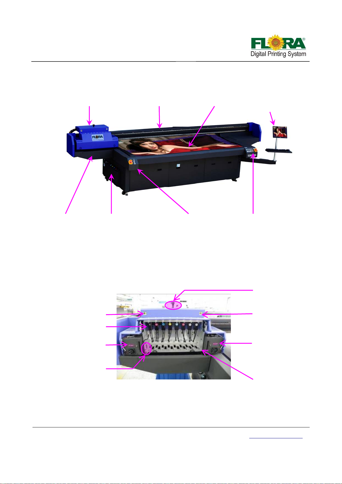
Chapter 3 - External Views, Part Names and Functions
Carriage Assembly
Beam Assembly Flat Bed
Maintenance
Load ink Area
Station
Left Control Panel
Monitor & Key board
Assembly
Right Control Panel
3.1 Print Head Carriage Assembly
The print head carriage assembly houses the print heads, secondary ink tanks, print head
control board, raster reader, negative & positive pressure sensor, carriage height adjustment motor and
the two UV lamps.
Negative pressure
sensor display
Ink tanks
Left UV Lamp
Height adjustment
Assembly
Print Head Carriage Assembly
3.1.1 Print heads Platform
This platform is also called carriage platform, which is serves as print heads fixed frame.
There are two kinds of platform because of different print head configuration.
Height adjust knob
Positive pressure
sensor display
Right UV Lamp
Print heads Platform
Victor Xu Page 13 12 Jan. 2011
Copyright 2011 © Shenzhen Runtianzhi Image Technology, Co., Ltd.
http://www.floradigital.com
Page 14
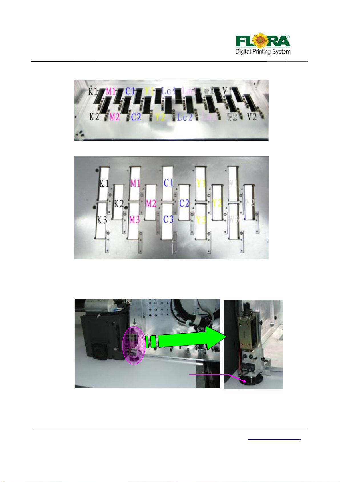
y
Two Rows Platform
Three Rows Platform
3.1.2 Auto Detect Media Thickness Sensor
This mechanism will perform media thickness check every time you send an image for
printing.
3.1.3 UV Lamp Assembly
UV lamp assembly is a device for curing UV ink. The curing mode can be controlled by
Victor Xu Page 14 12 Jan. 2011
Copyright 2011 © Shenzhen Runtianzhi Image Technology, Co., Ltd.
This part will detect the top
surface of the media
Carriage Assembl
Media Height Detector Assembly
http://www.floradigital.com
Page 15

Wi
blad
y
control panel and software.
AC power
Cable
Heat
dissipation
Fans
3.1.4 Pressure Sensor
Left UV Lamp Right UV Lamp
The negative pressure display setting parameters are programmed to control the maximum
positive pressure thereby protecting the print head from excessive pressure.
There are two pressure sensors in total for every printer: one controlling negative pressure,
while the other one controlling positive.
Enlarge View
3.2 Maintenance Station
It is also called print head cleaning system where you do ink purging/ priming then wiping the
excess ink off the print head nozzles.
per
Left UV light
e
reflector
Negative
Pressure Sensor
Carriage Assembly
Maintenance Station
Positive
Pressure Sensor
Waste Tra
Right UV light
reflector
Victor Xu Page 15 12 Jan. 2011
Copyright 2011 © Shenzhen Runtianzhi Image Technology, Co., Ltd.
http://www.floradigital.com
Page 16
V
y
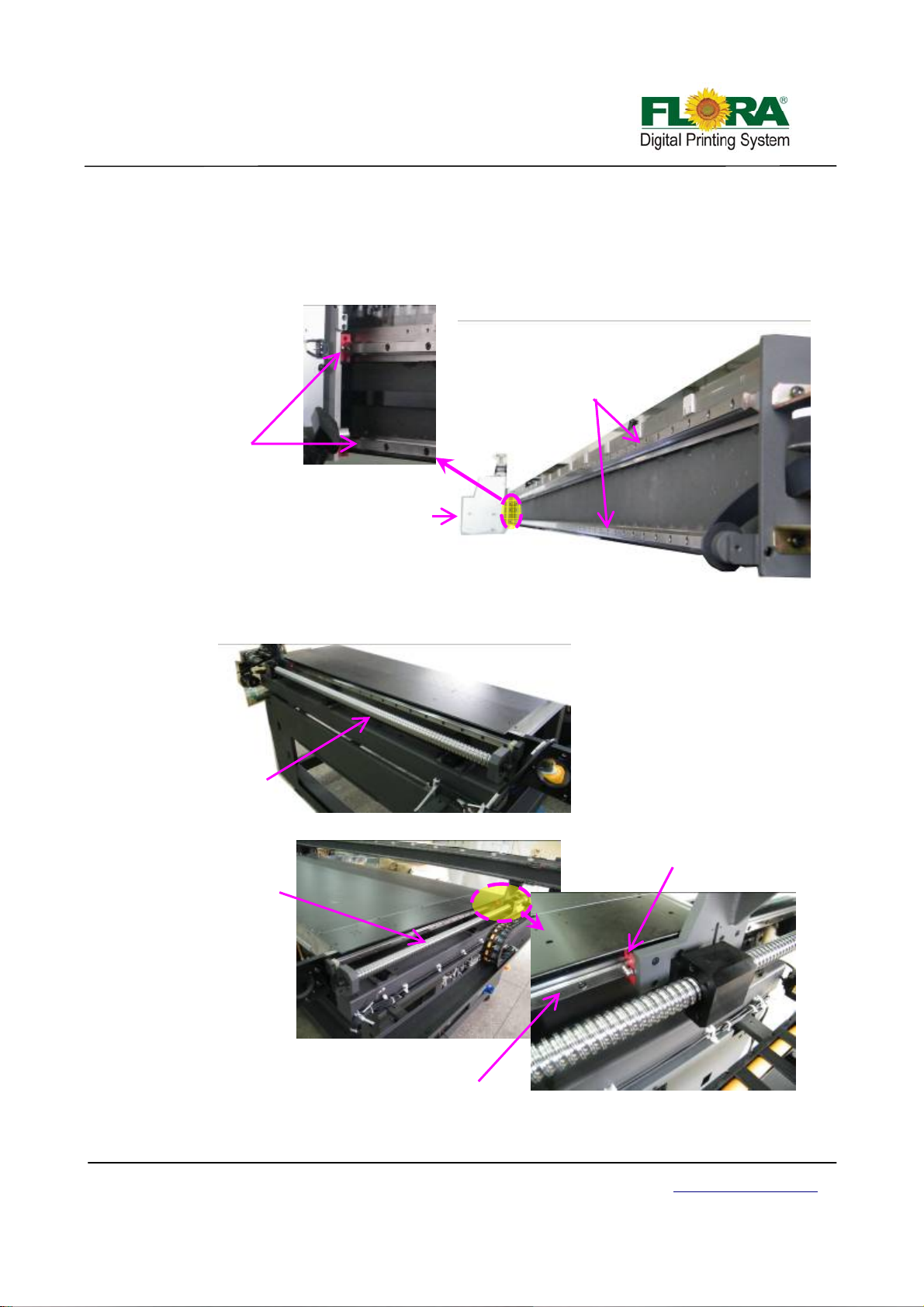
3.3 Rail guide and Beam Assembly
Rail guide supports pathway for carriage and Beam moving, and the beam serves as frame for
rail guide mounting.
3.3.1 X-axis Rail guide and Beam
Bearing slider
Enlarge View
Carriage Assembly
Dual Liner Lead Rail
Beam Assembl
3.3.2 Y-axis Rail guide
Left lead screw
Left View
Liner bearing
Right lead screw
Right
iew
Liner lead rail
Victor Xu Page 16 12 Jan. 2011
Copyright 2011 © Shenzhen Runtianzhi Image Technology, Co., Ltd.
http://www.floradigital.com
Enlarge View
Page 17
butto
A
3.4 Control Panel
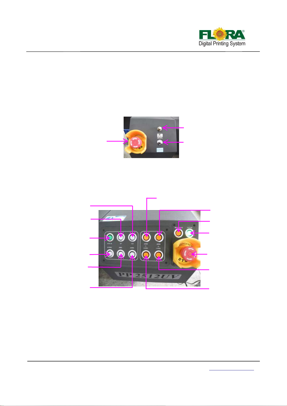
3.4.1 Maintenance Control Panel
The maintenance control panel is placed at left should er.
The ink prime button is use to purge ink out of the print head nozzles, which will help purge
the print head.
The negative pressure regulator can be used to adjust negative pressure.
The E-stop button will shut off main power supply to this machine when emergency situation,
which will protect the print head from damaged.
3.4.2 Movement and UV lamp Control Panel
E-stop button
Negative Pressure
Regulator
Priming Button
The operation panel serves as the interface between the machine and the operator. The
machine is set online or off line through the on line/off line button. Once the machine is offline from
the computer, the movement of the machine can be operated from the operation panel. The UV
lamp can be turned on or off from the operational panel.
Right
Left button
n
UV1 low power button
UV2 low power
button
Locator button
On/off line button
ir blower button
Maintenance button
E-stop button
Forward button
UV2 high power
button
Backward button
Enlarged View of Control Panel
UV1 high power
button
On line/Off line Button: This button will set the printer to be connected or disconnected
with the computer. Push to set on line and push again to set off line. If the machine is off line
the button lamp is turned on, or it will be turned off.
Maintenance Button: The carriage will start automatic print head nozzle clean up
procedure. It will purge ink to the print head to refresh the nozzles and perform suction
cleaning.
Left Button: This button if the printer is set offline will move the carriage to the left.
Right Button: This button if the printer is set offline will move the carriage to the right.
Victor Xu Page 17 12 Jan. 2011
Copyright 2011 © Shenzhen Runtianzhi Image Technology, Co., Ltd.
http://www.floradigital.com
Page 18
Forward Button: Pressing this button will make the beam towards the operator.
Backward Button: Pressing this button will make the beam away from the operator.
UV Buttons: The UV Buttons will turn on/off the UV lamps. UV1 Buttons controls the left UV
lamp while the UV2 controls the right UV lamp.
Media guide Button: This button will pop up the pin to help locate the media.
Suction Button: This button will change the air flow direction in the vacuum chamber, which
will help to push the media away from the flat bed.
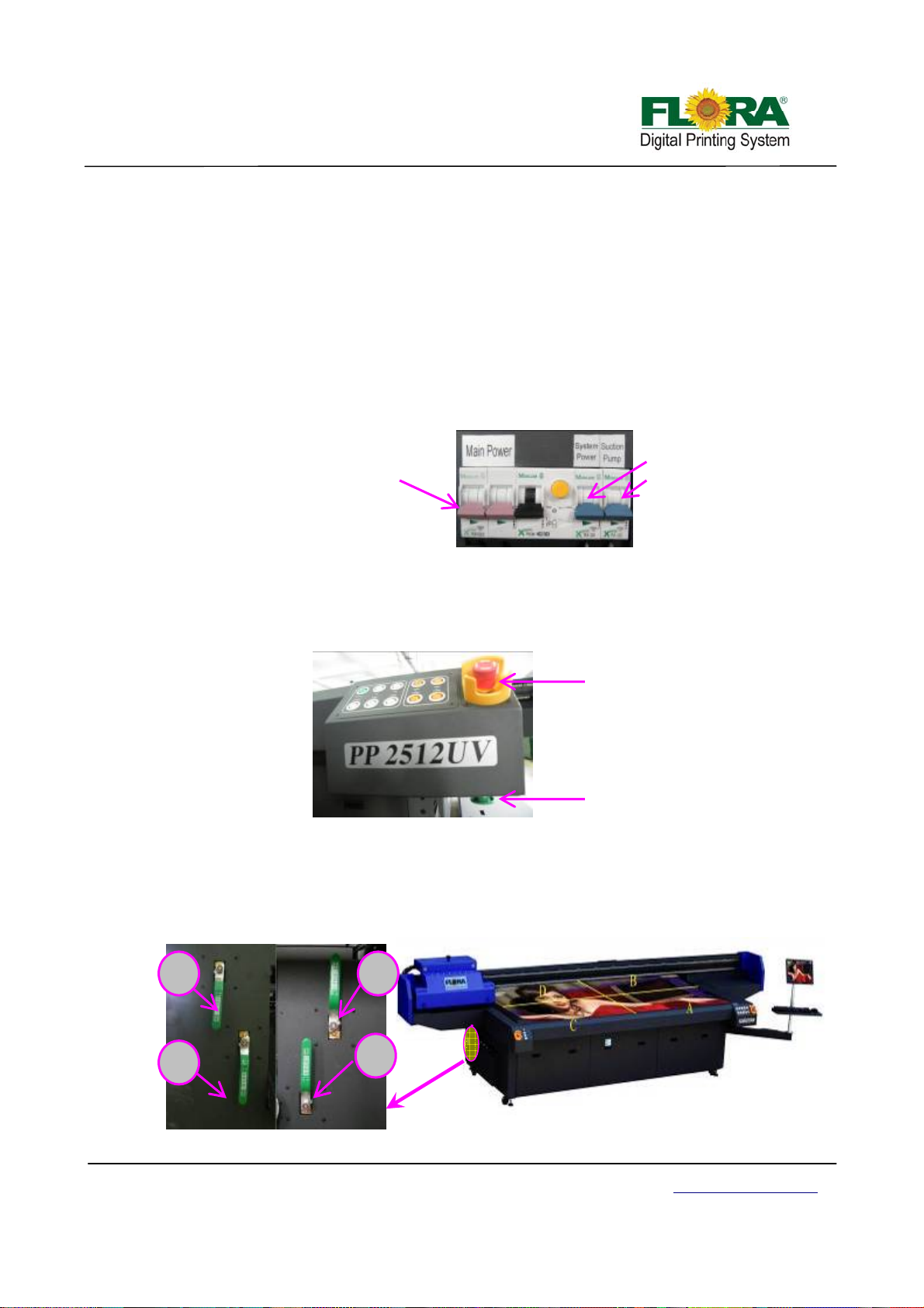
3.4.3 Main Circuit Breaker
Main power switch controls the AC power input.
System power switch controls the DC power for PCB boards etc.
Suction pump switch controls the vacuum on or off.
Main power double
throw-Switch
System power single
throw-Switch
Suction Pump single
throw-Switch
3.4.4 Start and E-Stop Button
The start button is placed below the control panel. This switch will not work if the emergency
stop button is not released. To release the E-stop button simply turn is according to arrow head
direction. Pressing the start button will restore electrical power to the printer.
The emergency stop button is placed at the front corners edges of the machine. Once it is
activated/ pressed, electrical power for the printer controls is cut-off.
E-Stop Button
Start Button
3.4.5 Vacuum Chamber Control Valves
The vacuum flat bed is divided into four (4) vacuum chambers. Vacuum area could be
adjusted according to the media size. The numbers on the flat bed signifies the valve number, so if
you want to print on 1.2 m x 0.6 m size media you can close valves B, C and D leaving vacuum
chamber A open.
D
C
B
A
Flat Bed View
Left valve
Victor Xu Page 18 12 Jan. 2011
Copyright 2011 © Shenzhen Runtianzhi Image Technology, Co., Ltd.
Right valve
http://www.floradigital.com
Page 19
(
)
(
)
3.5 Electrical fixation Shelf
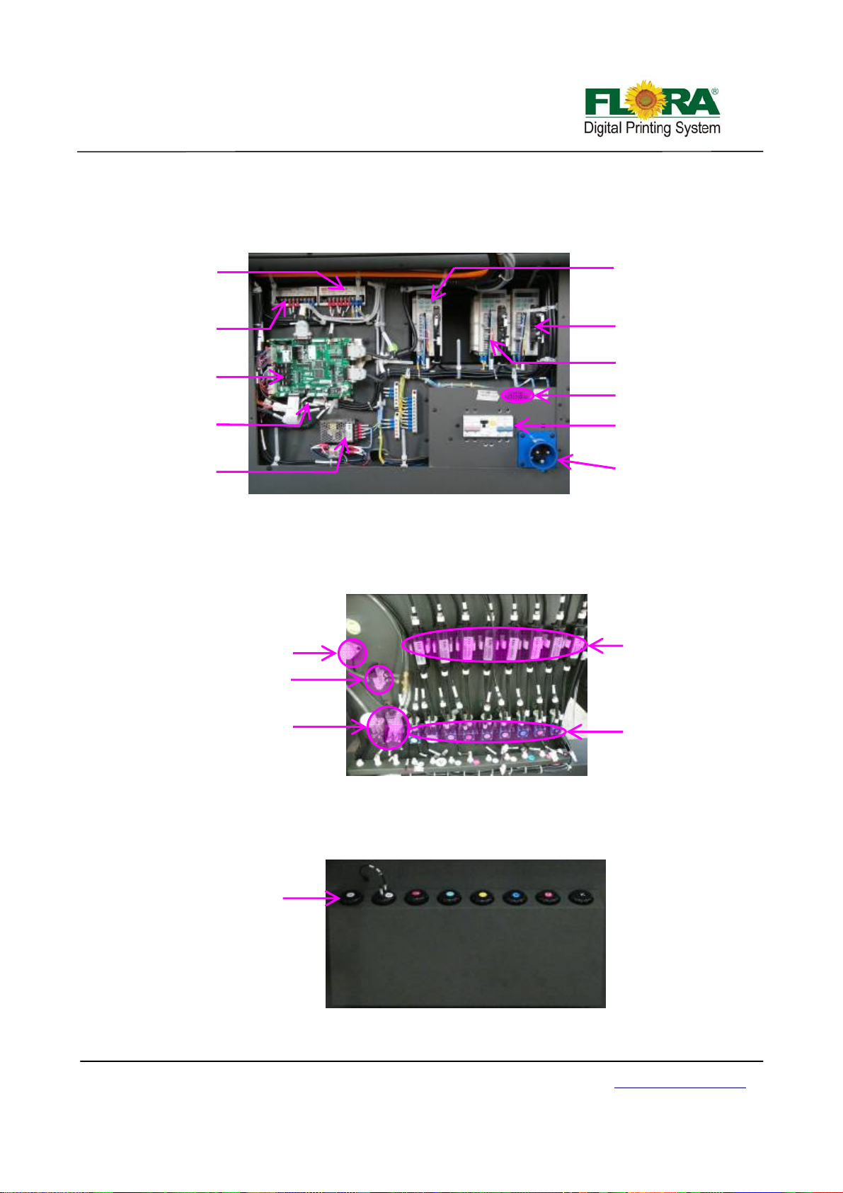
The electrical control panel contai ns the servo motor drivers for the Beam Movement servo
motors, Carriage servo motor and Media Feeding and Take-Up System servo motor, DC Power supplies,
Servo card, USB_IF control board and the Main Circuit breaker.
Power Supply 1
24 Vdc
Power Supply 2
(15 Vdc)
Servo Card
USB_IF Board
Power Supply 3
15 Vdc
Electrical Control Chamber
Servo Driver for
Carriage
Servo Driver for Beam
Right Servo motor
Servo Driver for Beam Left
Servo motor
NP Extend Power Inlet
Main Circuit
Breaker
AC Power Inlet
3.6 Ink Supply Control Compartment
It is located on the side of the ink bottles compartment. The buzzer, negative pressure air pump
and the corresponding ink supply pumps are mounted on the ink supply control compartment.
Solenoid Valve
Buzzer
Air pump
3.7 Ink Bottle Compartment
It serves as a compartment for ink and waste bottles and is located at the back of the machine.
Ink supply control compartment
Ink bottle
compartment
Ink Bottle Compartment
Ink filter
Ink pump
Victor Xu Page 19 12 Jan. 2011
Copyright 2011 © Shenzhen Runtianzhi Image Technology, Co., Ltd.
http://www.floradigital.com
Page 20
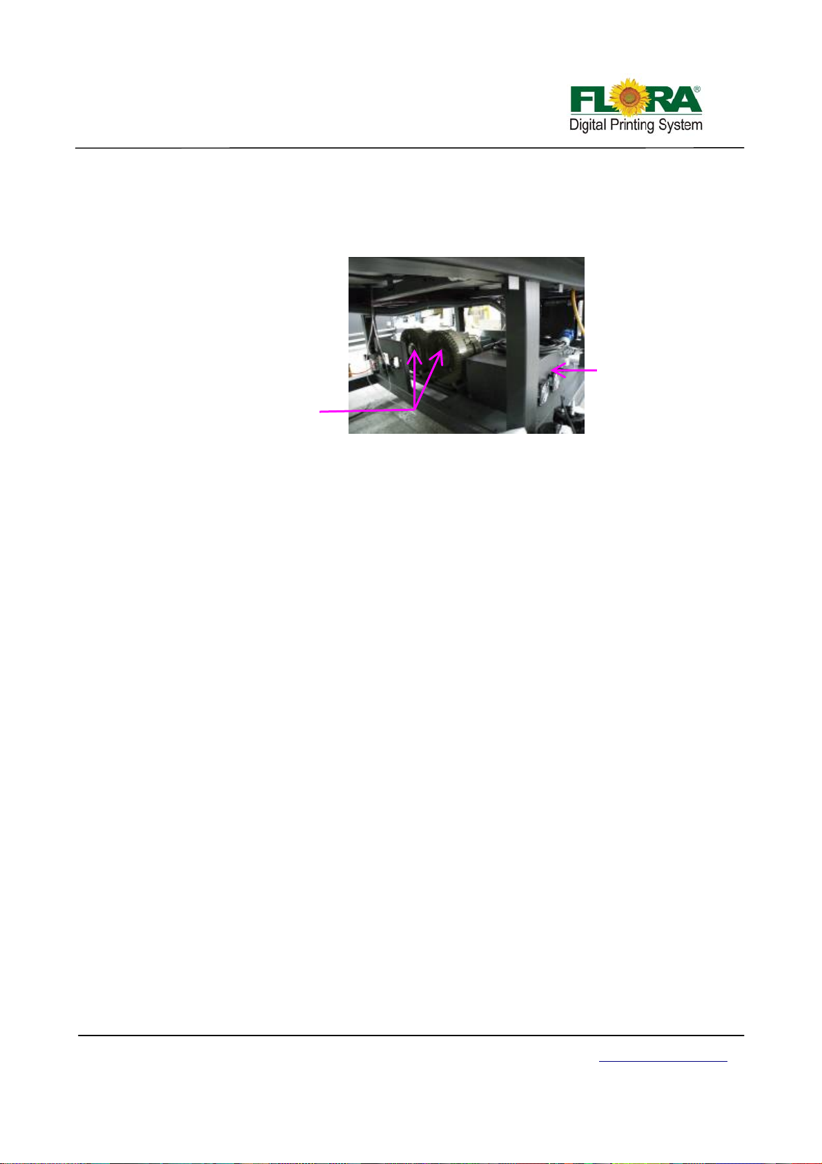
3.8 UV Power Supply & Vacuum Pump
The UV power supply provides power to UV lamps and the intensity of light can be adjusted to
Low or High. While the Media suction pumps provide suction on the flat bed to hold the media in place
while printing is on progress. Vacuum manifold enhance the suction strength.
Vacuum pump
UV power supply
2.5 Starting the printer
1. Make sure there is no media or materials on top of conveyor belt specifically along the path
of carriage during printing.
2. Plug the machine power cord to the electrical power sou rce outlet.
3. Check and reset all emergency stop buttons.
4. Turn on the circuit breaker, leaving the breaker for the vacuum pump turned off.
5. Turn on the computer and plug the Dongle if necessary.
6. Press the machine start button.
7. Open the maintenance compartment door to show the print head carriage status.
8. Open the negative pressure shut-off valves both at the front and back.
9. Activate the ink prime toggle switch.
10. Press the on line/off line button on the control panel to disconnect the machine from PC.
11. Press maintenance button, this will automatically start the suction cleaning of the print heads.
12. Test the movement of the printer by moving the carriage using the operation panel. Left, right,
forward and backward, to check mechanical functionality.
13. When everything is verified to be functional, set the printer to on line by pressing the on
line/off line button.
14. Open the Photoprint software and machine is ready for operation.
Victor Xu Page 20 12 Jan. 2011
Copyright 2011 © Shenzhen Runtianzhi Image Technology, Co., Ltd.
http://www.floradigital.com
Page 21
Chapter 4 - Working System of Flora PP 2512UV
4.1 Brief Introduction
The Flora PP 2512UV large format printer is using raster image technology to process photos
stored in computer. It is one of the most innovative products, which combines photo digital technology
with high precision engine driver. It produces super wide printouts for busine ss use.
and maintenance procedures. Though simple, it is composed of several precise systems. In this chapter,
we will introduce the system components and operator guide.
4.2 The Konica Minolta Print head Assembly
high-speed and compact inkjet print head lineup suitable for both wide format and industrial applications.
move by applying an electric field across it. Ink channels composed of piezo walls can eject small drops
of ink in accordance with the electrical signals applied to the electrodes on the walls.
generate a pressure wave inside the channel. This mechanical ejection principle allows a wide range of
inks including oil and solvents, which is a great advantage when compared with the thermal ejection
inkjet head.
It is a high technology equipment with a user friendly operating system with simple operational
In a high quality and high performance configuration, Konica Print head offers a high-resolution,
Konica Minolta print heads are based on piezo-electric materials (PZT), in which can be made to
The KM512 Print Head is driven by “shear mode”, in which the walls bend inward and outward to
This section introduces the KM512 Print Head technologies.
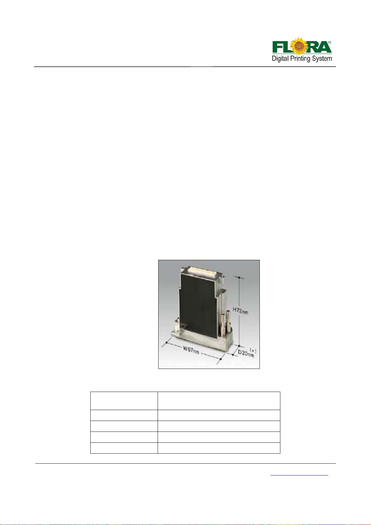
Konica Minolta Print head Dimensions
Main Features:
Technology
Piezo Drop On Demand (Shared Wall 3
Cycle)
Number of Nozzles 512 Nozzles (256 nozzles x 2 rows)
Resolution 360 dpi
Nozzle Spacing 70.5um pitch (141 um pitch×2 rows)
Maximum Frequency 12.8 kHz
Victor Xu Page 21 12 Jan. 2011
Copyright 2011 © Shenzhen Runtianzhi Image Technology, Co., Ltd.
http://www.floradigital.com
Page 22
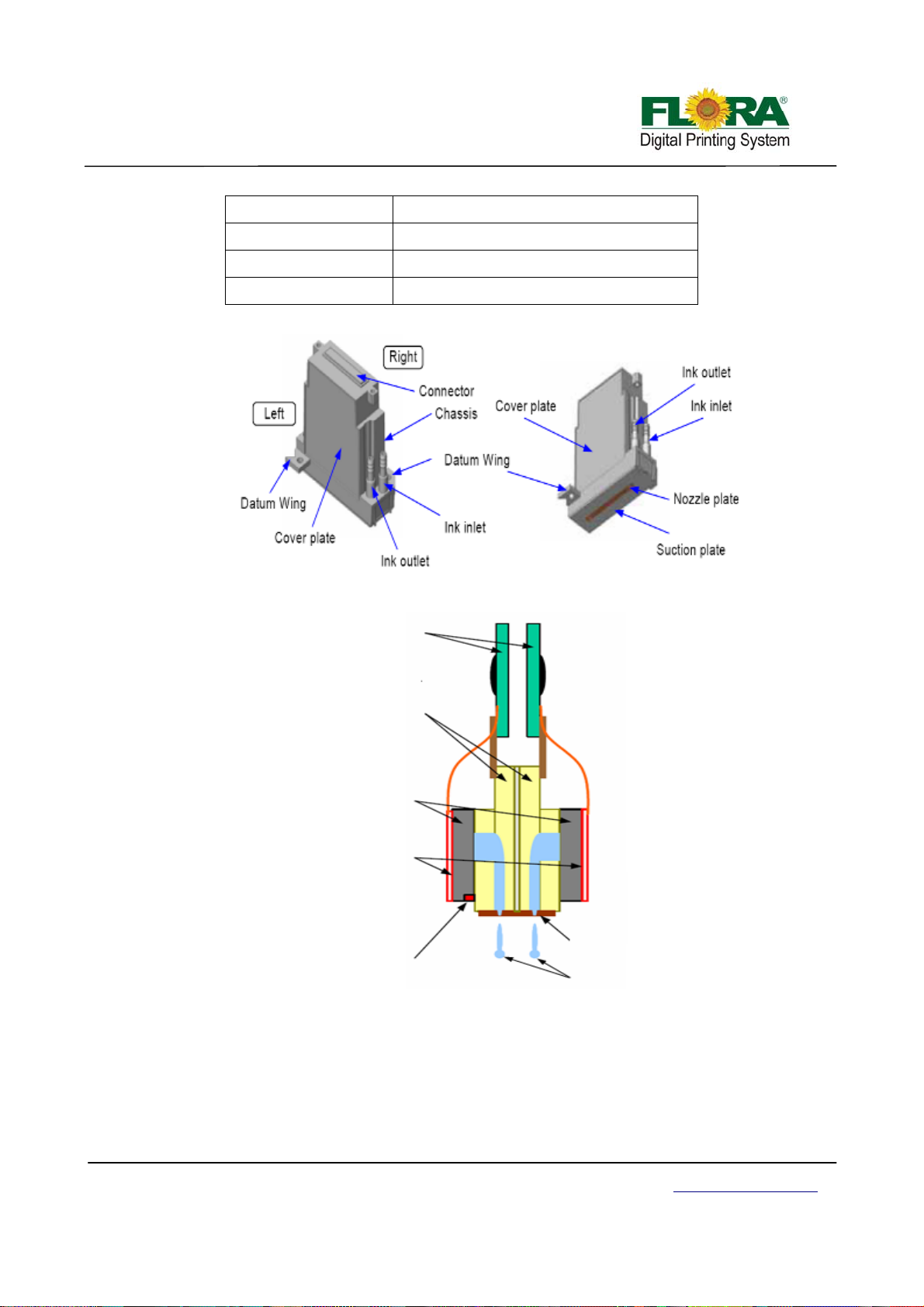
Drop Volum e/Size 14 pL
Drop Speed 6 ± 0.5 m/s
Printing Width 36.03 mm
Heater Temperature Under 55 ºC
Drive Board
Head Chip
Manifold
Left Side
Right Side
Heater
Thermistor
Parts of the Konica Minolta
Nozzle Plate
Ink Jet
4.3 PCB boards
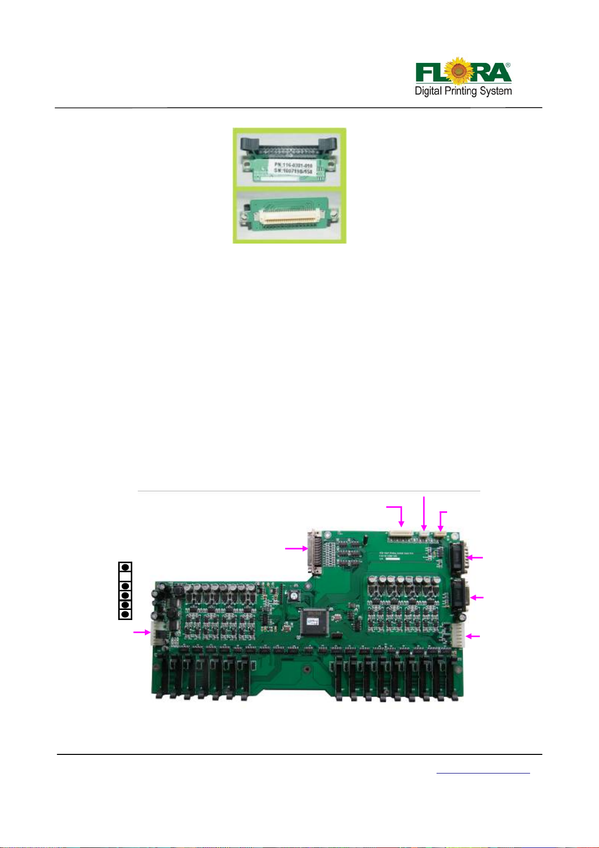
4.3.1 Print Head Connector Board
This board is used a s interface board for Print head and the Print head Control Board thru a
30-pin flexible data cable. It is fixed on the print head by two fixation screws,
Victor Xu Page 22 12 Jan. 2011
Copyright 2011 © Shenzhen Runtianzhi Image Technology, Co., Ltd.
http://www.floradigital.com
Page 23
No use
15Vdc
15Vdc
24Vdc
J1 to Power
Source (15/24
Vdc)
Print Head Connector Board
4.3.2 Print head Control Board
The image data is fetched by the Print Head Control Board from the USB_IF buffer through
the Image Data Cable (UCBJ10PHBJP1) and 100-pin JP1 AMP connector. The image is then
processed by the image data processor and dispatch to the print heads. The printheads fires the
ink depending on the binary status read by the Raster Reader which is sent to the print head
control board.
Likewise, the print head heating control is also integrated into the Print Head Control Board.
Thus, the print head temperature can be accessed from the Floraprint driver graphical user
interface or GUI.
The carriage displacement pulse signal is sent from the encoder reader to the print head
control board through PHBJ9ENR1 into J9 D-sub connector.
The secondary ink tank level sensor signal from the secondary ink tanks pass through cable
J2 and into the J2 connector of the print head control board. If the secondary ink tanks are full,
corresponding LED indicators will turn on near the J4 connector. The binary status for the
secondary ink tank level is then sent to the Servo Driver Board through cable SCBJ7PHBJ7. It is
then processed on the Servo Control Board to activate the ink pump motors.
The shutters of the UV lamps were also controlled from the Print Head Control Board.
J3 No Use
J4 To Negative
Pressure Sensor
J7 to Servo
Control Board
J6 to Raster
strip reader
J5 UV Lamp
Shutter Control
GND
GND
J2 to ink level sensors
JP1 to USB IF
Victor Xu Page 23 12 Jan. 2011
Copyright 2011 © Shenzhen Runtianzhi Image Technology, Co., Ltd.
http://www.floradigital.com
Page 24
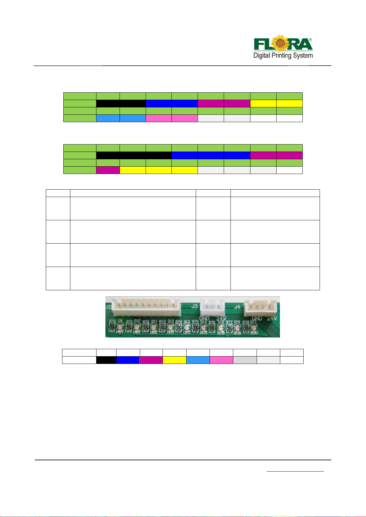
Interfaces for print heads:
Carriage platform with two rows print heads:
PORT JB1 JB2 JB3 JB4 JB5 JB6 JB7 JB8
COLOR
PORT
COLOR
**Double white just replaceV1, V2 with W3, W4
Carriage platform with three rows print heads:
PORT JB1 JB2 JB3 JB4 JB5 JB6 JB7 JB8
COLOR
PORT
COLOR
K1 K2 C1 C2 M1 M2 Y1 Y2
JB9 JB10 JB11 JB12 JB13 JB14 JB15 JB16
Lc1 Lc2 Lm1 Lm2 W1 W2 V1 V2
K1 K2 K3 C1 C2 C3 M1 M2
JB9 JB10 JB11 JB12 JB13 JB14 JB15 JB16
M3 Y1 Y2 Y3 W1 W2 W3
Function of LEDs
LED Function description LED Function description
D1
D2
D3
D4
Power indicator for 24V
normal:on
abnormal:off
Power indicator for heat of print head 15V
normal:on
abnormal:off
Power indicator for 5V
normal:on
abnormal:off
Raster indicator
Carriage moving:light
Carriage keeping still:off
D5
D6
D9~D17
—— ————
Work indicator
Board work normally:shine
abnormal:off
Temperature indicator
heating:on
no heating:off
Level indicator
Tank full:on
not full:off
Ink level indicators for every color:
LED D9 D10 D11 D12 D13 D14 D15 D16 D17
COLOR K C M Y Lc Lm W V NP
*K: Black, C: Cyan, M: Magenta, Y: Yellow, Lm: Light magenta, Lc: Light cyan, W: White, V: Varnish,
NP: Negative pressure
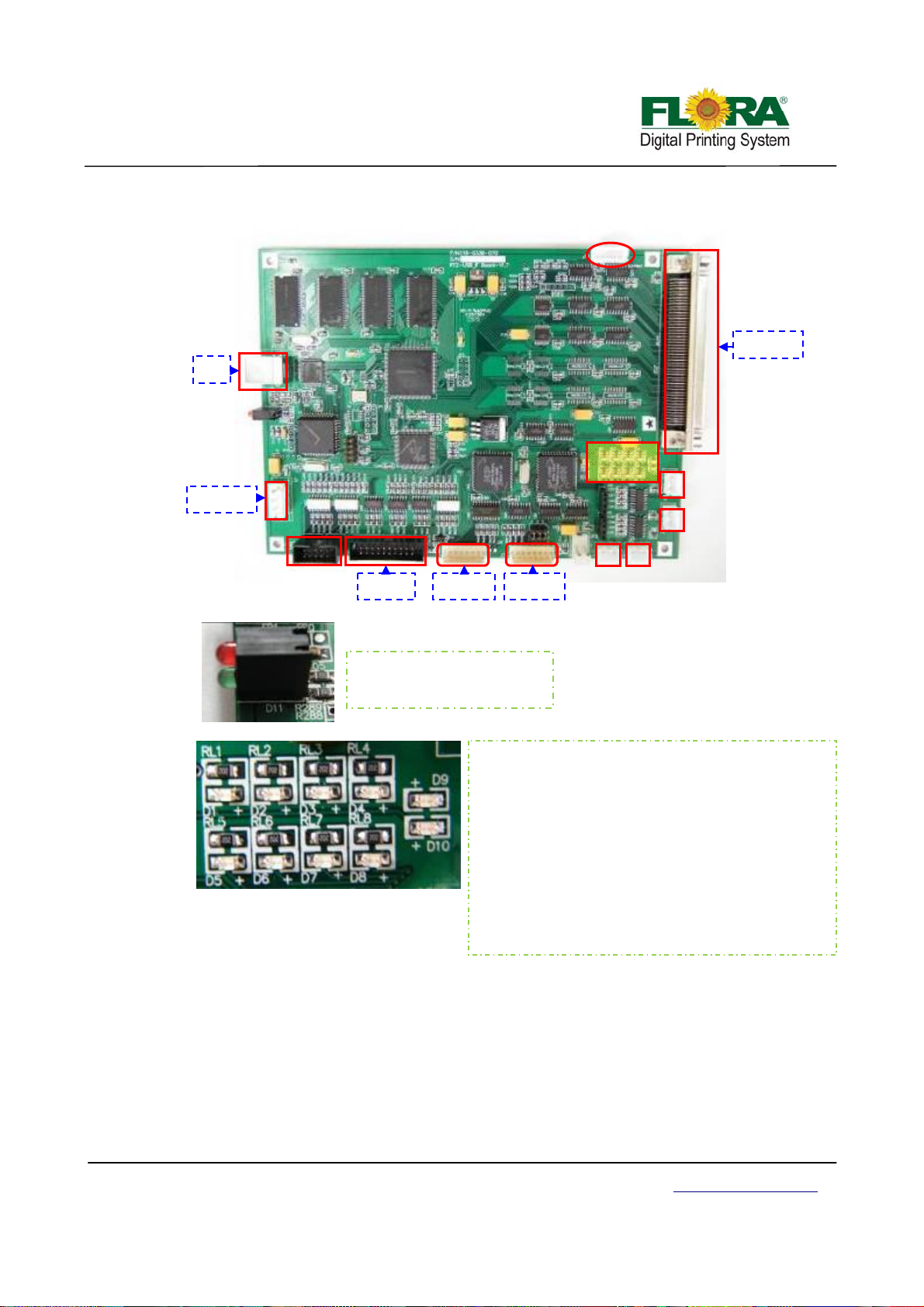
4.3.3 USB Interface Board
The USB board is the main interface of the machine to PC. The image data and control
information are transmitted from the PC USB port to the USB port of this board. The
communication and image data transfer are conveyed through the 100-pin data cable.
For this particular printer model, the USB board is also used to communicate with and
control the servo driver control board.
There is a separate control circuitry designed to control the x-axis and y-axis movement. It
conveys a signal for the servomotor step and direction; and hence, the servo driver can be able
Victor Xu Page 24 12 Jan. 2011
Copyright 2011 © Shenzhen Runtianzhi Image Technology, Co., Ltd.
http://www.floradigital.com
Page 25
Y
to drive the servo system mechanism.
J11
PC
P1
J10
PHB JP1
5V input
J1
J9
J2
J5
SCB J5
X-axis
-axis
Green Led: power indicator
Red Led: connection indicator
4.3.4 Servo Card
Communication indicator:
D1: NULL
D2: NULL
D3: NULL
D4: NULL
D5: Print head board indicator Communication: on
D6: Y-axis indicator Y motor moving: on
D7: Servo Card indicator Communication: on
D8: X-axis indicator Y motor moving: on
D9: RX indicator Receiving data: on
D10: TX indicator Transmitting data: on
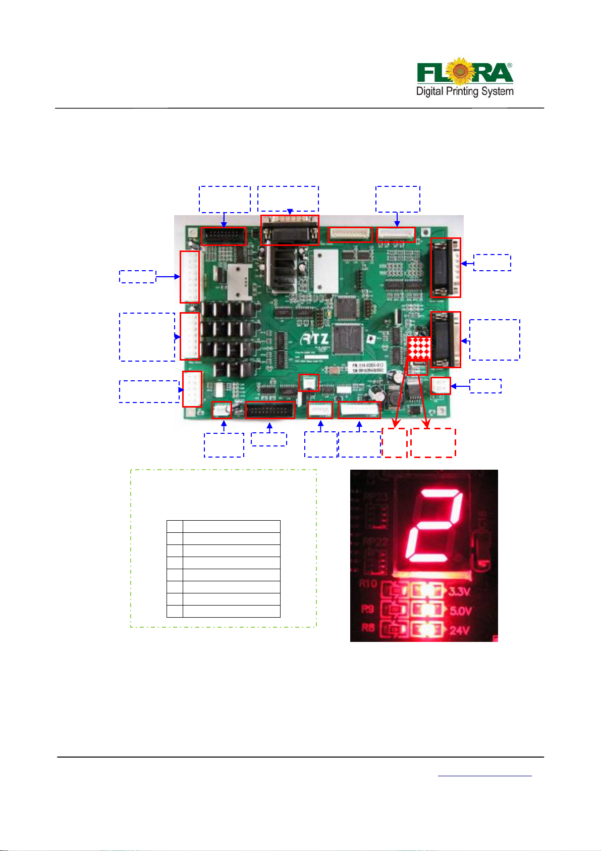
The Servo Card or sometimes Servo Driver Board serves as the movement control board
and ink control board packed into one circuit board.
Power to the corresponding ink pumps are sent by this PCB as well as the control signals
from the secondary ink tank level sensors are being received and processed. This binary
information about the status are being processed accordingly in order to provide the power to turn
on the ink pumps to fill in the secondary ink tanks.
The control for the automatic carriage height adjustment is also handled by this PCB as well
as the UV status and the carriage limit sensors. The controls for the ink prime and printhead
Victor Xu Page 25 12 Jan. 2011
Copyright 2011 © Shenzhen Runtianzhi Image Technology, Co., Ltd.
http://www.floradigital.com
Page 26
J9J
p
&mag
cleaning are also handled by this board. The inputs from the status of the switch on the operational
panel are being received and processed by this board. The connectors J15, JP1, JP2 and JP5 are
not use.
Level sensor
of ink bottle
Ink pum
J14
Clean motor
netic
J3
Control
panel
1
J7
PHB J7
Air pump1#
buzzer
w-w pump
air pump2#
J13
J4
Z-axis motor
Raster
reader Ltd.
Priming button
J11
DC24V
Protection
switch
USB J5
Limited
switch
UV power
box
Nixie
Tube
Power
indicator
Power indicator:
Power is ok, on; or, off.
Nixie Tube:
Show the error number .
0 No problem
1 Lack of ink
2 Negative problem
3 Movement problem
4 UV lamp problem
5 ------6 ------7 No ink in the bottle
Error indicator----Nixie Tube
1) If the digital LED shows 0, it means everything is ok, with no problem.
2) Number 1 means that there is no ink in the secondary tank:
¾ If there is a sound of buzzer, choose “flood” in the GUI of flora driver;
¾ Else check the indicator LED on the Printing Control Board, if the negative pressure
tank level indicator LED is on, you need to go to 3) and solve the over flow problem first. After that :
First, check the ink bottle: make sure the ink bottle is not empty, if there is no
Victor Xu Page 26 12 Jan. 2011
Copyright 2011 © Shenzhen Runtianzhi Image Technology, Co., Ltd.
http://www.floradigital.com
Page 27

ink ,then load ink;
Second, check the ink pump: make sure the pump is not damaged, if it is
bad, change it;
Third, check the sensor: make sure the sensor can detect the level exactly,
otherwise change it;
If everything can’t work still, change Servo Card.
3) Number 2 means some ink over flowed, which also means there is ink in the negative
pressure tank:
¾ Check the ink indicator LED is light or not, it means there is ink in the negative
pressure tank when it’s on. Then you need to suck ink out from the tank by injector first before you
start the machine
4) Number 3 means the movement system has problem
¾ First, check the servo driver report the error or not: if there is a error, shut down the
power of the machine and restart it.
¾ Secondly, check the limited switch: the left & right limited switches are used for
protection. If the switch is pressed, it will stop the motor from working. So you must make sure that
switch is ok and it hasn’t been pressed by carriage or any other thing.
¾ Third, check the motor can work normally or not. If necessary, change it.
¾ Forth, if it still can work, change the USB Board.
5) Number 4 means the UV lamp is not opened.
6) Number 7 means there is no ink in the ink bottle/barrel
Number 5&6 is no use.
4.4 Moving system
4.4.1 X-axis (Carriage moving system)
4.4.1.1 Servo Driver Pack
The Carriage and Beam assembly are driven by Servomotors and are controlled by
their respective Servo Driver. This servo motors are basically two-phase, reversible, induction
motors modified for servo operation and used in applications requiring rapid and accurate
response characteristics. To achieve these characteristics, this ac servo motors have small
diameter, high resistance rotors. The ac servo motor's small diameter provides low inertia for
fast starts, stops, and reversals. High resistance provides nearly linear speed-torque
characteristics for accurate servo motor control.
Servo Driver 1 (SD1) controls the right servomotor for beam assembly, Servo driver 2
(SD2) controls the left servomotor for beam assembly, Servo Driver 3 (SD3) is optional,
controls the servomotor for Media handling system and Servo Driver 4 (SD4) controls the
servomotor for carriage.
X-axis SD
AC power
supply
To USB J3
To encoder of SM4
Y-axis SD2
Y-axis SD1
To USB J4
To encoder of SM1
To encoder of SM2
Victor Xu Page 27 12 Jan. 2011
Copyright 2011 © Shenzhen Runtianzhi Image Technology, Co., Ltd.
http://www.floradigital.com
Page 28
g
4.4.1.2 Servo motor
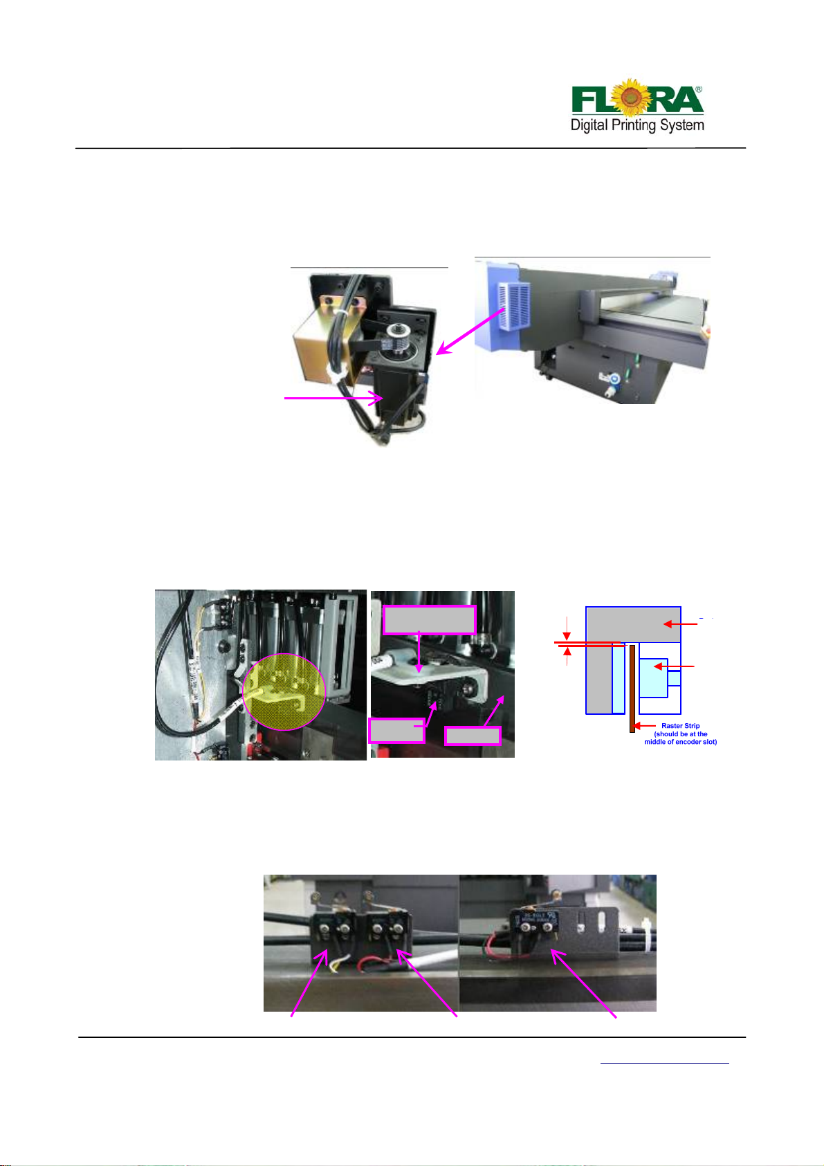
Servomotors (SM) are controlled by their respective Servo Drivers (SD). They are
responsible in driving carriage X-axis, Y-axis and Z-axis movements.
SD4 controls the SM4 which is responsible in driving the carriage X-axis movement. It
is installed at the right end of the beam.
Servo motor
Machine Back View
4.4.1.3 Raster reader and strip
The Raster Strip
to form a vertical line, the pitching and number of dots depends on the DPI specification of the
strip. The Raster Encoder
length and then generates pulses that will be sent to the Print head to fire the ink droplets.
The Raster Encoder is installed at the back right side of the carriage while the Raster
Strip is installed on the beam through out its length.
4.4.1.4 Limited switch
One is at the right end while the other two are at carriage home position. These switches will
stop the carriage to move further in case it over shoot due to servomotor malfunctions.
Raster Encoder
There are three limited switches installed for carriage assembly X-axis movement.
(Raster Ruler) is a transparent plastic stri p marked with d ots arranged
(Raster Reader) is responsible for reading the lines across the strip
Raster Encoder
Mountin
Raster
Bracket
Enlarged View
Raster Strip
1.0–1.5 mm
Raster Encoder Setup
Raster
Encoder
Optical
Sensor
Left End Limited Switch
Victor Xu Page 28 12 Jan. 2011
Copyright 2011 © Shenzhen Runtianzhi Image Technology, Co., Ltd.
Home position Limited Switch
Right End Limited Switch
http://www.floradigital.com
Page 29

4.4.1.5 Anti-crash Sensor
The safety anti-crash sensor designed on both sides of carriage can detect the media
circumstance beforehand and protect the print heads from a crush hazard. While the anticrash sensor detects that the edge of media is cocked, the machine will initiate an emergency
stop to prevent print heads from damage.
Carriage Assembly
4.4.2 Y-axis (Beam moving system)
Anti-crash Sensor
4.4.2.1 Servo Driver Pack
Please refer to 4.4.1.1 for digital.
4.4.2.2 Servo motor
SD1 controls the SM1 which is responsible in driving the left worm gear while SD2
controls the SM2 which responsible for the right worm gear. Both servomotors should be
synchronized so the beam assembly will move parallel to X-axis of the carriage.
Pulley Pulley
4.4.2.3 Limited switch and optical switch
There are in total 4 limited switches and 2 optical switches. These limit switches are
installed near the end of each worm gear. The 2 optical switches serve as home position for
carriage beam, while the limit switches serve as end protection switch. These switches will
stop the carriage beam to move further in case the carriage over shoot due to servomotor
malfunctions.
Left side SM1
Right side SM2
Victor Xu Page 29 12 Jan. 2011
Copyright 2011 © Shenzhen Runtianzhi Image Technology, Co., Ltd.
http://www.floradigital.com
Page 30
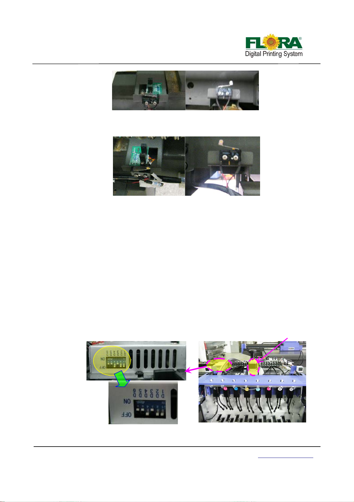
Left home position switch & back limited switch
Right home position switch&back limited switch
4.4.3 Z-axis (Auto height adjusting system)
In order for the printer to print seamlessly on different kinds of media, the carriage height
should adjust automatically to whatever media thickness it should print upon. For this specific
printer model it is equipped with a carriage that could automatically adjust its height depending on
the media thickness to be printed upon. The user can choose whether to print using the default
carriage gap between media of 2.0 mm or opt to increase the gap up to 5mm.
The assembly uses a solenoid activated mechanical touch sensor to sense the media height.
This mechanical sensor protrudes downward from the carriage assembly during media height test.
The system also uses a raster strip and encoder to determine the accurate height adjustment from
default height settings.
4.4.3.1 Stepper driver & motor
Carriage height adjuster stepper motor is responsible in driving the carriage up/down
movement. A height adjuster knob is provided in case the carriage needs to be move up/down
manually for some reason.
Stepper motor
Driver Pack DIP-switch Setting
Top Front View of the Carriage
Victor Xu Page 30 12 Jan. 2011
Copyright 2011 © Shenzhen Runtianzhi Image Technology, Co., Ltd.
http://www.floradigital.com
Page 31
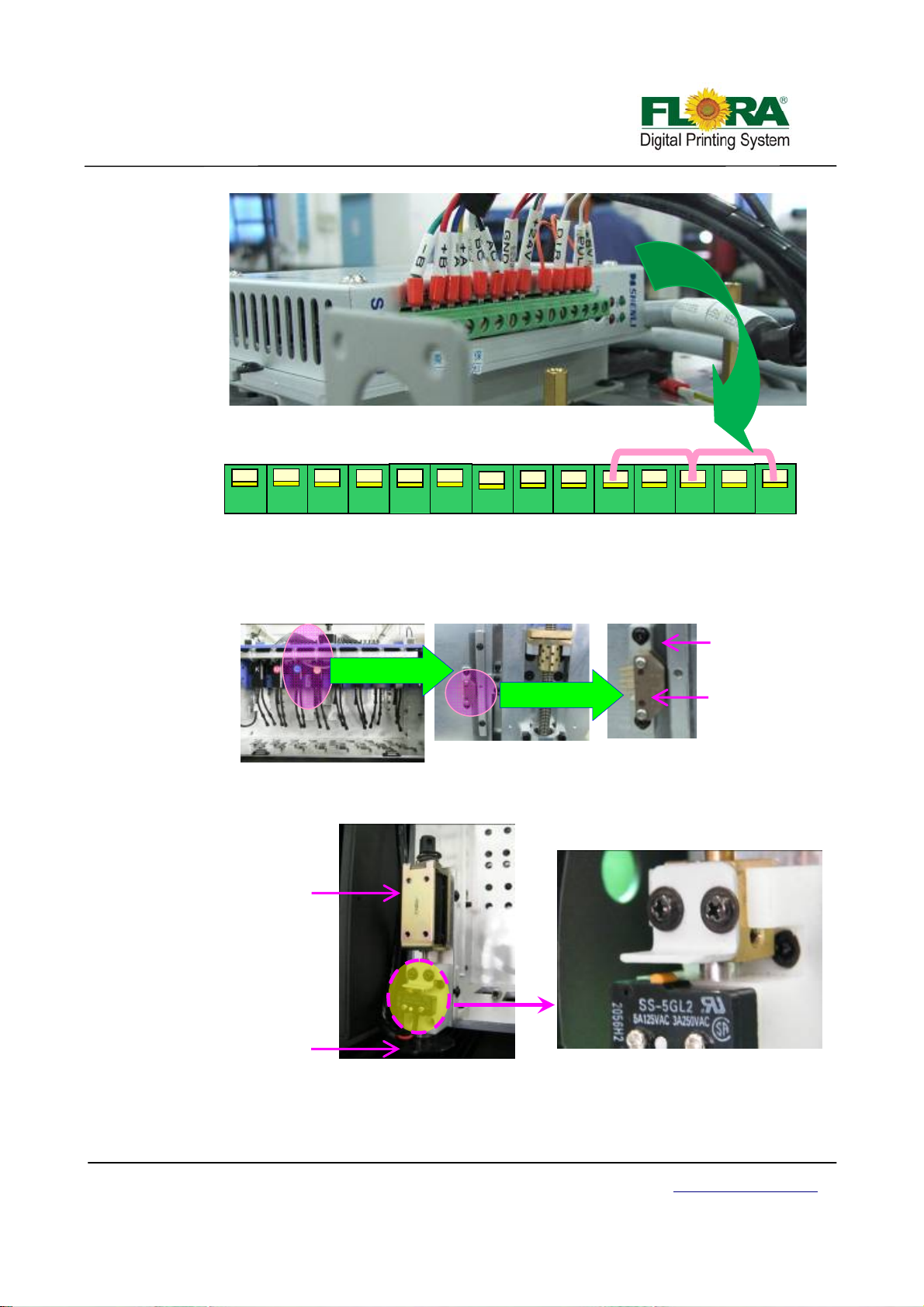
encode
aster Strip
g
A
Photographic Side View of Height Adjustment Module
BC
4.4.3.2 Raster reader and strip
B-
Cable connections Illustration for Carriage Height Adjustment Module
A-
B+
+
C +
+24Vdc
DIR
The Raster Encoder and Raster Strip are installed inside the back plate of carriage
besides the worm gear for moving the carriage up and down.
200DPI
R
4.4.3.3 Detecting sensor
Front of Carria
Detecting sensor is supplied to detect the distance from the print head to media.
e
Removed Cover
200DPI Raster
r
Electromagnet
Plastic Disc
4.4.3.4 Limited switch
Detecting Sensor
Enlarge View
These limit switches are installed at the right side upper portion of the carriage. The
Victor Xu Page 31 12 Jan. 2011
Copyright 2011 © Shenzhen Runtianzhi Image Technology, Co., Ltd.
http://www.floradigital.com
Page 32
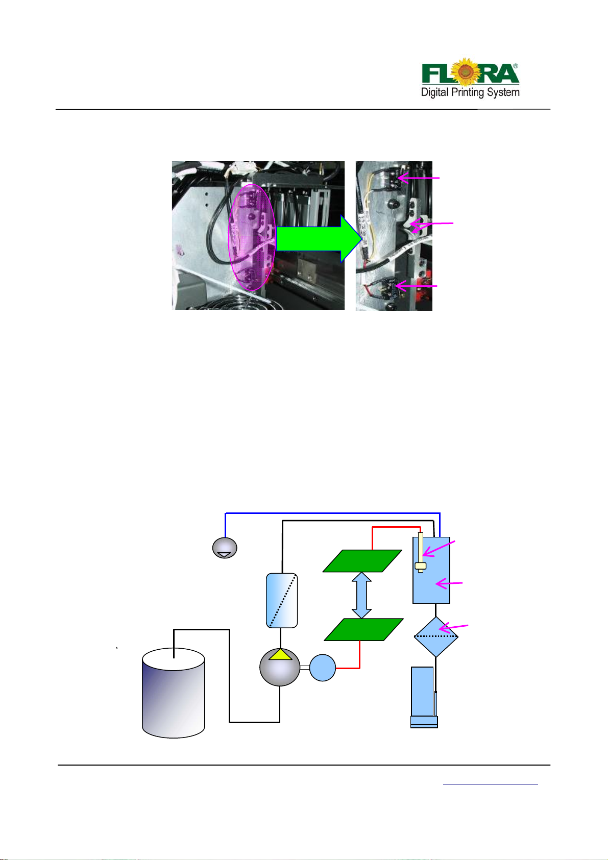
lower limit switch and the upper limit switch control the carriage highest and lowest allowable
height the carriage can move respectively.
4.5 Ink supply& negative pressure system
4.5.1 Ink supply system
Right Side of the Carriage
Carriage minimum
height limit switch
Switch
actuators
Carriage maximum
height limit switch
Enlarged View
The ink Bottle/Barrel serves as the main reservoir for ink supply, should be refilled in a timely
manner so continuous supply of ink will not be interrupted during printing. The level of ink inside
the bottle/barrel can be monitored visually or using the buzzer system. Refilling is done manually.
The ink pumps suck and discharge the ink into the secondary ink tank. A five-micron filter is
being provided to prevent the secondary tank from being contaminated by unwanted particles,
which are inherent in the ink. Ink level sensor inside the secondary ink tank sends an open or close
contact signal to the Print head control board and Ink control board to control the operation of the
pumps. An optional micro filter is added to enhance the filtering of ink before it flows into the print
heads.
Every time the print heads eject/fire ink droplets, the ink flows and fills the space left by
droplets. A negative pressure system is responsible for holding the ink from flowing out of the print
head nozzles.
Negative
Pressure
Pump
Ink Filter
(Barrel Type)
Ink Level
Sensor
Printhead
Control Board
Secondary
Ink Tank
Servo Driver
Control Board
Last Chance
Filter
Ink Barrel
Ink
Pump
M
Ink Control System
Victor Xu Page 32 12 Jan. 2011
Copyright 2011 © Shenzhen Runtianzhi Image Technology, Co., Ltd.
http://www.floradigital.com
Page 33
4.5.2 White ink circulation system
White ink is different from other color ink, because it is easy to sediment. Circulation system
is specially designed for this property of white ink. The system can make white ink circulate in the
ink line, which will also protect head nozzles from clogging.
4.5.3 Ink alarm system
Ink alarm system plays a part in caution when the ink bottle is empty or the secondary tank is
not full.
The level sensor in the bottle detects the level of ink inside, the print head board will send the
level signal to the servo card. The servo card will process this signal then control the pump working
or activate the buzzer.
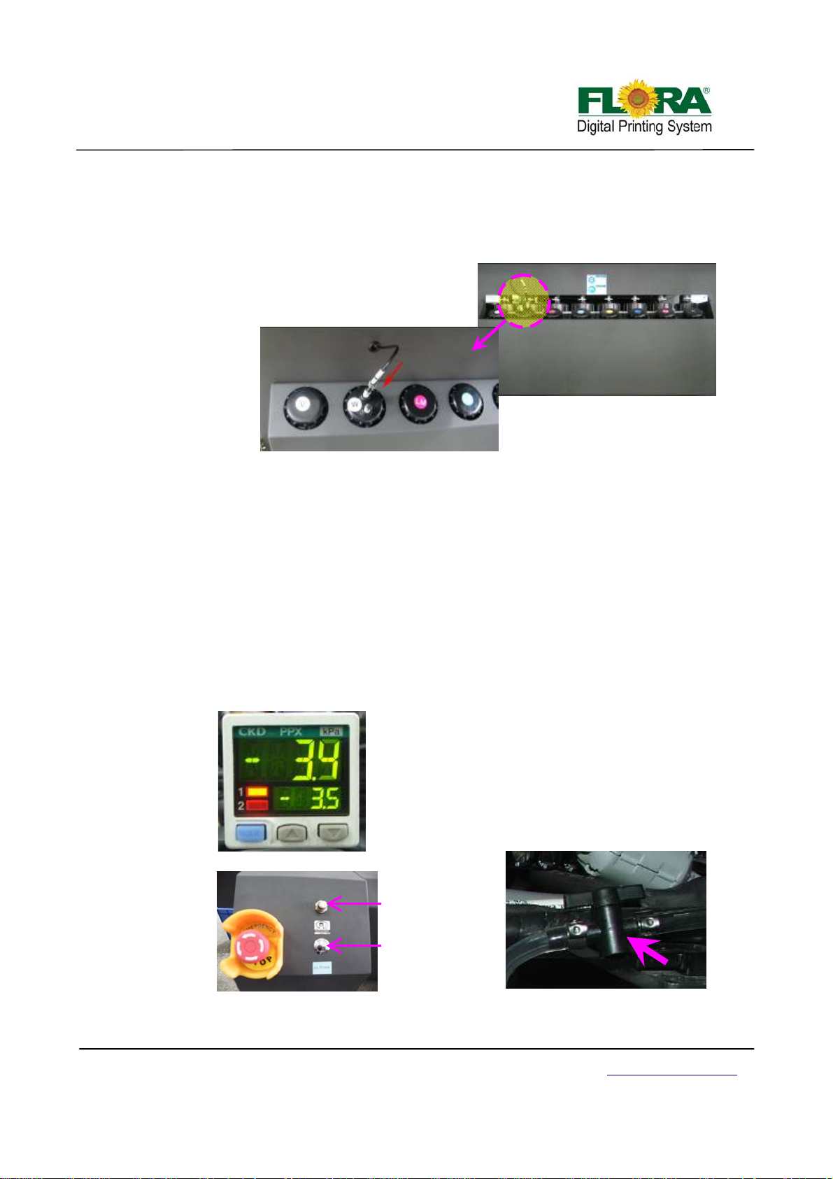
4.5.4 Negative pressure system
Negative pressure system is used to hold the ink from dripping out of the print head nozzles.
Pressure settings vary on every machine. The recommended setting range is from -2.4 to -3.0Kpa.
Too low negative pressure setting will result to ink dripping or print head cannot jet ink. Too high
negative pressure setting will cause ink starving over time and ink overflow in the negative
pressure line system.
Note:
Push the arrow up and arrow down
buttons simultaneously to reset the
negative pressure to zero.
Please refer to negative pressure setting
parameters for further details
.
Negative Pressure
Regulator
Vacuum Button
Negative pressure shut off/on
Victor Xu Page 33 12 Jan. 2011
Copyright 2011 © Shenzhen Runtianzhi Image Technology, Co., Ltd.
http://www.floradigital.com
Page 34
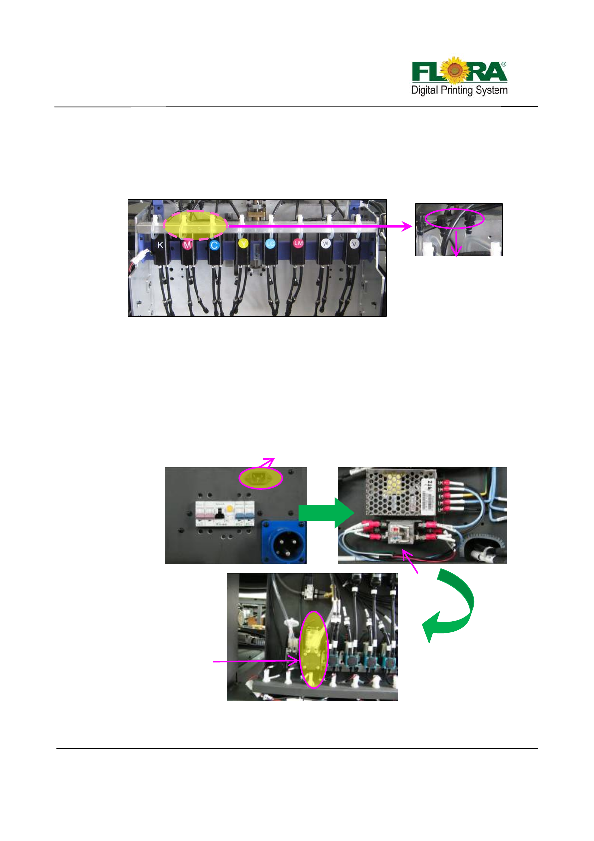
pump
4.5.5 Overflow protection system
Ink protection tank serves as the ink overflow protection for the vacuum line system. If
overflow happens, the ink will flow into this tank, once the ink reaches the maximum level, the
sensor will shut off the print head control board. Without the ink protect tank, the vacuum system
will fail to function if the tubes are filled with overflowed ink.
Front of Carriage
Note: When resetting the negative pressure to zero, open the tube connector caps. After that,
tighten cap properly.
Tube connector cap
4.5.6 External power system
This power will supply power to air pump keeping the negative pressure when the main
power of the machine is shut off.
This system will do favor to protect the nozzles from clogging.
External AC power Inlet
Relay
Negative pressure air
Victor Xu Page 34 12 Jan. 2011
Copyright 2011 © Shenzhen Runtianzhi Image Technology, Co., Ltd.
http://www.floradigital.com
Page 35
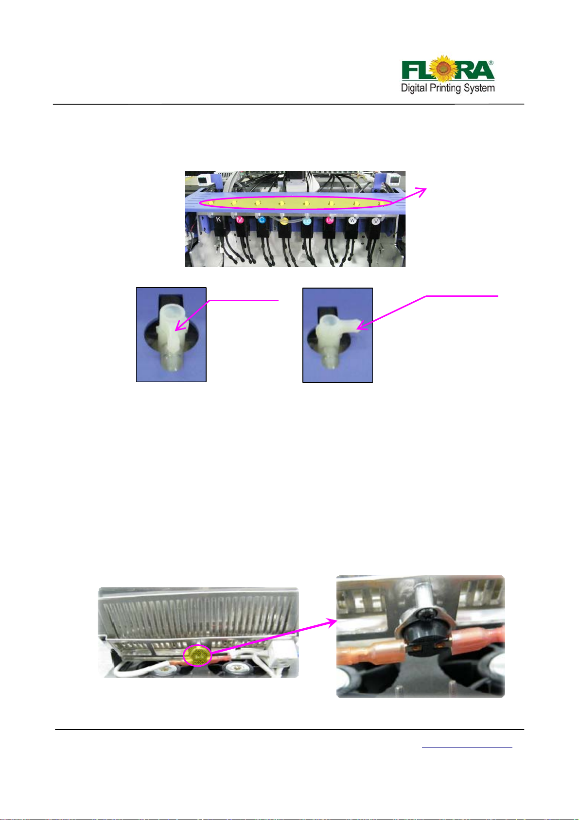
4.5.7 Individual purge system
Individual purge system allows for easy convenient respective maintenance of print head,
which will help saving ink also.
Negative position
Swap switch
Positive position
4.6 Vacuum system
4.6.1 Variable Vacuum Control System
The variable vacuum control system allows users to change the vacuum area to match the
media width to achieve the best vacuum efficiency and keep the edge of substrate from cocking.
4.6.2 Vacuum Chamber
The whole flatbed is divided into four areas. Refer to 3.4.5.
4.7 Curing system
4.7.1 Overheat protector
Overheat protector is a device to protect the UV lamp from being damaged because of high
temperature.
When the temperature in the UV house is higher than 100°C, the UV lamp will shut off
automatically. This will last the service life of UV lamp.
Overheat Protector
Victor Xu Page 35 12 Jan. 2011
Copyright 2011 © Shenzhen Runtianzhi Image Technology, Co., Ltd.
http://www.floradigital.com
Page 36
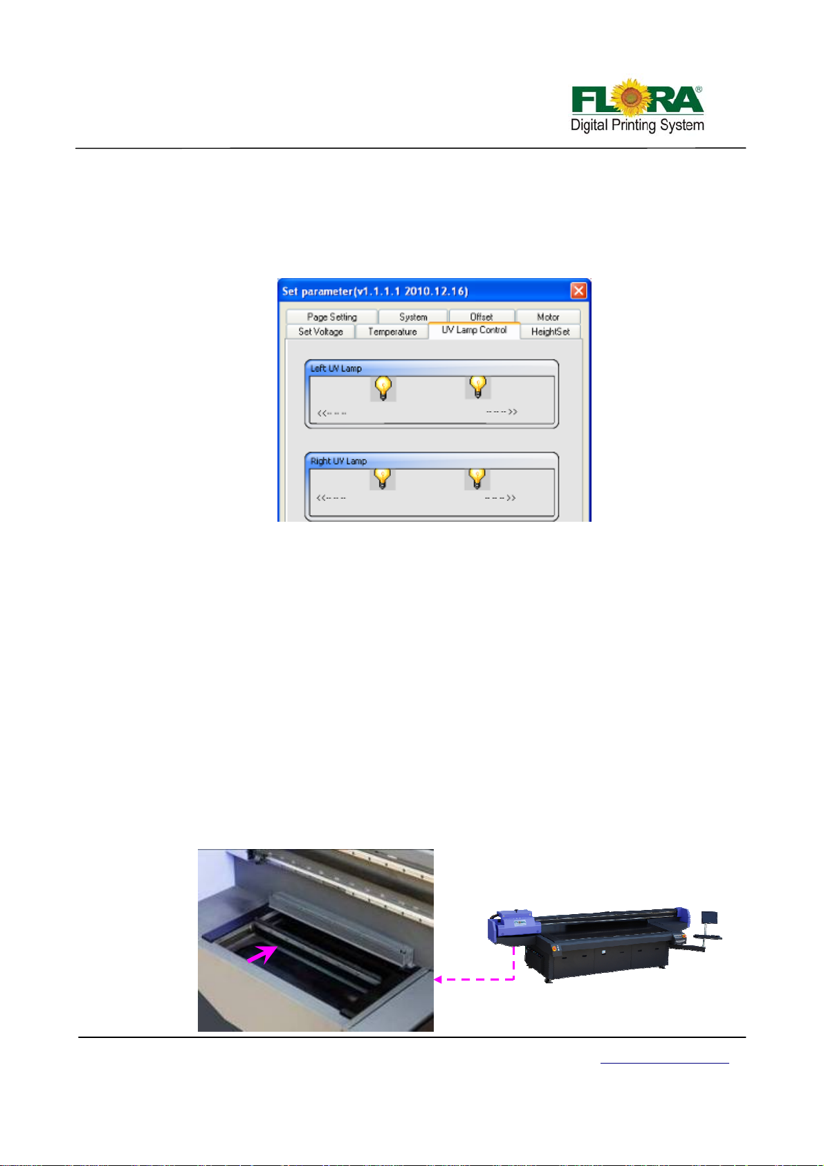
4.7.2 Intelligent curing mode
Intelligent curing mode is supply with software. Customer can choose different curing modes
for special quality.
It depends on the software to set the shutter opening and closing to achieve the function.
For more detail, please refer to 6.4.6.5
4.7.3 Two level power
The power was divided into two levels, which is selectable for different media by customer.
For the soft media like film which will be change easily with high temperature, low power
mode is better.
The high power is always used for glass or other rigid media like that.
4.7.4 UV lamp auto-shutoff function
The function is also a protection system.
When the carriage stays at the home position more than 2 minutes, the system will shut off
the high power mode automatically, and shut off the lower power whe n it is over half an hour.
During printing, unexpected stopping of the carriage happened. The UV lamp will shut off in
15 seconds avoiding burning the media and causing fire disaster.
4.8 Auto-cleaning system
Auto cleaning system allows the print head auto wiping controlled by software, which makes
the print head cleaning much more simple and timesaving. During printing, also can set up the auto
cleaning time, which will decrease the labor cost during successive printing, whilst heighten the
stability of time-unlimited printing.
Wiper
Victor Xu Page 36 12 Jan. 2011
Copyright 2011 © Shenzhen Runtianzhi Image Technology, Co., Ltd.
http://www.floradigital.com
Page 37
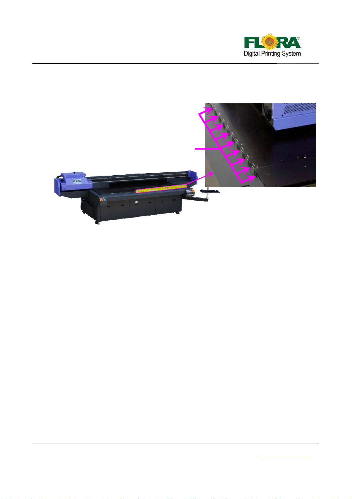
4.9 Automatic Registration Pin System
Automatic registration pin system aid easily edge to edge printing, which simplifies the
media location and ensure the high effective printing output.
Registration
Pins
Victor Xu Page 37 12 Jan. 2011
Copyright 2011 © Shenzhen Runtianzhi Image Technology, Co., Ltd.
http://www.floradigital.com
Page 38

Chapter 5 – Installation manual of Flora PP 2512UV
5.1 Pre-Installation Requirement
¾ The minimum working area should be 610 cm x 585 cm, this includes the space for the
operator to move around the machine conveniently and safely.
¾ Prepare the necessary AC plug on the power cord attached to the machine. Please see the
Technical Specification table for the power requirements.
¾ If the PC is not supplied with the machine, customer must meet the minimum PC
specification requirement to be used in this machine
9 Intel Core 2 Duo, Pentium IV 2 GHz,2G RAM, 250G Hard disk
9 DVD Drive,
9 USB Port for Hardware Key and USB cable
9 Windows XP Professional Service Pack 2
LCD monitor
9
¾ Safety signs must be available within the working area.
¾ Exhaust System must be provided for the solvent and Ink fumes. Please note that fumes
are heavier than air so it is most likely the concentration happens at the lower level of the
room.
¾ Lightings should be sufficient enough.
¾ Flammable Storage Cabinet for the Ink and flushing solution stock is highly recommended
to secure them very well.
¾ Waste Container should be available for ink and flushing liquid waste as well as ink/solvent
contaminated cloth inside the Printing area.
¾ Waste di sposal should be in accordance with your local laws governing Hazardous W aste
Disposal.
5.2 Machine Pre-Installation
Once the machine is placed and all spare parts are thoroughly checked, start doing the following
pre-installation activities;
Install the automatic Feeding and Take-up Rollers if applicable.
Removed the Tie Wire s which hold the Print head Carriage from moving.
Check the height of the Print head Carriage over the printing platform. The height should be at
least 2mm above the media printing surface.
Check the movement of the Print head Carriage for any obstruction by moving it manually from
one end to the opposite end.
Prepare the necessary power source for the machine.
Install the LCD Panel / Monitor and the PC, keyboard and mouse to be used on this machine.
Place the CPU to the computer compartment provided if applicable.
5.3 Installation of software
5.3.1 Installation Procedure of PhotoPRINT Server Flora Edition 6.1v2
1) Turn-on the Main Power to give power to the PC and Monitor.
2) Insert the CD supplied with the machine with label Photo Print 6.1V2 for the necessary
installation.
3) The screen will prompt you with 【Choose Setup Language】 window; Select which
language you will use. Then click “OK”. Then with Starting 【InstallShield Wizard…. 】
Victor Xu Page 38 12 Jan. 2011
Copyright 2011 © Shenzhen Runtianzhi Image Technology, Co., Ltd.
http://www.floradigital.com
Page 39
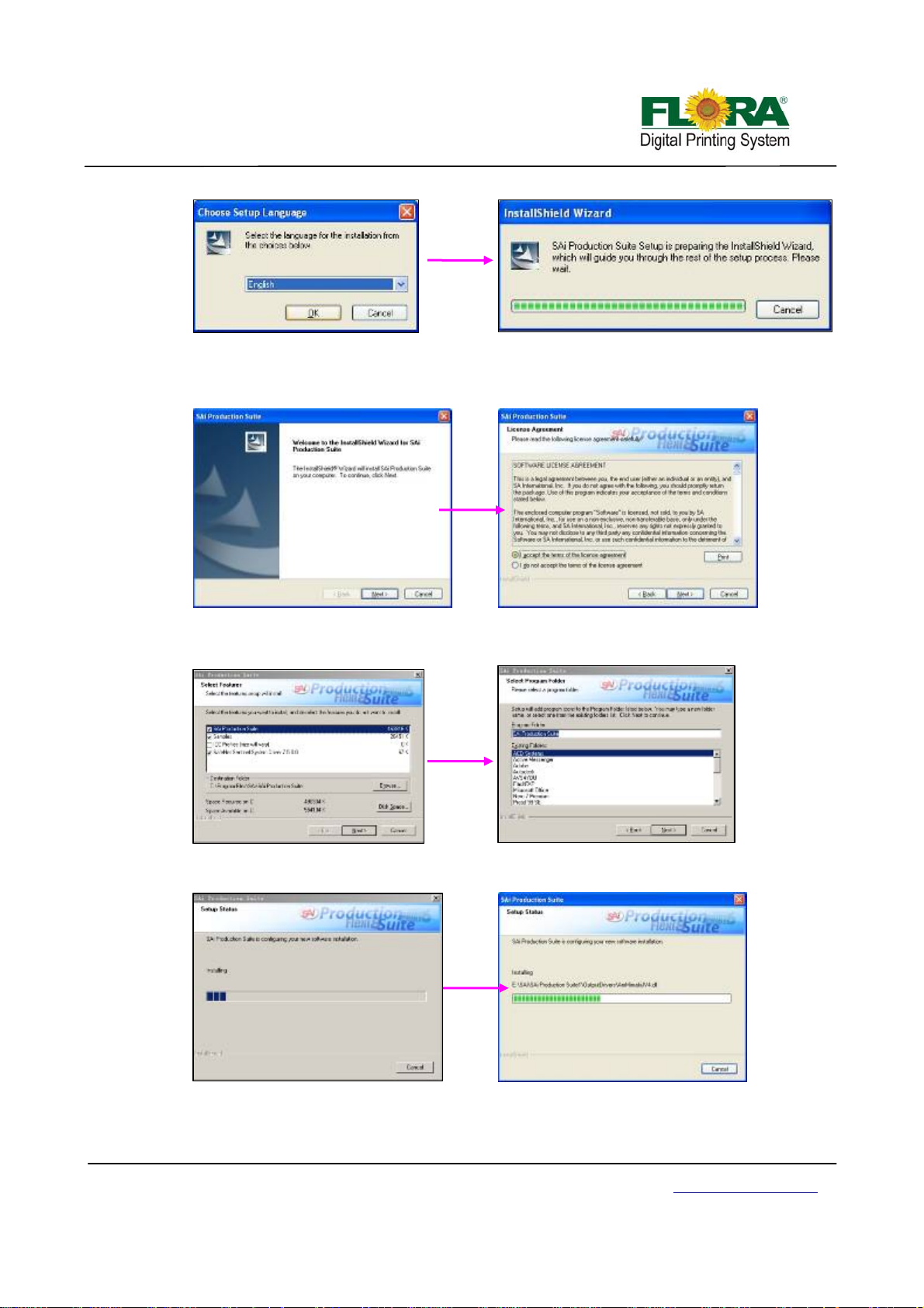
4) The Application Installer Setup will now prepare the Install Shield for the setup process,
then click “Next”. You will get a window for 【License Agreement】, please choose “I
accept the terms of the license agreement”
5) Click “Next” ,then 【 Select Features】 and the 【Select Program Folder】 screen
window will show up.
6) Then you will get a window for 【Setup St atus】, wait it finish.
Victor Xu Page 39 12 Jan. 2011
Copyright 2011 © Shenzhen Runtianzhi Image Technology, Co., Ltd.
http://www.floradigital.com
Page 40
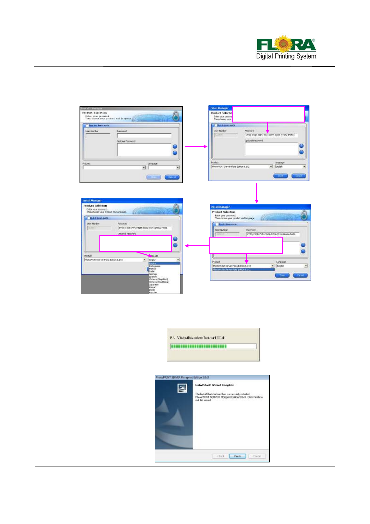
7) The 【Product Selection】 window will comes in after that. Please enter password which
you can find from the dongle. And then choose “PhotoPRINT SERVER Flora Edition
6.1v2” from product
Enter your password
Select your language
Select your product
8) Tick the “Install to desktop” selection on 【Install Manager】 window. Then click “OK”.
9) 【Start Copying Files】 window will appear. Click “Next”.
10) Click “Next”, software files will now start to install.
11) Click “Finish” after completing the successful installation.
Victor Xu Page 40 12 Jan. 2011
Copyright 2011 © Shenzhen Runtianzhi Image Technology, Co., Ltd.
http://www.floradigital.com
Page 41
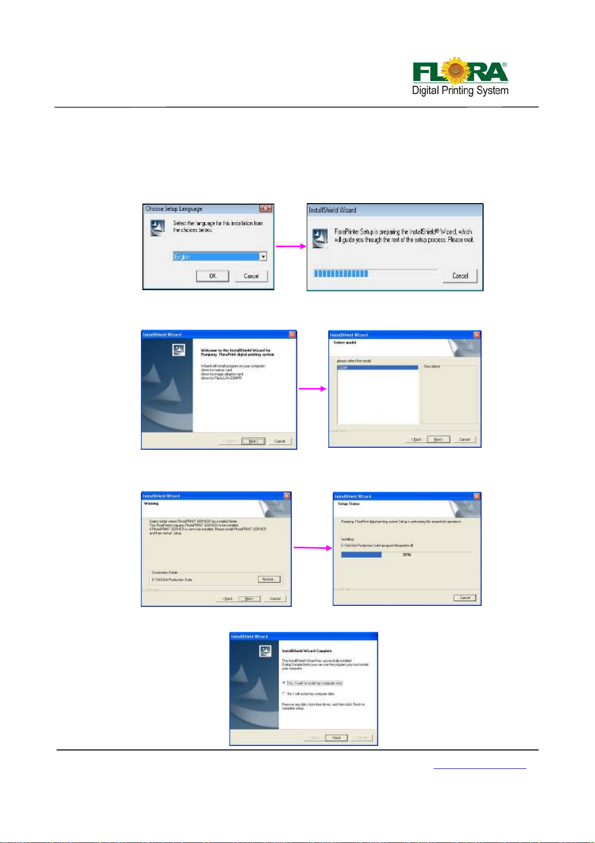
5.3.2 Installation procedure of flora driver
1) Insert the FloraPrint Driver. From the list of Folder under Print Driver, select corresponding
machine model (eg: PP2512VKM) folder. Then double-click the setup file;
2) Files will be extracted and later on 【Welcome】 window will appear. Click “Next”, coming
with 【choose setup language】 window, select you language then click “Next”;
3) Click “Next” when 【Welcome】 window. Then, 【Select Model】 window will appear.
Choose the particular model of the machine you are about to install, then click “Next”;
4) The software will now start to detect the specified destination folder, if it is not auto
detected, you need to Browse ?:\??\SAi\SAi Production Suite. Click “Next” to initiate the
installation process;
5) Click “Finish” after the successful installation and restart your comput er;
Victor Xu Page 41 12 Jan. 2011
Copyright 2011 © Shenzhen Runtianzhi Image Technology, Co., Ltd.
http://www.floradigital.com
Page 42
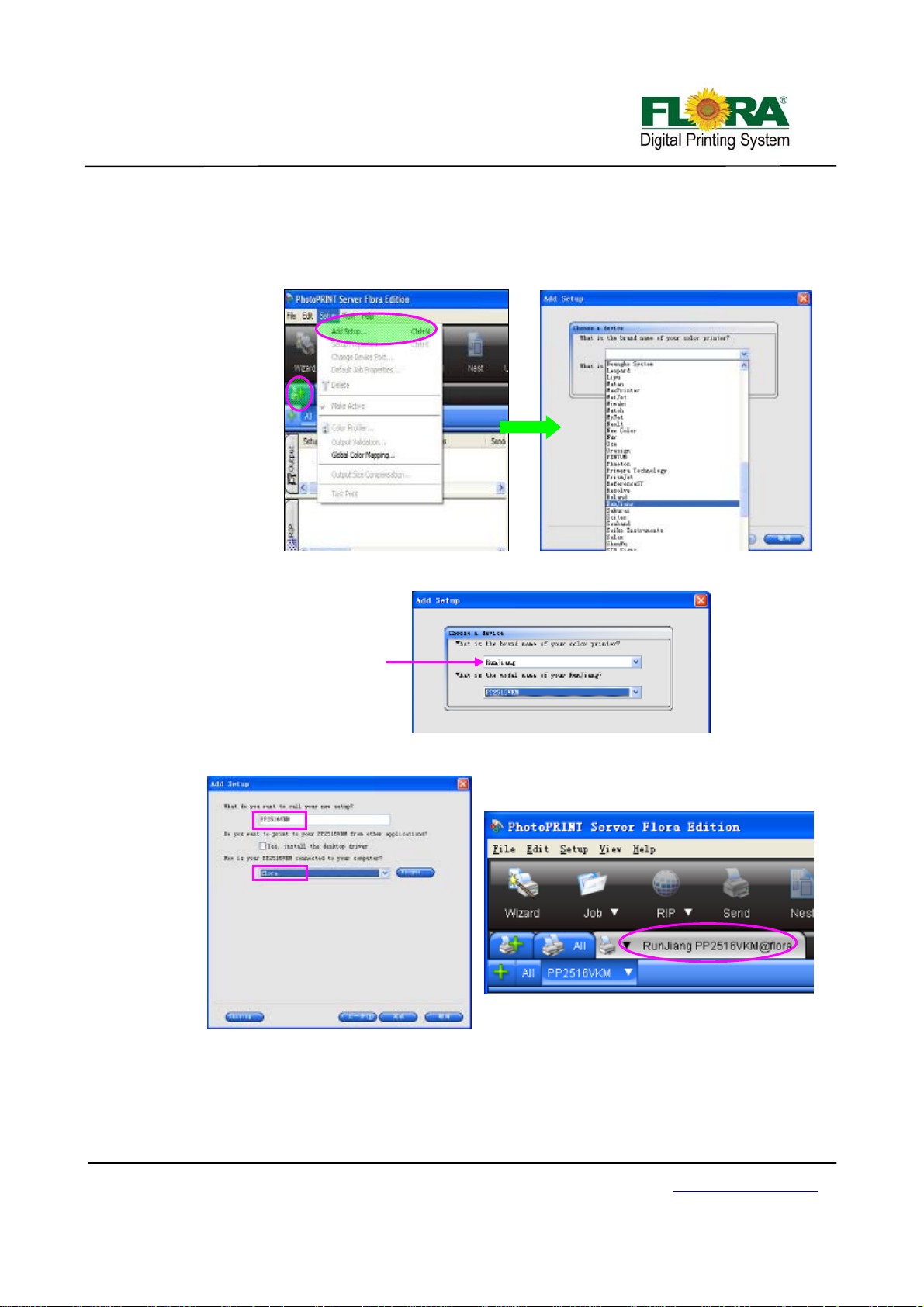
5.3.3 Add setup
1) Find the PhotoPrint 6.1 on the desktop and double click to open;
2) If it is the first time your install, it will prompt you to add your setup, or you can click “Add
Setup…” from “Setup” menu;
3) Then select the brand name of the printer and the model name. Then click “Next”;
The Brand name is
Runjiang
4) Click “Finish” after the final process. Then you can find the device
If the setup is successful the installed device or printer will be shown on the Photoprint GUI.
5.4 Install print heads
¾ Unpacking the Print head
Open the package, and then take out the anti plastic bag.
Victor Xu Page 42 12 Jan. 2011
Copyright 2011 © Shenzhen Runtianzhi Image Technology, Co., Ltd.
http://www.floradigital.com
Page 43
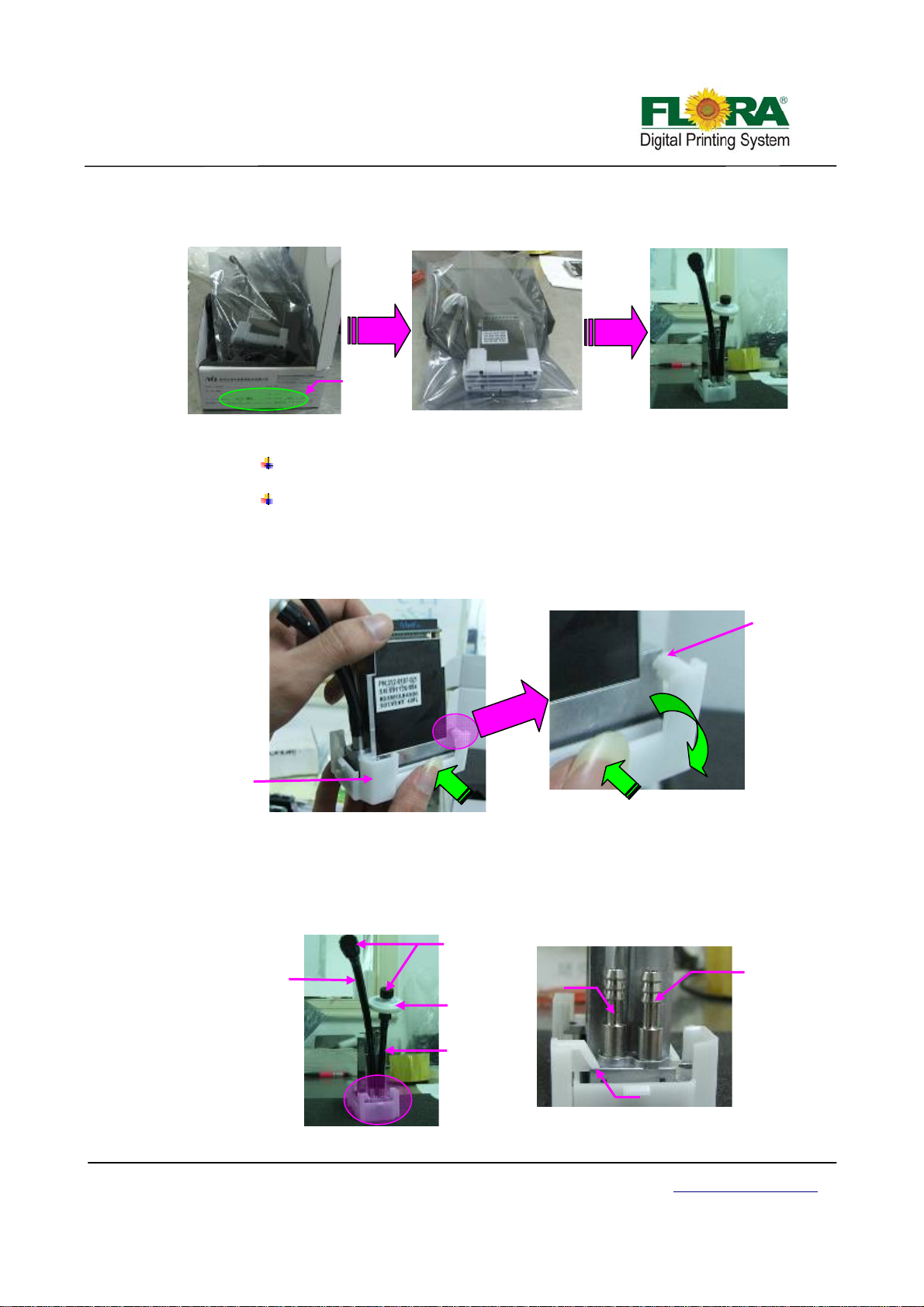
p
p
p
ort
p
Open the anti-static plastic bag and remove the head.
Remove the head cap.
Note:
The head is pre-loaded with ink analog to prevent drying of the nozzles during
transportation.
The head is also equipped with a cap to protect the nozzle surface and prevent
drying of the ink analog.
¾ Hold the middle of both sides of the cap squeeze and twist the cap to release the
latch that holds the head as shown below.
Print head
Ca
¾ Take note each print head must have input and bleeding tubing. The input tubing
Ink bleeding
tubing
How to remove cap
must be connected to the right port with disc 20µm ink filter. While the bleeding
tubing should be connected on the left port and must be closed using a connector
tube connector cap. See photo below.
The serial number
should match
Press here
Press here
Tube
Connector
ca
20µm ink
filter
Inlet
tubing
Ink bleeding
How to unlock the latch of cap
Latch
Print head Inlet and Bleeding ports
Latch is
released
Inlet
ort
Victor Xu Page 43 12 Jan. 2011
Copyright 2011 © Shenzhen Runtianzhi Image Technology, Co., Ltd.
http://www.floradigital.com
Page 44
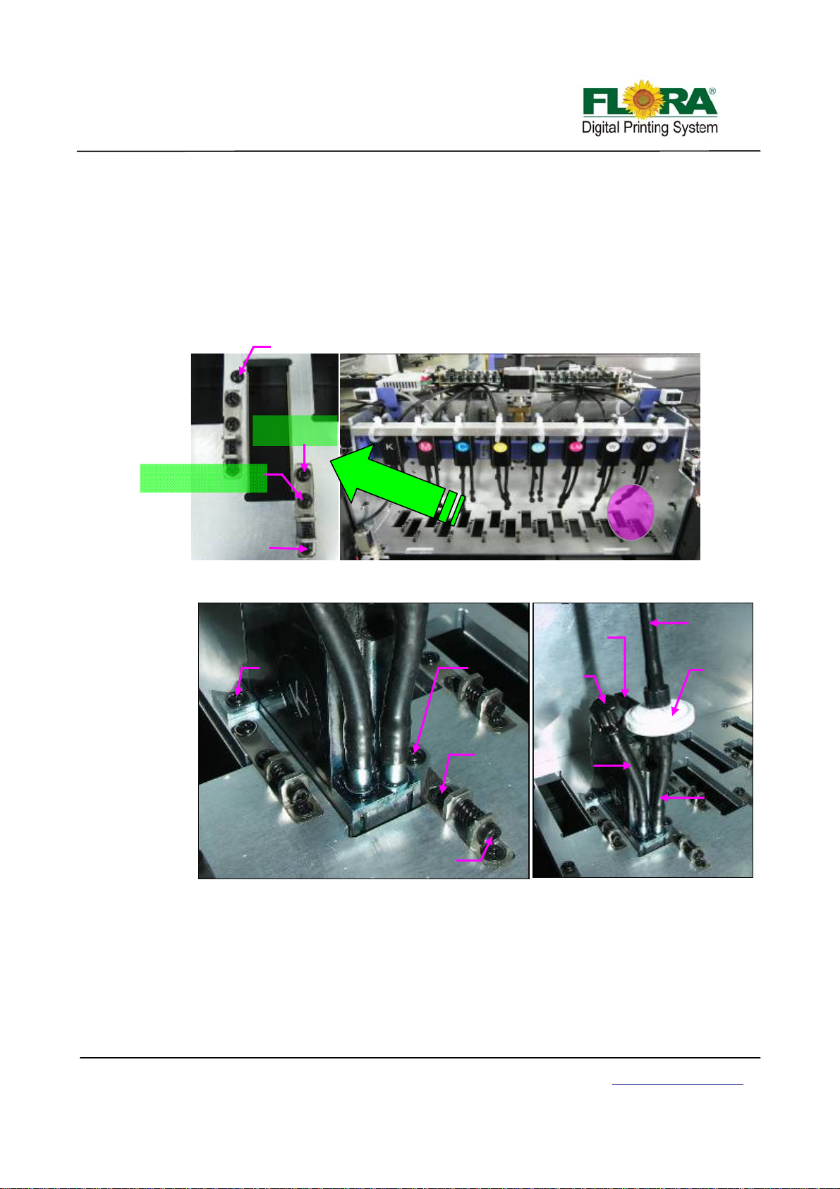
¾ Install the print head one by one by removing printhead fixation screws from the
carriage printhead mounting plate first, position the printhead and replace the two
fixation screws accordingly.
The back fixation screw must be slightly tightened to allow the printhead to move
with minimum vertical shake, while the front fixation screw must be tightened
properly before doing Y-align. Please ta ke note of proper printhead orientation.
Back Print head
fixation Screw
Front Printhead
fixation Screw
Mechanical Alignment
mechanisms lock Screw
Mechanical
Alignment
Screw
Front of Carriage with Print head
Back
Fixation
screw
Front
fixation
screw
Data Flat
cable connector
Ink bleed
tube cap
Y align
Ink bleed
mechanism
tubing
lock screw
Print head Orientation
Mechanical
alignment screw
Print head Installed on Carriage
¾ Connect the 30pins flexible print head data cable on each print head and to the
Print head Control Board. Please take note of the proper connection of cable.
Connect the input tubing of print head to the Ink tank supply port accordingly, take
note not to interchange the connection for input and the bleeding tubes. The inpu t
tubing should have a 20µm ink filter.
Printhead
input tubing
Ink disc
20µ filter
Ink Input
tubing
Victor Xu Page 44 12 Jan. 2011
Copyright 2011 © Shenzhen Runtianzhi Image Technology, Co., Ltd.
http://www.floradigital.com
Page 45
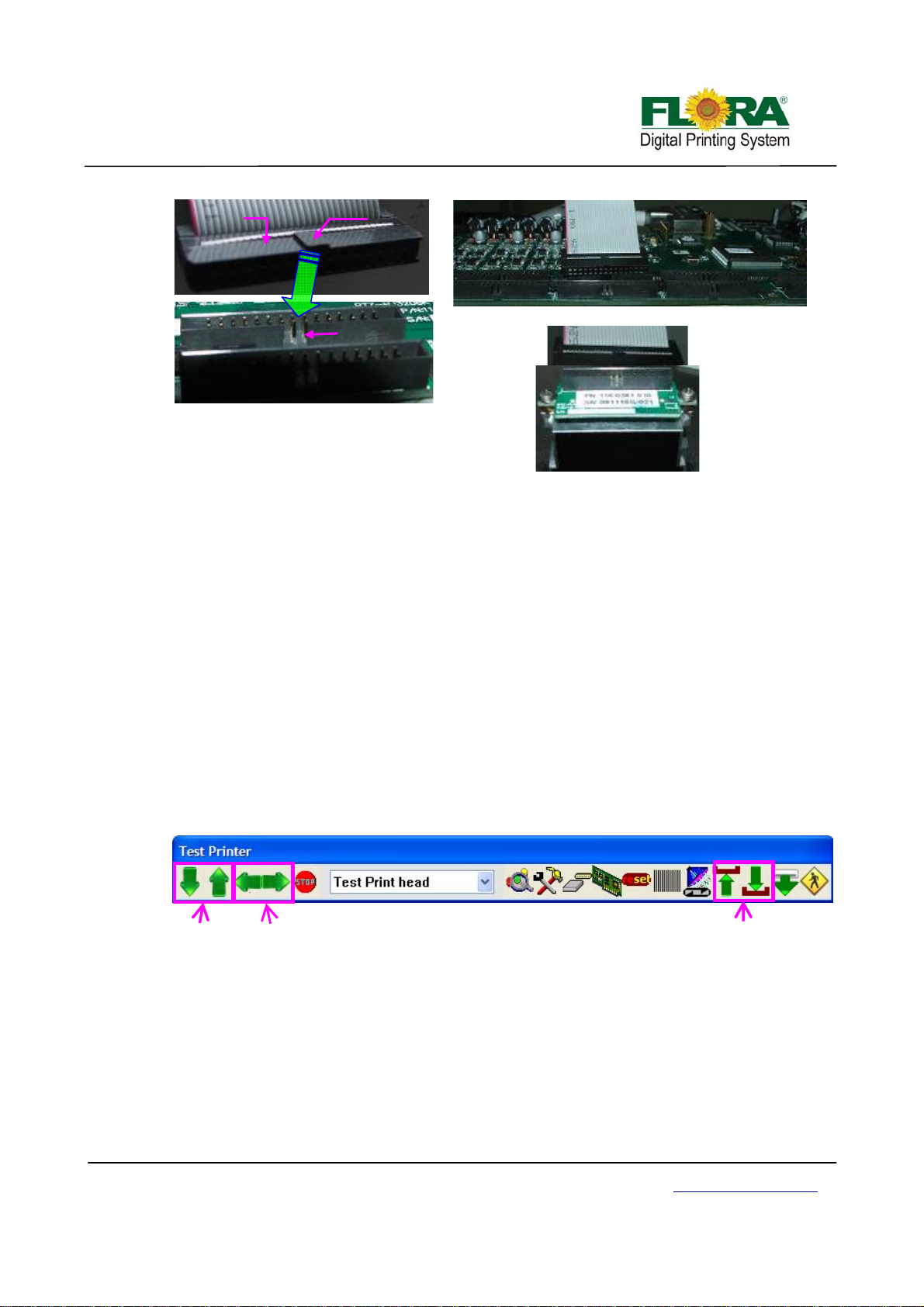
Female
Connector
Guide
Flat Data
Cable
Male connector
Connector
Slot
Print head Control Board
Flat Data Cable
Proper Connection of Flat Data Cable
Print head
Check all the connection again to ensure there are no misconnections and loose connections
on the data cables. Power on the machine and ch eck any functional abnormalities on the carriage.
5.5 Ink and Solvent Preparation
¾ Pour the ink and solvent in their corresponding ink/solvent barrels. Be sure to observe proper
procedure in handling the ink. See Chemical Safety Information
¾ Flush the print head with solvent
¾ Switch on the printer power
¾ Connect the ink pumps one at a time and check for any leakage along the solvent and ink
line system.
5.6 Test print
This is to check the mechanical functionality of the Printer through PC.
5.5.1 Test print tool bar
position. Check if the Y-axis and Z-axis Servo Motor are also working by clicking the appropriate
arrow head below. Please refer to 6.4.5 for more details.
Y-axis Icon X-axis Icon Z-axis Icon
5.5.2 Set parameter
each print head.
Using the RTZ Driver software, move the Print head Carriage from left to right, then to home
This section will describe the necessity to calibrate the Voltage and Temperature settings for
¾ By looking on the Right or X Align printed samples in section 4.9.2.3 or section 4.9.2.4
respectively you can determine what need to be done to get a better print quality.
¾ First you need to see the magnified printed sample for each print head. Let’s take the
illustration sample below.
Victor Xu Page 45 12 Jan. 2011
Copyright 2011 © Shenzhen Runtianzhi Image Technology, Co., Ltd.
http://www.floradigital.com
Page 46
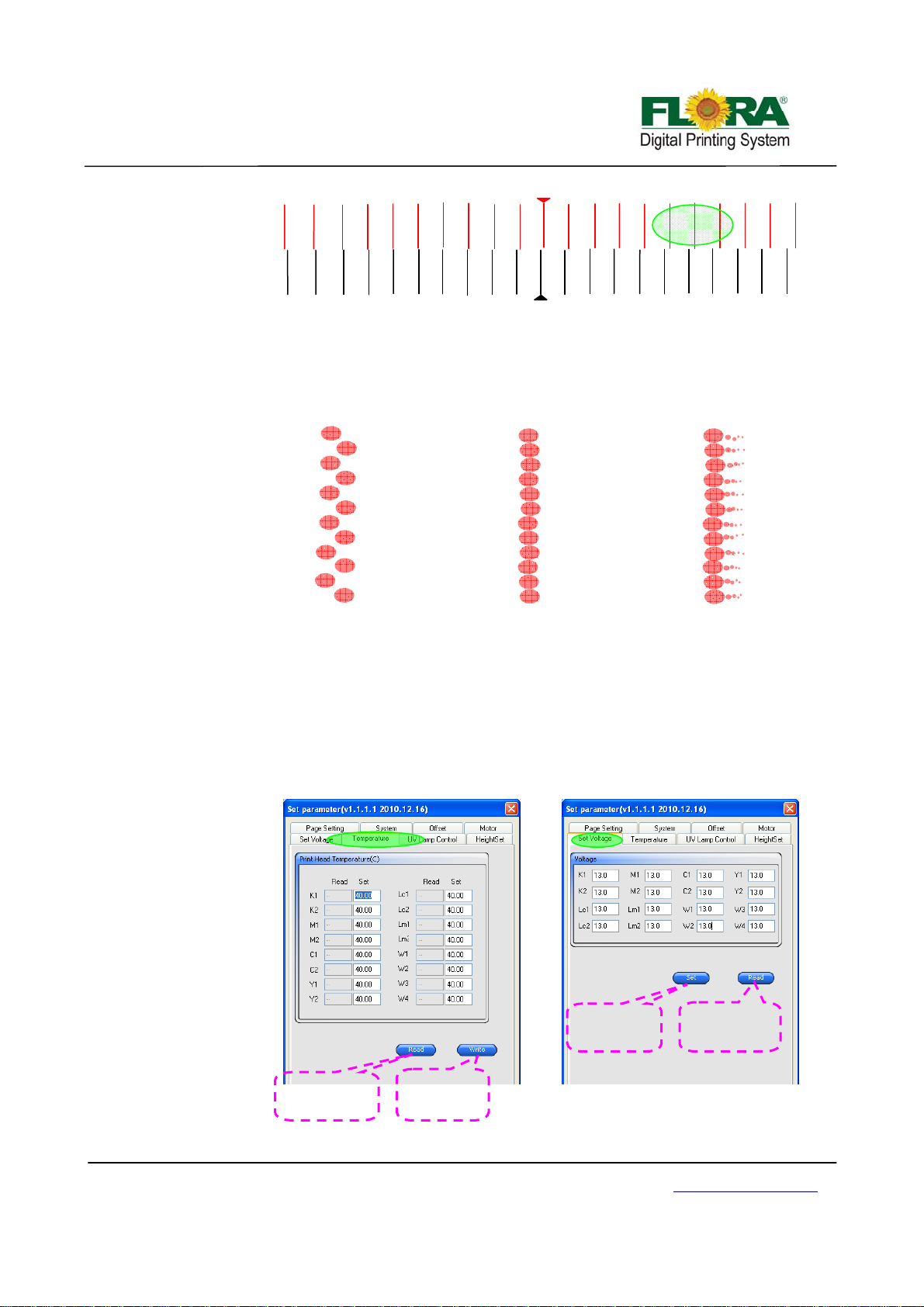
g
p
p
g
V
10
6
7
8
9
4
5
3
M1
1 -5
2
10
R I G H T
9
8
7
6
4
5
2
3
1
Ri
K1
ht Align
¾ Assuming the green shaded area will be view over a magnifying lens at least 40X
(100X magnification is better) the vertical lines are actually a group of dots pre
arranged according to print head nozzle design. For the case of Konica head it should
look like below.
Low Voltage or Low
erature Settings
Tem
GOOD
¾ Sometimes getting the best dot print quality is a painful process so it needs patience.
All you can do is play with temperature and voltage settings.
¾ The recommended Voltage setting range is controlled by Flora driver software so
there’s no chance you set the voltage beyond the recommended range. While the
recommended temperature setting is 40-45ºC in most cases ink manufacturers have
their recommended temperature settings.
¾ When changing the Voltage and Temperature settings click setting icon on the Test
Printer tab.
Click this button
to display the
actual temp
Click this
button to save
the new value
Temperature Window Tab
-2
-1
-1
-3
-2
Click this
button to save
the new value
-3
-4
-4
-6
-6
-5
High Voltage Setting orHigh
Tem
Click this button
to display the
current value
oltage Window Tab
-7
-7
Settin
-8
-8
-9
-10
-10
-9
s
Victor Xu Page 46 12 Jan. 2011
Copyright 2011 © Shenzhen Runtianzhi Image Technology, Co., Ltd.
http://www.floradigital.com
Page 47
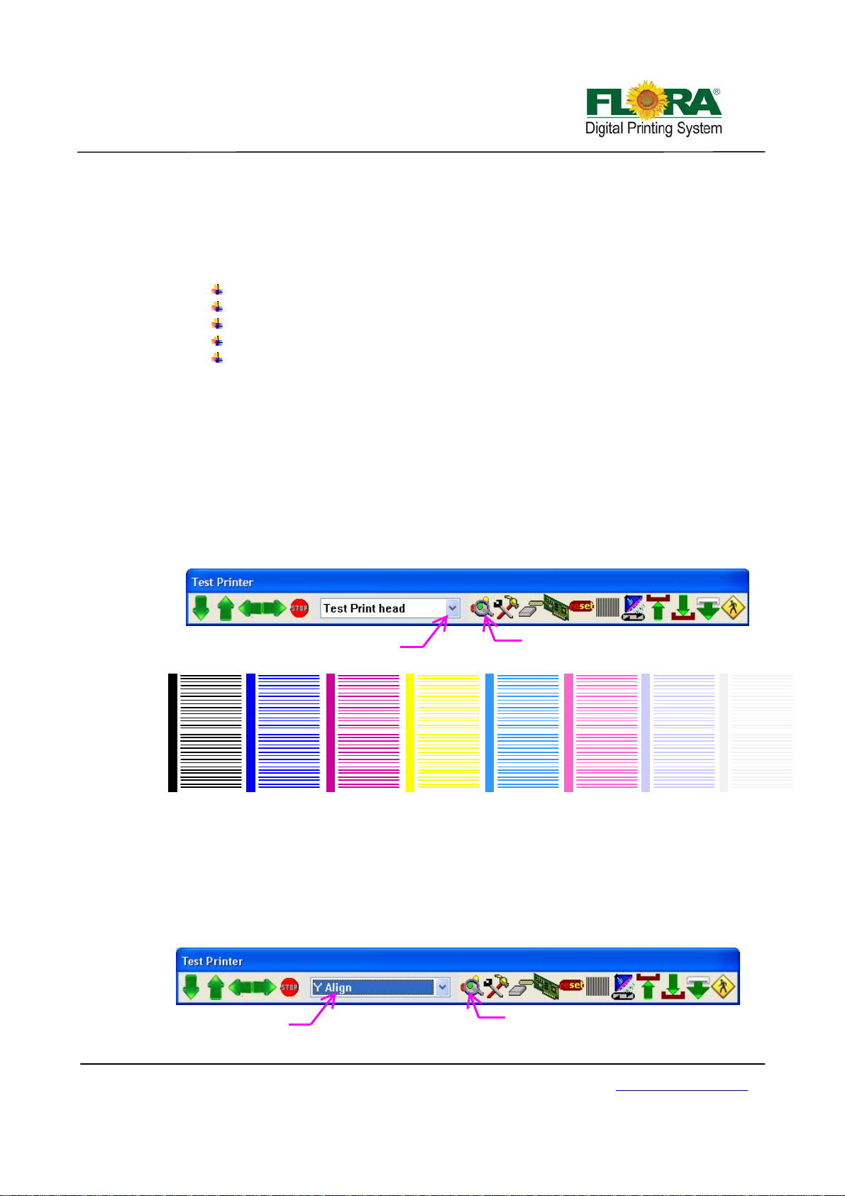
p
p
Note: The actual reading for both Voltage and Temperature will appear only when the
Read Button is click.
¾ To change the temperature setting simply over write the existing value with your
desired value then click Write button. While for Voltage you need to click the Set
button to update the Voltage setting to your desired value.
¾ Other factors than can influence print quality are:
Room Temperature
Humidity
Ink Viscosity
Negative Pressure Settings
Carriage Printing Speed
Note:
In most difficult cases playing with Uni-direction and at slower speed can help improve
the print quality significantly.
5.5.3 Print head alignment
This is to describe the proper procedure in aligning the Print heads. Before alignment ensure
the nozzle test is perfect!
¾ Perform Ink Prime by activating the toggle switch. Do ink bleeding one print head at
time to remove air bubbles trapped inside the print head.
¾ Perform auto clean for print heads thru maintenance switch on the control panel or
from the Flora driver GUI.
¾ Send Test Print head to see if all print heads prints a shown below;
Select Test Print Head
Click this to send
rint head
test
K1 M1 W1 C1 Y1 V1LC1 LM1
K2 M2 W2 C2 Y2 V2LC2 LM2
Note: Above is an Illustration of Nozzle Test Print, only three colors are shown due to
space constraint, Yellow, White and Varnish print heads must print the same result.
5.5.3.1 Mechanical Alignment (Y-Align)
¾ On Flora driver GUI, click Test Print button and on the Test Printer tab select Y-
align then click “Test print” button. The result should look as shown below.
Victor Xu Page 47 12 Jan. 2011
Copyright 2011 © Shenzhen Runtianzhi Image Technology, Co., Ltd.
Select Y-Align
Click this to send
test
rint head
http://www.floradigital.com
Page 48
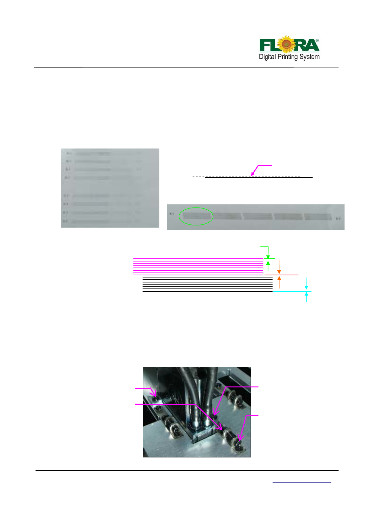
¾ Noticed there are sets of horizontal lines for K1 and K2. For the purpose of
identifying sets of horizontal lines, K1 horizontal lines are colored pink, and the
K2 is black though in actual print they are all printed black.
¾ The first sets of horizontal lines is a K1 single broken line and K2 solid line,
ignore the first 4 sets, select the rightmost set (with more horizontal lines) to get
more accurate alignment. First you must align K1 to K2. The gap between K1
and K2 horizontal lines must be the same as the spacing between all K1 or K2
horizontal lines. Please see Illustrations below.
K1 and K2 Y-align first set of Horizontal lines
This set of line is for info only
K2
Printed sample
K1
Printed sample
Gap K1
This gap should
be the same as
gap K1and K2
Gap K2
K2
¾ Once K1 and K2 print heads are aligned, tighten the two fixation screws properly.
Do Y-align to other print heads in such a way C1, M1,Y1,W1,Lm1,Lc1 and V1
will be aligned to K1 and C2,M2,Y2,W2,Lm2,Lc2 and V2 should align to K2. This
is applicable to PP2512VKMUV model only.
Note: For PP2512KMUV the V1 will be replaced by W3 while the V2 will be
replaced by W4 print heads when doing Y-align.
¾ Below shows how to do Y-alignment of the print heads.
These screws should be
slightly tighten before
doing the Y-alignment
This screw must be tightened
before doing the Y-alignment
Turn this screw clockwise to pull the
print head forward and counter
clockwise to push back.
Printhead
Victor Xu Page 48 12 Jan. 2011
Copyright 2011 © Shenzhen Runtianzhi Image Technology, Co., Ltd.
http://www.floradigital.com
Page 49
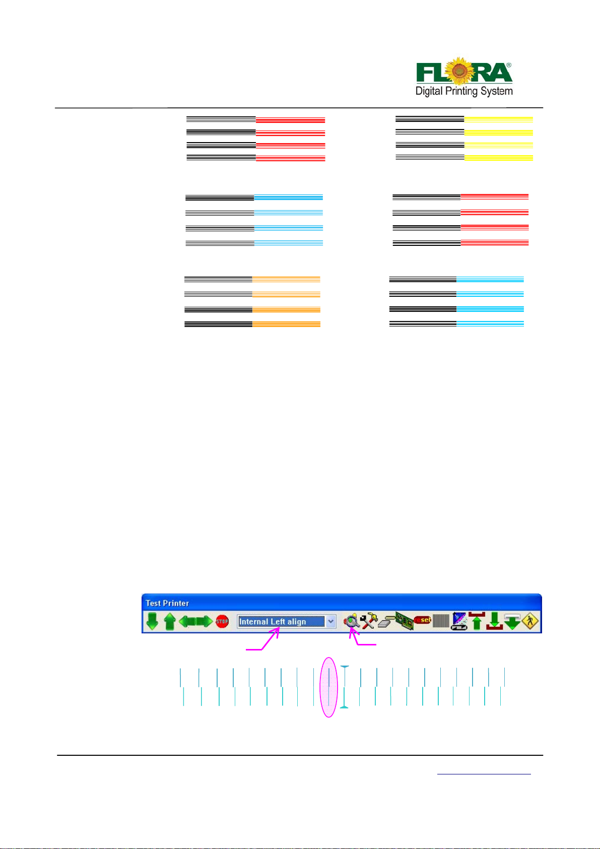
W
W
W
W
W
WKWKW
Y
Y
Y
Y
Y
p
gn
K
K
K
K
K
¾ Please take note W3 and W4 print heads Y-align are using different color just for
the sake of making the illustration easier to understand.
¾ Again due to space constraint not all print heads Y-align are shown above,
however for those other print heads you can follow the same steps.
Note:
screws for each print head.
M
Go up↑
M
M
M
Illustration for M&Y Printheads
C
Need
C
down
C
C
Illustration for C&M
↓
rintheads Y Align
Good
aligned
Align
K
K
K
K
K
K
M
Illustration for W print heads Y Align
Once the Y-alignment is completed, make sure you tighten the two fixation
M
M
5.5.3.2 Internal Alignment
Internal align is necessary for Konica heads because the Konica 512 head nozzles
are made wherein the 512 nozzles are divided into 2 parallel rows of 256 nozzles. Due to
some uncontrollable manufacturing errors (tolerances) perfect alignment is not guaranteed.
The print head internal align is required for both printing directions
Internal Left Align
¾ On the printer tab select Internal Left Align option then click send print as
shown below. Further below shows how the print out should look like, the
Illustration shows the C1 alignment happen at -1 (in-circled).
Select Internal Left align
-8
-10
-9
-7
-2
-5
-6
-3
-4
C1
-1
Click to send print
ali
1
3
2
8
6
4
5
7
10
9
-10
L E F T
-9
-8
-7
10
-5
-6
-4
-2
-3
-1
C1
1
3
4
6
5
8
7
9
Internal Left Align
Victor Xu Page 49 12 Jan. 2011
Copyright 2011 © Shenzhen Runtianzhi Image Technology, Co., Ltd.
http://www.floradigital.com
Page 50

f
gn
¾ On the Photoprint Job Properties click Driver Option >click advance button>
offset button > tick the Internal of head and add the -1 mathematically on the
Left table for C1 box as shown below.
¾ You can also navigate thru Test Printer Tab by clicking the settings icon as
shown in the lower left of Illustration.
Default value
for C1 is 0
0-1=-1
-1
Tick Internal o
Head
Internal Right Align
¾ On the printer tab select Internal Right Align option then click send print as
shown below. Further below shows how the print out should look like, the
Illustration shows the M1 alignment happen at 2 (in-circled).
Select Internal Right align
Click to send print
ali
10
8
9
6
7
4
5
3
M1
1
2
-2
-3
-1
-4
-5
-6
-7
-8
-9
-10
¾ On the Photoprint Job Properties click Driver Option >click Advance button>
¾ You can also navigate thru Test Printer Tab by clicking the settings icon as
R I G H T
10
7
9
8
6
4
5
2
3
1
-1
M1
-3
-4
-2
-5
-6
-7
-8
-9
-10
Internal Right Align
Offset button > tick the Internal of Head and add the 2 mathematically on the
Right table for M1 box as shown below.
shown in the lower left in Illustration below.
Victor Xu Page 50 12 Jan. 2011
Copyright 2011 © Shenzhen Runtianzhi Image Technology, Co., Ltd.
http://www.floradigital.com
Page 51
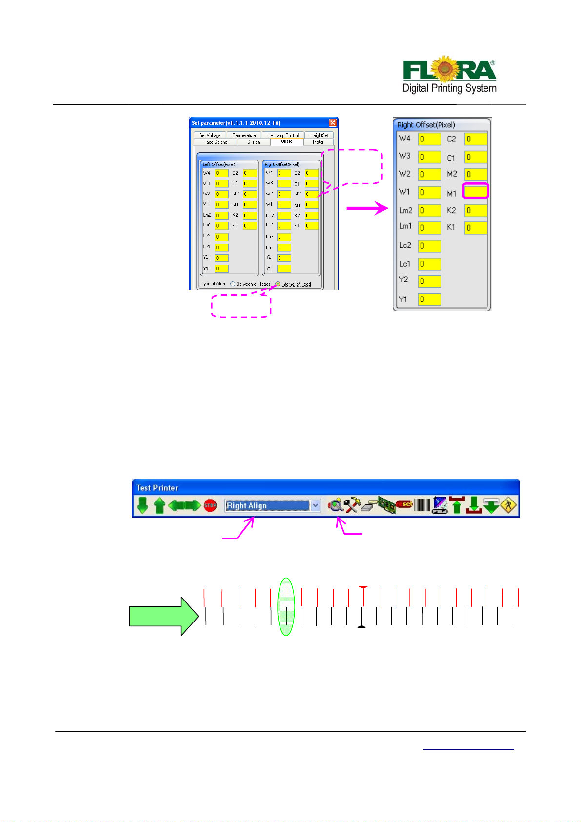
f
gn
Default value
for M1 is 0
0+2=2
2
Tick Internal o
head
¾ Follow the same steps when doing Internal of head alignment for other print
heads not shown in the Illustration above.
5.5.3.3 Right Align
There are 16 print heads in 8 colors in total. As they are fixed in different physical
position, it is necessary to do Right Alignment for secondary colors, or the secondary color will
be fuzzy and the output picture will be rough. Here this machine takes K1 as the base to alig n
the other print heads.
¾ On the printer tab select Right align option then click send print as shown below.
Further below shows how the print out should look like, the Illustration shows the
M2 alignment happen at 5 (in-circled). Please note that this time K1 is the
reference print head in aligning all other print heads.
Select Right align
Click to send print
ali
10
8
9
6
7
4
3
M2
1 -5 5
2
-2
-3
-1
-4
-6
-7
-8
-9
-10
K1 is Reference
Head
10
R I G H T
9
8
7
4
6
5
2
3
1
-1
K1
-3
-4
-2
-5
-6
-7
-8
Right Align
¾ On the Photoprint Job Properties click Driver Option >click Advance button>
Offset button > tick the Between of Heads and add the 5 mathematically on the
Right table for M2 box as shown below.
¾ All the other colors are will be aligned in the same way.
-10
-9
Victor Xu Page 51 12 Jan. 2011
Copyright 2011 © Shenzhen Runtianzhi Image Technology, Co., Ltd.
http://www.floradigital.com
Page 52
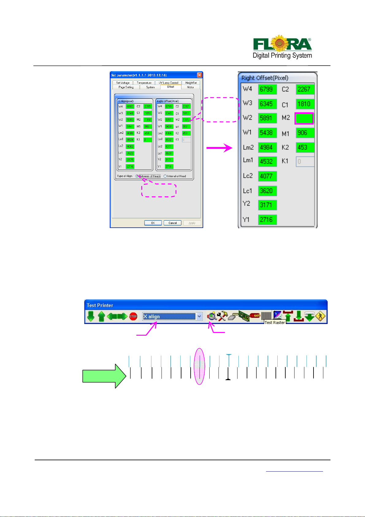
gn
Default value
of C1 is 1361
1361+5=1366
1366
Tick Between
of heads
5.5.3.4 Print head X Align
X alignment is very necessary for Bi-direction print mode. If this alignment is not good,
the output image will be rough and fuzzy because of dislocation output coming from double
directions.
¾ On the printer tab select X align option then click send print as shown below.
Further below shows how the print out should look like. The Illustration shows
the C1 alignment happen at -3 (in-circled). Please note that this time K1 is the
reference print head in aligning all other print heads.
Select X align
-10
-9
-8
Right
-7
-5
-6
-3
-4
-2
Click to send print
ali
C1
-1
1
8
6
4
3
2
5
7
10
9
K1 is Reference
Head
-10
-9
Left
-8
-7
-6 -5 -4
-2
-3
-1
K1
1
3
5
4
7
6
8
X Align
¾ On the Photoprint Job Properties click Driver Option >click Advance button>
Offset button > tick the Between of Heads and add the -3 mathematically on the
Left table for C1 box as shown below.
¾ All the other colors are will be aligned in the same way.
10
9
Victor Xu Page 52 12 Jan. 2011
Copyright 2011 © Shenzhen Runtianzhi Image Technology, Co., Ltd.
http://www.floradigital.com
Page 53
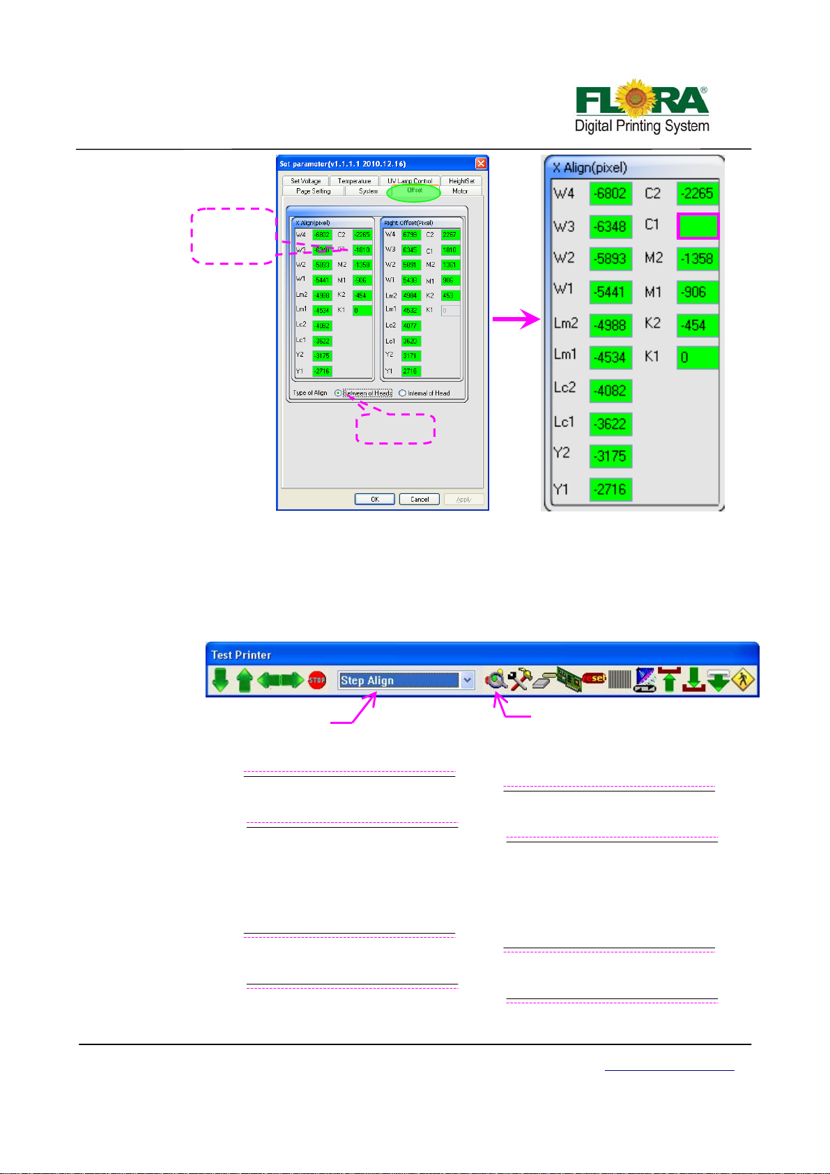
g
p
gn
Default value
of C1 is -1810
-1810-3=-1813
-1813
Tick Between
of heads
5.5.3.5 Step Align
¾ On the printer tab select Step Align option then click send print as shown below.
Further below shows how the print out should look like. The Illustration shows
three different scenarios.
¾ The broken line was colored pink for the purpose of better understanding, the
horizontal lines are printed black in actual output. When you do step align the
first pass will print broken lines while the second pass will print the solid lines.
Select Step Align
Fi
ure 1 –Insufficient Feeding Step
¾ Figure 1 shows the motor step value when the test was sent is higher than exact
value so we need to increase, by trial and error method you can get the correct
value.
Figure 2 –Excessive Feeding Ste
Click to send print
ali
Victor Xu Page 53 12 Jan. 2011
Copyright 2011 © Shenzhen Runtianzhi Image Technology, Co., Ltd.
http://www.floradigital.com
Page 54
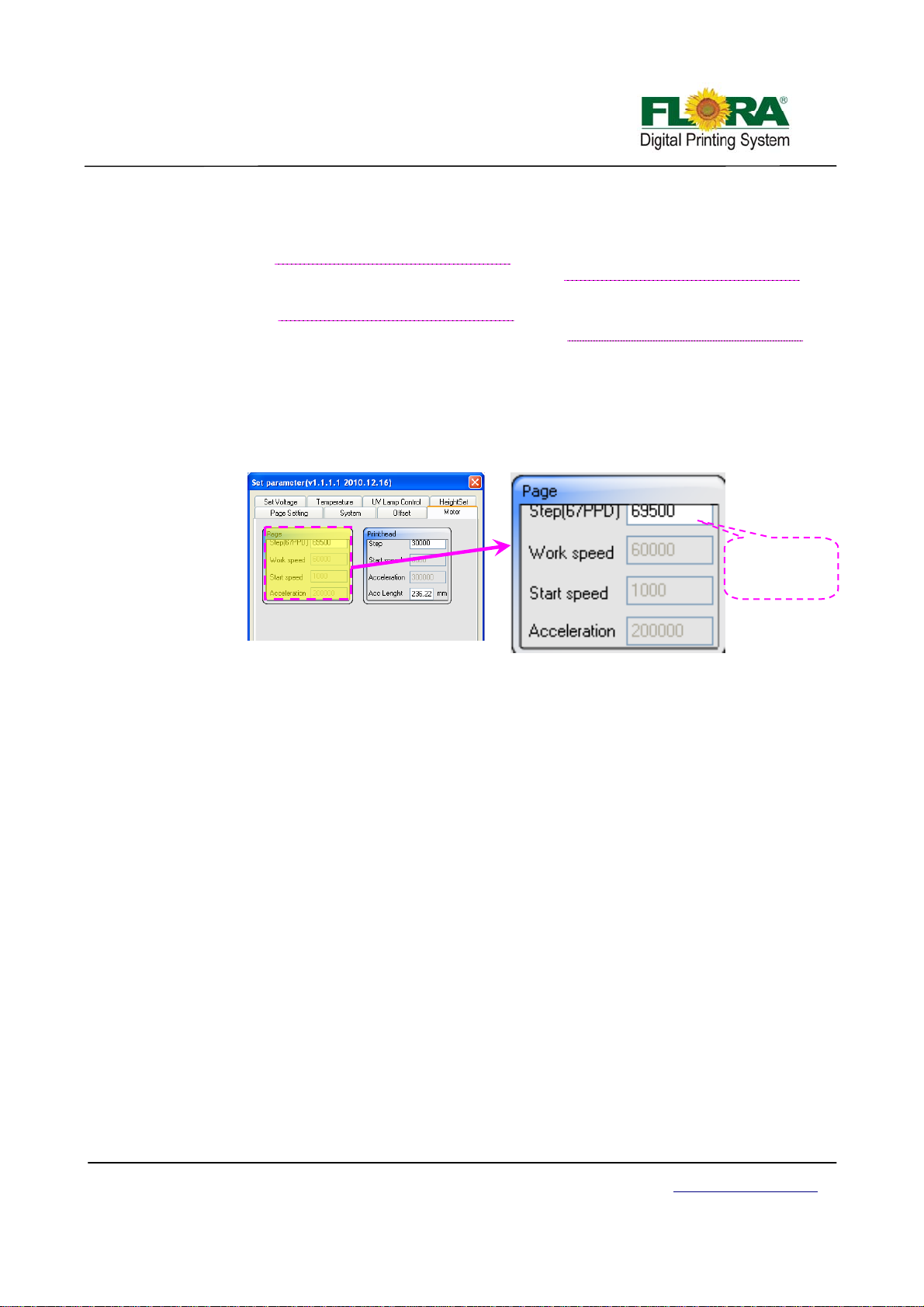
C
g
¾ Figure 2 shows the motor step value when the test was sent is lower than exact
value so we need to decrease, by trial and error method you can get the correct
value.
¾ Figure 3 shows the motor step has exact value so no need for any changes. To
determine the exact motor step value setting, you need to bring the broken and
solid lines closer until you can see one single line only.
¾ Below is the table where you can find the Step Parameter setting.
Motor Step Parameter Tab
Fig. 3 – Correct Media Feeding Step
Enlarged View
hange this
number to
et the
exact motor step
value
Victor Xu Page 54 12 Jan. 2011
Copyright 2011 © Shenzhen Runtianzhi Image Technology, Co., Ltd.
http://www.floradigital.com
Page 55
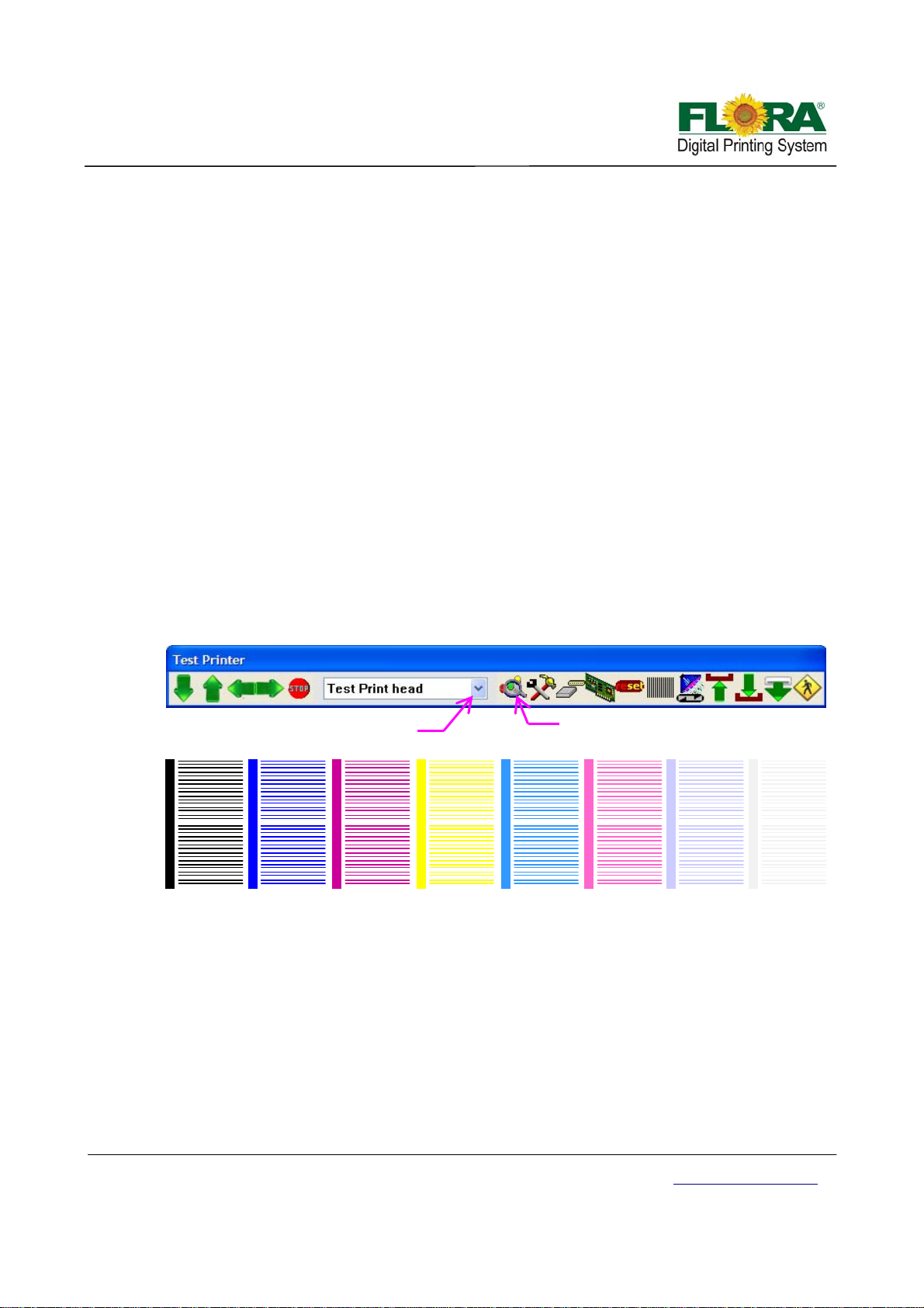
p
Chapter 6 -Operation manual of Flora PP 2512UV
6.1 Brief Introduction
This chapter introduces the details of operating the operating instru ctions of the machine from
starting up to shutdown procedure.
6.2 Starting-up Activities
It is highly recommended to do housekeeping before starting to operate the machine. Maintaining
good housekeeping helps improve the quality of the output as well as the safety of operator. Below is
the check list of activities that operator should do prior to operation of the machine.
9 Turn on the ventilating and lighting system inside the printing room.
9 Check and clear for any traces of ink spillage on the machine and the floor.
9 Check if the Waste Ink Bottle is already full and replace if necessary
9 Check if there is enough inks for printing and flush solution for cleaning the print head.
9 Check and ensure that the printing platform along the print head carriage path is free from
loose parts or obstructing object
9 Turn on the Main Power Switch and power-on the PC.
9 Turn on the Printer Power
9 Check the Negative Pressure setting
9 Perform Ink Priming procedure on the Print head
6.3 Print head Jetting Check
Check the jetting status of each Print head periodically before, during and after using the machine.
Select Test Print Head
K1 M1 C1 Y1 V1LM1
K2 W2 C2 Y2 V2LM2M2
Note:
Please take note that all print heads must print the same. If not, do purge or flush the print
heads.
6.4 Operational approach of PhotoPrint
6.4.1 PhotoPrint Job Folder
Figure below shows the current job list and statuses, the printer mo del, add job icon and
other printing instructions. It is divided into three queues:
Printing job queue shows the jobs that are currently printed and those queued for printing.
Ripping job queue shows the jobs that are under ripping process, have complete d the ripping
process and those ready to be sent for printing.
Click this to send test
rint head
LC1
LC2
W1
Victor Xu Page 55 12 Jan. 2011
Copyright 2011 © Shenzhen Runtianzhi Image Technology, Co., Ltd.
http://www.floradigital.com
Page 56
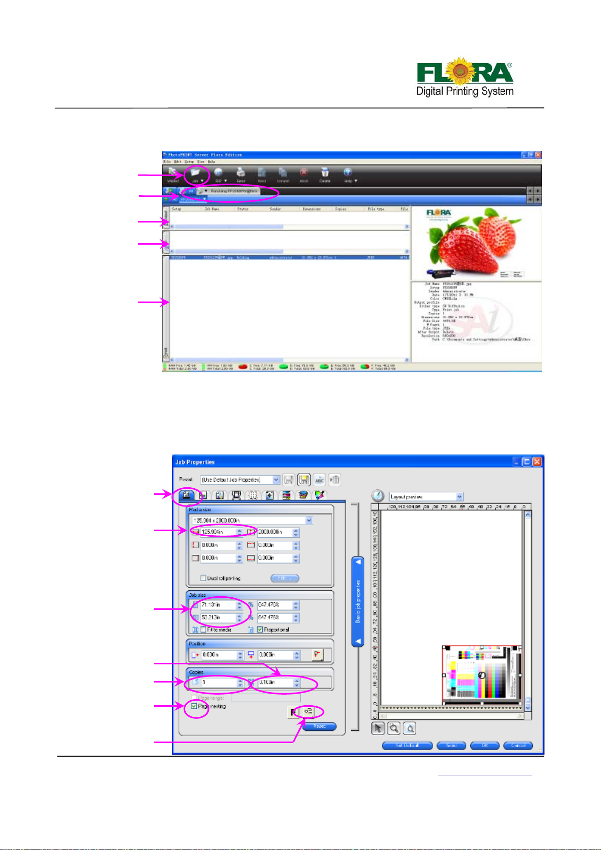
p
y
q
q
q
Job queue shows the list of all jobs that have been printed, aborted, ripped and new added
jobs waiting to be sent for editing or ripping.
Add job
icon
Printer
model
Printing job
ueue
Ripping job
ueue
Ripping job
ueue
6.4.2 Editing the Image
Figure below shows the image layout parameters like: printing size, margins, number of
copies and orientation of image. This is the first window that will pop out every time you click the
job or default job properties. After editing you can directly send the job for printing by clicking send
button or send for ripping by clicking OK button. Clicking the reset button will change all the
parameters back to default settings. Other parameters shown on this window are self- explanatory.
Lay out tab
Media max
size
Image size
Space between
co
ies
No of copies
Nesting check
box
Image orientation
button
Victor Xu Page 56 12 Jan. 2011
Copyright 2011 © Shenzhen Runtianzhi Image Technology, Co., Ltd.
Out Window
La
http://www.floradigital.com
Page 57

6
6.4.3 Work Flow Tag
Figure below shows the option what to do with the job file after printing. There are three
options available for the end users:
¾ Delete – the image will be lost after printing is completed
¾ Hold – the image will be retained in the job folder after printing is completed
¾ Archive – the image will be sent in archive folder after printing is completed
Notice: Click OK button after you select from the option.
Work flow
tab
Work flow
box
Choose
hold
Click OK
6.4.4 Color Management Tag
Figure below shows the image printing parameters in terms of resol ution, ripping quality,
type of media, ICC profile and others. Detail explanations can be read in PhotoPrint manual, which
is available after the RIP sof t ware has been installed in the PC.
Click OK button or send button if all parameters are finalized.
1
2
3
4
5
Spot white must
un-tick this box
Victor Xu Page 57 12 Jan. 2011
Copyright 2011 © Shenzhen Runtianzhi Image Technology, Co., Ltd.
http://www.floradigital.com
Page 58
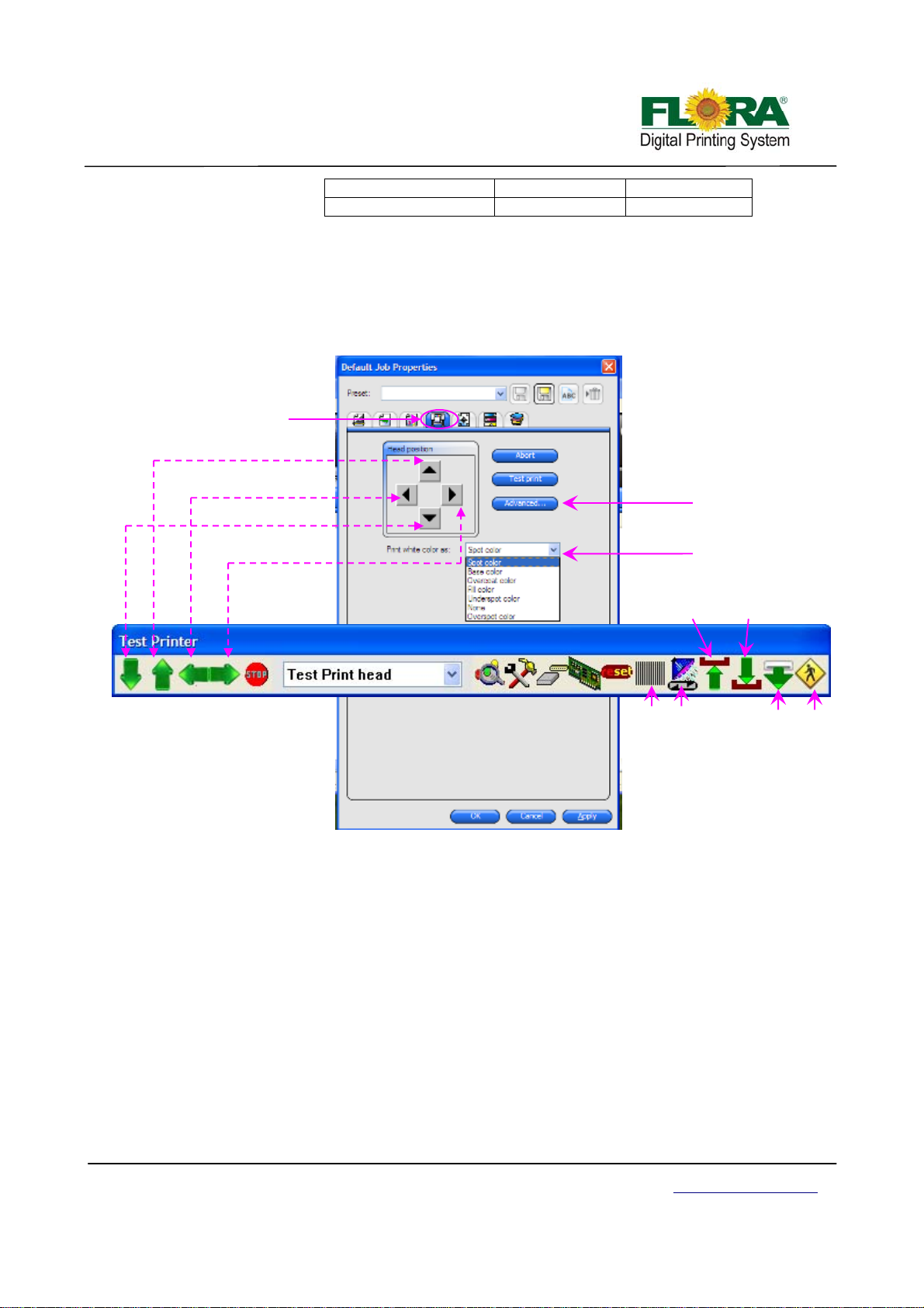
1,Color correction Box 2,ICC check box 3,Media check box
6.4.5 Test Print Tag
This test is being performed in order to verify the conditions of the Print head nozzles before
printing. It prints a swatch which could represent the nozzles to be firing on a definite order.
From the FloraPrint driver window , select “Test Print head” the drop-down list cli ck on the
“Align colors” button.
4,Resolution option box 5,Color mode box 6,Dither type box
Test print tag
Media move backward
Carriage move to left
Media move forward
Carriage move to right
Refer to 6.4.1
White color mode
Carriage
up
Carriage
down
Raster
test
Auto
clean
Back to
origin
Exit
6.4.6 Advance Button
Figures below will pop out when you click the advance button under job properties printer
option. The following pop out windows representing a printing parameter setting. They will appear
as soon as you click their designated button.
6.4.6.1 Page setting Tab
Ribbon:
-left: when this check box activated, the machine will print ribbon on the left side
of the image.
-right: when this check box activated, the machine will print ribbon on the right side
of the image.
-Width: set the width of the ribbon
-Spa ce with image: define the space between ribbon and the image
Default setting:
-Media’s width: define the maximum size of the image can be printed
Victor Xu Page 58 12 Jan. 2011
Copyright 2011 © Shenzhen Runtianzhi Image Technology, Co., Ltd.
http://www.floradigital.com
Page 59
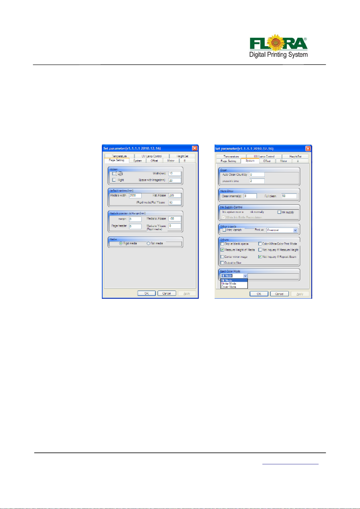
-Flat X-base: define the mechanical position start to print on X-axis
-Flat Y-base: define the mechanical position start to print on Y-axis
Media’s position & Margin:
-margin: keep the margin on the media
-Media to X-base: set the counter-position to print
-Page header: keep header space on the media
Media:
-Rigid media: if the media is rigid media, choose this radio button
-Roll media: if the media is roll media, choose this radio button
6.4.6.2 System Tab
Clean:
-Auto Clean Count by: the clean times can be set in this text box
-Press ink time: priming time can be set in this text box
Micro Drop:
-Clean internal(s): this used to set the micro drop cycle
-Full clean: this used to set the drop size of the micro drop
Ink Supply Control:
-ink supply check box: if tick this box, the pump will supply ink until the sub-tank is
full, or the pump will stop working within 15 seconds
Other liquids:
-Print Varnish check box: Varnish can only be printed when this ch eck box
was ticked.
-Print as drop down list: choose color mode from here
Others:
-Skip at blank space check box: Tick this box, the printer will skip over the
blank space then start to print.
-Color-White-Color Print Mode check box: Tick this box, the printer will print at 3
layers mode.
Victor Xu Page 59 12 Jan. 2011
Copyright 2011 © Shenzhen Runtianzhi Image Technology, Co., Ltd.
http://www.floradigital.com
Page 60

-Measure Height of media check box: Tick this box, the software will
measure height at every time before print a job.
-Not Inquery if Measure Height check box: Un-tick this box, it will pop out the
dialog box as below:
-Center mirror image & Output to files check box: there is no use here.
-Not Inquery If Reposit Beam check box: Tick this box, it will pop out a dialog
box as below to ask if back to home position.
Spot color mode:
-Spot color mode drop-down list: This is used to white mode under spot color mode.
For internal Right and
left alignment
For X Align and Right
Offset alignment
Victor Xu Page 60 12 Jan. 2011
Copyright 2011 © Shenzhen Runtianzhi Image Technology, Co., Ltd.
http://www.floradigital.com
Page 61
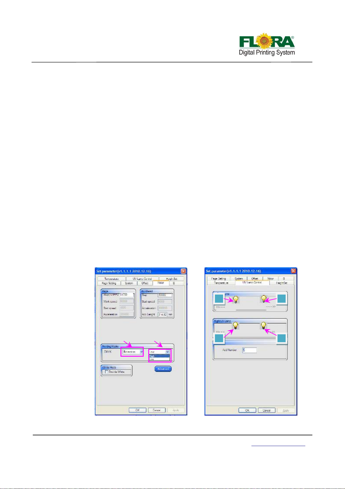
6.4.6.3 Offset Tab
The tab supplies text box for soft ware alignment. Please refer to for more details.
6.4.6.4 Motor Tab
Page:
-Step (111PPD): this text box used to change page feeding step
Print head:
-Step: this text box used to set the carria ge moving step when clicking right moving
icon on test print tool bar.
Printing Mode:
-CMYK: choose mode from drop-down list, including speed and direction
Advanced:
-Printing Speed: choose the same speed with the motor window. Low speed will scan
more dots, so on X-axis direction, it will print high resolution.
-Resolution: The DPI or dots per inch of an image. Measured by how many dots or
pixels are in one inch of a design. It is a measurement of the fineness or detail. The
higher the resolution is, the finer the detail in an image.
-Extract: extract dots from original design and print more passes wi th the same ink
limited. This will control the print head to jet ink dots on the media more averagely,
which will be helpful to improve the pass banding and other banding coming with
clogged nozzles.
-Repeat: repeat printing double, triple, quadruple times. More repeat times makes
darker image output. Please refer to PhotoPrint Flora Edition Software.
White Mode:
-Double White check box: The mode can only be used unde r uni-direction mode. It
will print white ink when the carriage comes from left to right.
1
Direction Speed
2
4 3
6.4.6.5 UV lamp Tab
Victor Xu Page 61 12 Jan. 2011
Copyright 2011 © Shenzhen Runtianzhi Image Technology, Co., Ltd.
http://www.floradigital.com
Page 62

Left UV Lamp:
-Left bulb: when it lighted up, that means the left UV bulb will turn on when it moving
to left.
-Right bulb: when it lighted up, that means the left UV bulb will turn on when it moving
to right.
Right UV Lamp:
-Left bulb: when it lighted up, that means the right UV bulb will turn on when it moving
to left.
-Right bulb: when it lighted up, that means the right UV bulb will turn on when it
moving to right.
Add pass:
-Add Number: before finish job printing, it will print more passes to dry the ink.
6.4.6.6 Temperature Tab
Refer to 5.5.2 for more detail.
6.4.6.7 Voltage Tab
Refer to 5.5.2 for more detail.
6.5 Shut-off procedure
6.5.1 Over-night protection
Shut off the UV lamps
Shut off the negative pressure valves.
Shut-off the power for machine and PC
Close the machine covers
Do housekeeping if necessary
6.5.2 Long term protection
Shut-off the UV lamps.
Shut-off the negative pressure valves.
Shut-off the power for machine and PC.
Disconnect the print head input tube from the Ink Supply line.
Connect the print head input line to the syringe filled with clean applicable flushing
solutions.
Slowly push the flushing solution out of the Print head to gradually remove the ink
presence on the Print head.
Continue flushing the print head until a clear flushing solution are jetting out of the print
head nozzles.
Re-connect the print head input tube to ink supply line.
Do the same procedure on other Print heads.
After completing the flushing of all the Print head, prepare the Print head Capping
material.
Pour Flush solution to the lint free cloth on top of the prepared print head capping
material.
Install the Print head Capping into the bottom of the Print head Carriage securing it
with the cling wrap which is wrapped-around the print head carria ge
Wipe-off any ink contamination.
Turn off the Main Power switch.
Victor Xu Page 62 12 Jan. 2011
Copyright 2011 © Shenzhen Runtianzhi Image Technology, Co., Ltd.
http://www.floradigital.com
Page 63

Close the left case cover.
Switch-off the ventilation and lighting in the printing room if necessary.
Perform Housekeeping if necessary.
Victor Xu Page 63 12 Jan. 2011
Copyright 2011 © Shenzhen Runtianzhi Image Technology, Co., Ltd.
http://www.floradigital.com
Page 64

Chapter 7 Service and Maintenance manual of Flora PP 2512UV
7.1 Brief Introduction
This is to describe the various service and maintenance procedure to be observed in using this
PP 2512UV machine.
7.2 Maintenance of print heads
7.2.1 Flushing a Selected Print head
Disconnect the connection of the Ink Tube Inlet from the Ink Supply Line, insert the
tubing of the Syringe with the compatible solvent inside.
Slowly push the solvent out of the print head and check if all the nozzles are jetting well.
Continue flushing out until all the print head nozzles are showing straight jetting of
flushing solution.
Reconnect the Ink input tubing to the supply line, Do Ink prime by activating the toggle
switch.
Click the Auto Clean Mode on the RTZ driver software to wipe clean the print head
nozzles.
Wipe the print heads with a lint-free cloth to removed excess ink residue near the
nozzles.
7.2.2 Replacing the Print head
Turn-off the printer power.
Perform the Flushing procedure on the Print head that needs to be replaced.
Remove the 30pins Print head flexible flat data cable.
Remove the Print head Connection card by removing the two screws fixation screws.
Remove the two print head fixation screws.
Remove the input and bleed tubes from the Print head’s ink supply and bleeding port.
Safe keep the old Print head.
Install the new Print head to the Print head accordingly.
Replace the two fixation screws of the Print head.
Connect the Ink supply and Ink bleed tubing to the new Print head’s accordingly.
Install the Print head Connection Card on the Print head and tighten fixation screws.
Install the 30pins Print head flexible data cable, take note of the correct cable connector
orientation when connecting the flat data cable on the print head and Printing Control Board.
Perform Flushing procedure to make sure that all jets are working well.
Turn on the printer power.
Perform Ink Priming
Click the Auto Clean Mode on the RTZ software to auto-clean the Print head.
Wipe the Print heads with a lint-free cloth to removed excess ink residue around the
Print head nozzle.
7.3 Maintenance of Ink Supply and Vacuum Line System
Check the ink supply line system specifically the connectors, plugs and valves for any traces
of leakages or broken plastic tubing.
Check and drain any traces of ink or solvent flow from the ink protect tank. If overflow
happens, clean the affected line immediately. Ink dripping or starving will happen on the print
head as a result of unstable vacuum line system.
7.3.1 Changing Defective Ink Pump and Filter
Usually the ink pump stops pumping the ink when the secondary tank is full of ink. The level
Victor Xu Page 64 12 Jan. 2011
Copyright 2011 © Shenzhen Runtianzhi Image Technology, Co., Ltd.
http://www.floradigital.com
Page 65
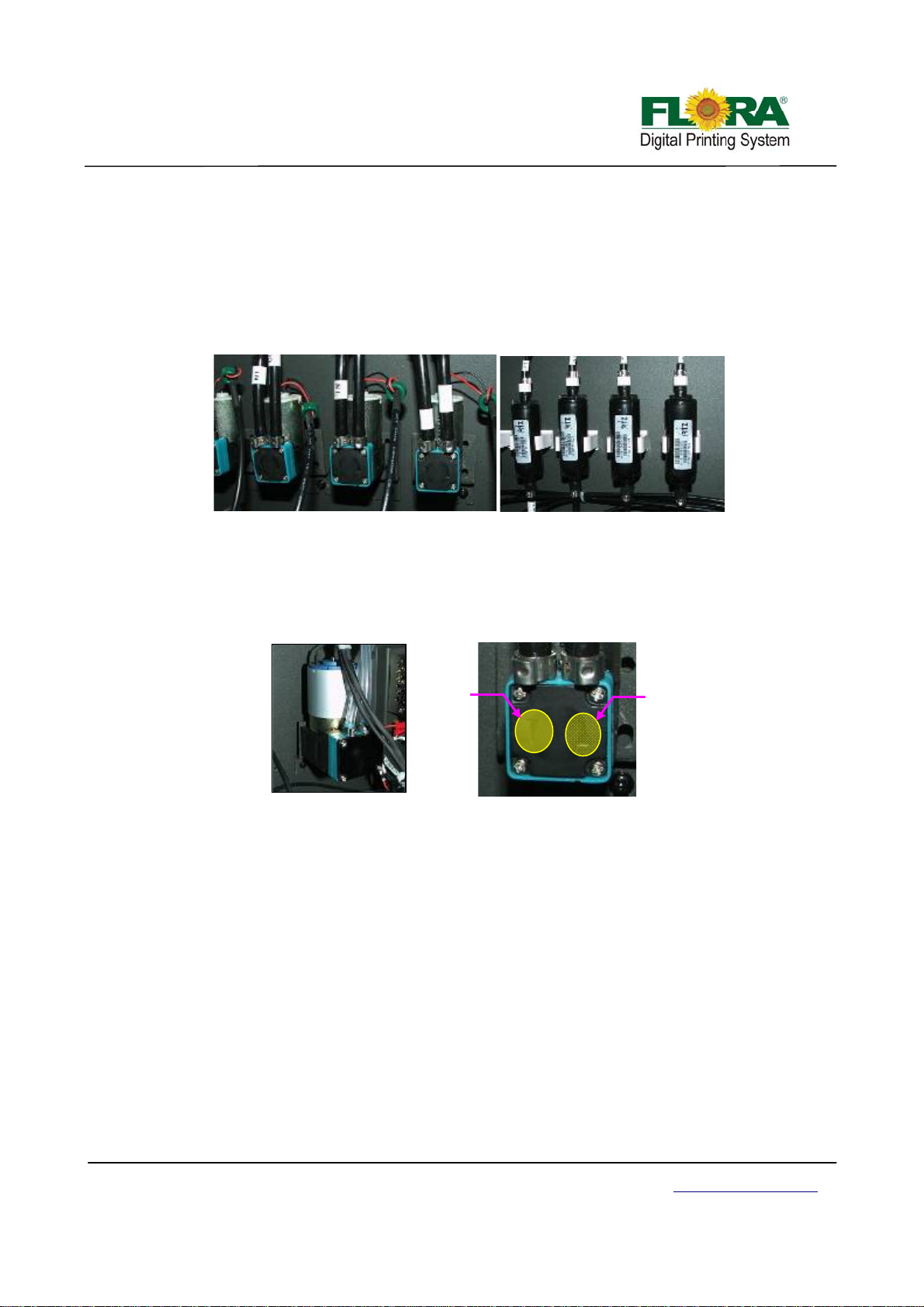
sensor will energize the LED on the Print head Control Board when the secondary ink tank is full.
If the LED doesn’t light after 2 minutes of pumping, then most likely the pump is defective or
there’s a leak somewhere along the input line. Please take note of the polarity of the power supply
cable for the ink pump, usually the red wire is connected to positive “+” while the black is to
negative “-“.
Change the ink and solvent filters every three months or approximately 800 operational
hours to ensure continuous ink and solvent flow into the system.
Ink Pumps
Ink Filters
7.3.2 Changing Defective Air Pump
If the time for the ink to reach the secondary ink tank is longer than 2 minutes, the pump
might be defective or it might be a leaking problem. When changing the Ink Pump, take note of the
polarity of the power supply cable and the direction of the arrow head for tubing connection s.
Air Pump
Suction
Discharged
Arrow head
Likewise, when the ink priming pressure becomes weak and the negative pressure will go
down below -2.0 reading, the air pump is defective or there might be some leakage somewhere in
the vacuum line system or the 4/2 way valve is malfunctioning. Usually, the vacuum pump can
attain 20-30KPa pressure when you do ink priming. When changing the vacuum pump, you must
take note of the power supply cable and flow direction of air is determined by the arrow head on
the pump.
7.4 Maintenance of Printer Moving Parts
Clean and lubricate all moving parts on a weekly basis. Apply enough light duty grease or oil
whichever is applicable in the contact surfaces. Excessive grease will help accum ulate more dirt and
might cause some untimely stoppage of some moving parts.
While excessive oil specially carriage rails and slider bearin g might drip on the printed image or
unprinted surfaces and will affect printing quality or ink adhesion on the media. It might be a safety risk if
it will fall on the floor.
7.4.1 Maintenance of X-axis
Beam X-axis guide rails and slider bearing should be clean and applied with enough light
Victor Xu Page 65 12 Jan. 2011
Copyright 2011 © Shenzhen Runtianzhi Image Technology, Co., Ltd.
http://www.floradigital.com
Page 66

r
duty grease on contact surfaces. Raster strip shoul d be clean with IPA moisten clean cloth. Both
should be done weekly.
Guide
Rails
Guide Rail and Raster Strip
tension.
the beam. The X-axis servomotor timing belt and print head wiping mechanism tension and can be
adjusted by loosening their respective mounting brackets.
Adjust
tension
here
Raster Strip
Carriage
Timing Belt
Slider
bearing
Guide Rail
Slider
bearing
Guide Rail
Carriage Left Slider bearing
Timing belts should be check monthly for traces of damages, misalignment and loose
Carriage timing belt tension can be adjusted thru two bolt tension adjuster at the left end of
Gear Pulley
Carriage Timing Belt
Rubber
Bumper
Carriage Timing Belt Tension Adjuster
X-axis Servomotor
Carriage Right Slider bearing
Adjust tension
here
Timing Belt
Servomoto
7.4.2 Maintenance of Y-axis
Beam Worm gears, support shifter, worm gear center support, guide rails and slider bearing
should be clean and applied with enough light duty grease on contact surfaces. Should be done
weekly.
Guide Rail
Worm
gear
Worm gear
Slider
Bearing
Guide
Rail
Worm Gear and Guide Rail
Victor Xu Page 66 12 Jan. 2011
Copyright 2011 © Shenzhen Runtianzhi Image Technology, Co., Ltd.
http://www.floradigital.com
Page 67
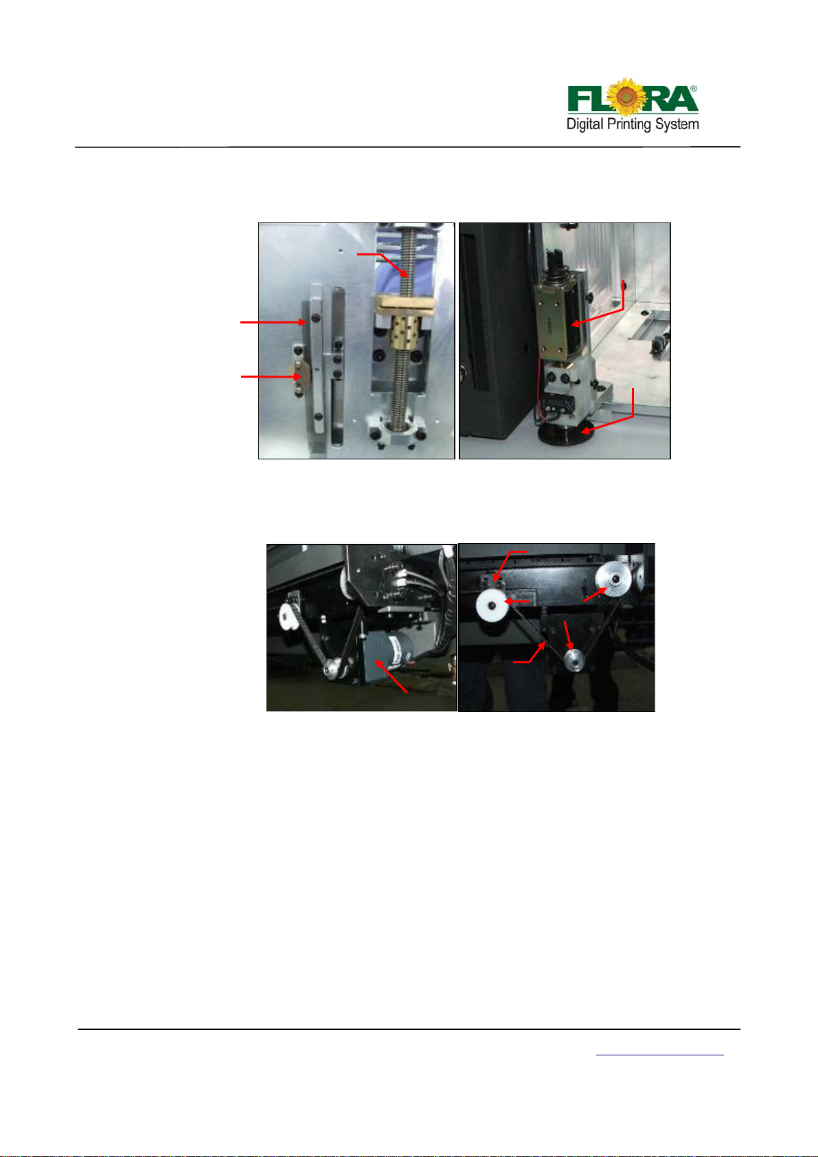
7.4.3 Maintenance of Z-axis
Media Height Auto Adjustment System should be clean and lubricate applicable parts weekly.
Worm Gear
Assembly
200DPI
Raster Strip
200DPI
Raster
Reader
Media Height
Sensor
Media Height
Sensor
Media Height Adjustment System
Media Height Sensor Assembly
7.4.4 Maintenance of auto-clean system
Print head Wiping System should be clean and lubricate applicable part weekly.
Timing Belt
Tension adjuster
Belt Gear
Pulley
Timing
Belt
Servomotor
Printhead Wiping System
Victor Xu Page 67 12 Jan. 2011
Copyright 2011 © Shenzhen Runtianzhi Image Technology, Co., Ltd.
http://www.floradigital.com
Page 68

Chapter 8 - Appendices
Appendix A Material Safety Data Sheet for UV Inks
SECTION 1: Chemical Product And Company Identification
PRODUCT NAME: VUV-Yellow/Magenta/Cyan /Black/LightMagenta/LightCyan
PART NO: VUV-Y /VUV-M/VUV-C/VUV-K/VUV-LM/VUV-LC
SUPPLIER: SHINY COLOR INKS INC.
AGENT: XUKE Advertising Equipment Inc.
Shenzhen, Guangdong China
TEL NO: 0086-755-84150772
FAX NO: 0086-755-84150773
SECTION 2: Composition/ Information of Ingredients
INGREDIENT NAME CAS NO CONTENTS HEALTH RISK
Organic Pigment 2.0-6.0 %
Ester Resin 0.1-5.0 %
Vinyl Resin 1.0-8.0 %
Cyclohexanone 108-94-1 1.0-5.0 % Xn 36
2-Butoxethyl acetate 112-07-2 60-80 % Xi 20/21
DE-Acetate 112-15-2 10-20 % Xi 37/41
N-Methyl Pyrolidinone 872-50-4 1.0-5.0 % Xn 36
SECTION 3 Hazard Identificatiion
HEALTH: Harmful if inhaled or adsorbed through skin and irritating to eyes
FIRE: Product is not classified as flammable.
SECTION 4 First Aid Measures
GENERAL ADVICE: Please call hospital emergency in case of any accident that is not instructed how to
handle
INHALA TION: Take the victim to the place for fresh air at once
INGESTION: Call hospital emergency
SKIN: Wash skin with clean water immediately
EYES: Make sure to remove any contact lenses from the eyes before rinsing. Rinse at least 15
minutes. Call hospital emergency if still feel uncomfortable
SECTION 5 Fire Safeties
EXTINGUISHER: Use Foam, Carbon dioxide (CO2) Powder.
PROTECTION EQUIPMENT: Wear mask and safety glasses
SECTION 6 Handling ink spillage
PERSONAL SAFETY: Use protective gloves and mask; avoid contact with skin or eyes.
SPILL CLEANUP METHODS: Apply toilet paper
ENVIRONMENTAL PRECAUTION: Avo id pouring waste ink into tap water drainer and soil.
Victor Xu Page 68 12 Jan. 2011
Copyright 2011 © Shenzhen Runtianzhi Image Technology, Co., Ltd.
http://www.floradigital.com
Page 69

SECTION 7 Handling and Storing
USAGE PRECAUTIONS:
Keep container sealed.
Provide good ventilation.
Avoid spilling, skin and eye contact.
Avoid inhalation of vapors.
STORAGE PRECAUTIONS
• Keep in cool, dry, ventilated storage and sealed containers.
• Protect from light, including direct sunrays.
• Keep away from heat and flame.
• Store away from oxidizing material, alkalis, acidic.
SECTION 8 Exposure Controls and Personal Protection
INGREDIENT NAME
(8 hrs) (15min)
Cyclohexanone 108-94-1 25ppm NE
2-Butoxethylacetate 112-072 25ppm NE
DE -Acetate 112-15-2 25ppm NE
N-Methyl Pyrrolidone 872-50-4 NE NE
INGREDIENT COMMENTS:
OES = Occupational Exposure Standard.
PROTECTIVE EQUIPMENT:
CAS No STD LT EXP ST EXP
PROCESS CONTROL MEASURES: Use engineering controls to reduce air contamination to permissible
exposure level. Provide eyewash station.
VENTILATION: Provide adequate general and local exhaust vent ilation.
PROTECTIVE GLOVES: Use suitable protective gloves to reduce risk of skin contact.
EYE PROTECTION: Use approved safety glasses or mask.
OTHER PROTECTION: Wear suitable p rotective cloth for protection against splashing or contamination.
HYGIENIC WORK HABITS: Wash hands at the end of each work shift, before eating, smoking and using the
toilet.
Change cloth that becomes wet. Isolate contaminated cloth and wash befo re
reuse. Use appropriate hand lotion to prevent aging and cracking of skin. No
eating or drinking while working with this material.
SECTION 9 Physical and Chemical Properties
Existing form: Liquid
Color: Yellow/Magenta/Cyan/Black
Boiling degree: 191
Flash degree: 88
Auto ignition Temperature: no data
Flammability limits (vol %): no data
Victor Xu Page 69 12 Jan. 2011
Copyright 2011 © Shenzhen Runtianzhi Image Technology, Co., Ltd.
http://www.floradigital.com
Page 70

Relative density (g/cm3,25): not determined
Solubility in water (g/l,20): not soluble
SECTION 10: Stability and Reactivity
Stability: Stable under normal conditions in tightly closed container decomposition if used according to
specifications.
Materials to Avoid: Avoid contact with oxidizing materials, strong acids, strong bases, air or oxyge n.
Hazardous Polymerization: Not relevant.
Conditions to Avoid: Avoid sources of ignition
SECTION 11: Toxicological Information
INHALATION: Gas or vapor in high concentrations may irritate respiratory system.
SKIN CONTACT: Acts as a defeating agent on skin may cause cracking of skin.
EYES CONTACT: Primary irritant effect may cause severe irritation to eyes.
INGESTION: Low acute oral toxicity.
SECTION 12: Environmental Information
MOBILTY: Partly miscible with water.
BIO ACCUMULATION: Bio accumulation unlikely.
DEGRADABILITY: Readily biodegradable. Do not allow product to reach ground water course or
seawage system.
SECTION 13: Disposal Considerations
GENERAL/CLEANING:
Refer to Section 7 before handing the product or containers.
DISPOSAL METHODS:
Disposal must be in accordance with current national and local regulations. Chemical residues generally
count as special waste.
SECTION 14: Transport Information
GENERAL: Not regulated.
LABEL FOR CONVEYANCE: No transport warning sign required.
ROAD:
HAZARD CLASS (ADR): Not classified for transportation. The product is not subject to transport
regulations of Rail, Sea, Air.
SECTION 15: Regulatory Information
LABEL FOR SUPPLY:
DANGER SYMBOL:
Xn (Harmful)
RISK SYMBOL:
R-36: lrritating to eyes.
R-21: Harmful by inhalation
R-20: Harmful in contact with skin
SAFETY PHRASES:
S-25 Avoid contact with eyes.
Victor Xu Page 70 12 Jan. 2011
Copyright 2011 © Shenzhen Runtianzhi Image Technology, Co., Ltd.
http://www.floradigital.com
Page 71

S-26 In case of contact with eyes, rinse immediately with plenty of water and seek medical advice.
S-28 After contact with skin, wash immediatel y with plenty of water.
S-36/37/38 Wear suitable protective cloth and gloves and eye/face prote ction
S-60 This material and its container must be disposed of as hazardous waste.
SECTION 16 Other Information
This data sheet is prepared in accordance with directive. The information on this sheet is intended to
provide general guidance to health and safety based upon our knowledge of the handling, storing and using
of our products. It is not applicable to other products.
Victor Xu Page 71 12 Jan. 2011
Copyright 2011 © Shenzhen Runtianzhi Image Technology, Co., Ltd.
http://www.floradigital.com
Page 72
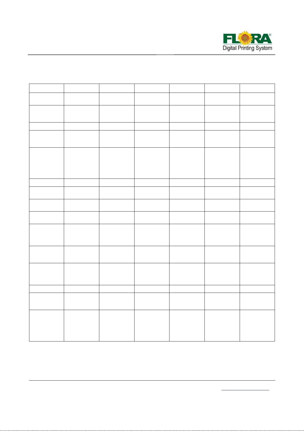
Appendix B Preventive Maintenance Checklist
Item Daily Weekly Monthly Quarterly Semi-annual Annual
Ink Supply Level Check and shake
Waste Ink Bottle Check for level,
Ink Filters Change
Ink Pumps Check and
UV Lamps Check and
UV Lamp Filters Check and Clean
Flat Bed
Conveyor
Carriage Linear
Guide Rail
Carriage Bearing Check, Clean
Carriage Belt Check the
Y-feed conveyor
drive gear head
oil
Vacuum Cleaner
and Filter Bag
Cleaning Station Check and Clean
Raster
Strip/Ruler
Automatic
Carriage Height
mechanism
Note: 500 Hrs after installation, the Y-feed conveyor drive gear head oil should be changed.
on startup
dispose if full or
nearly full
Clean
Check, Clean
Oil change Oil Change
Check for waste
Wipe with lint free
cloth before
startup
Check if spring is
functional (The
plunger should
return at
up/home
position)
replace if
necessary
change if
necessary, left
UV lamp and
right UV lamp at
the same time
and Lubricate
and Lubricate
Change Filter
ink level and
Clean if
necessary
tension, adjust
tension if
necessary
Bag
Victor Xu Page 72 12 Jan. 2011
Copyright 2011 © Shenzhen Runtianzhi Image Technology, Co., Ltd.
http://www.floradigital.com
Page 73

•
Appendix C Troubleshooting Guide
Problems Probable Causes Solution
o No ink flowing to the tube line
of the Print head Carriage
o Empty ink supply in the Ink
barrel
One particular
color is not
printing
1. Some Print head
Nozzles are not
firing
2. Print head firing
is not straight
Ink Starvation
Cannot achieve
correct negative
pressure
Negative
pressure keeps
on changing from
time to time
Air Pump is not
working
Ink Pumps are
not working
All Ink Pumps
are not working
o Clogged Ink line tubing and
ink filter
o Defective Ink Pump
o Defective Print head Control
Board
o Defective Motion Control
Board
o Air bubbles on the ink tube
Clogged Print head
Print head problems
Defective Print head Cable
Defective Print head Control
Board
o Insufficient Negative
Pressure value
o Print head nozzles are not
working well
o Insufficient ink flowing from
the Disc Filter to the Print
head because of clogged
disk filter
o Presence of ink in the Ink
Protect Tank
o Defective Negative Pressure
Regulator
o Defective Pressure Gauge
o Defective Air Pump
o Possible leak in the vacuum
line system (negative
pressure line)
o Presence of ink in the Ink
Protect Tank
o Ink Tank Sensor might not be
working that is why ink is
overflowing to the Ink Protect
Tank
o Presence of ink in the Ink
Protect Tank
o Defective / Out of Position
Ink Protect Level Sensor
1. Fill-up empty ink barrel
2. Replace clogged ink line tubing and ink
filter
3. Replace defective Ink Pump
4. Replace defective Print head Control
Board
5. Replace defective Motion Control Board
6. Purge air from the affected ink tube.
Perform Ink Priming
• Replace defective Print head
• Replace defective Print head Cable
• Replace defective Print head Control
Board
• Adjust the Print head Voltage
Increase the Negative Pressure value
from
-2.2KPa to -2.6KPa
Perform Test Print to check if all the Print
head nozzles are working well, flush and
ink prime as needed
Replace Filter
Remove or purge any presence of ink in
the Ink Protect Tank
Replace defective Negative Pressure
Regulator
Replace Pressure Gauge
Replace Air Pump
Fix any air leak from the vacuum line
system.
Replace Air Fittings if necessary
Fix/replace the Ink Tank Sensor
Remove the ink from the Ink Protect Tank
using the Syringe from the Ink Outlet
Tube vent
Remove or purge any presence of ink in
the Ink Protect Tank
Replace/Fix Ink Protect Level Sensor by
opening the Ink Protect Tank
Victor Xu Page 73 12 Jan. 2011
Copyright 2011 © Shenzhen Runtianzhi Image Technology, Co., Ltd.
http://www.floradigital.com
Page 74

No Print at all
No presence of
Printhead
Volt age from
RTZ software
Carriage gets in
contact with
media during
printing
Carriage is not
moving, left to
right stroke
Media is not
moving,
backward and
forward stroke
Ink is not drying
Horizontal
banding
A particular
portion of the
printer is
showing
horizontal
banding
o The Optical Cable must have
been interchanged during
installation
o Gap between carriage and
media (printing platform) is
too close.
o Media suction is not working
o Wrinkled / curled media
o Defective AC Servo Motor
o Corrupted/Defective Servo
Driver
o Worn-out Timing Belt
o Defective Motion Control
Board
o Defective DC Servo Motor
o Defective Movement Control
Board
o Worn-out Timing Belt
o Defective Motion Control
Board
o Heat is not enough to dry the
ink
o Heater is not working
o Heater controller is not
working
o Density or the ink limits of
the image setup is too high
o Clogged Print head
o Step alignment is not good
o Print head alignment is not
good
o Feeding of the Pinch Roller
is not equal
Interchanged again the Rx/Tx connection
of the Optical Cable either from the PCI
card or in the Printhead Control Board
Adjust the Printer Carriage between 2.0 –
2.5mm.
Check the 24V supply of suction fans,
replace defective suction fan if necessary
Replace the media to avoid wrinkled
media to be in contact with the print head
during printing
Replace defective Servo Motor
Re-program the Servo Driver, replace if
defective
Replace worn-out Timing Belt
Replace Motion Control Board
Replace defective DC Servo Motor
Replace worn-out Timing Belt
Replace Movement Control Board\
Replace Motion Control Board
Increase the heater’s temperature from
the printing platform as well as the front
heater
Replace defective heater
Replace heater controller
Lower the ink limits of the image profile
Decrease the Ink limits of the image
Perform solvent flushing and Ink Priming
(make a
longer flushing if needed) then check
us of the Print head in Test Print.
Adjust the motor step s (see Print head
nment
Procedure)
Aligned the Print head very well (se e Print
head Alignment Procedure)
Adjust the tension of the Pinch Rolle r
(see Pinch Roller Adjustment Procedure)
Victor Xu Page 74 12 Jan. 2011
Copyright 2011 © Shenzhen Runtianzhi Image Technology, Co., Ltd.
http://www.floradigital.com
Page 75

Inconsistent step
align problem
Vertical Banding
on the right side
portion of the
machine
Carriage
suddenly stops
during operation
X-alignment
problem during
printing
Portion of the
RIPed image
was not printed
Output size of
the image print is
not same with
the defined
image dimension
o Feeding of the Pinch Roller
is not equal
o Worn-out Gear Box
Assembly
o Defective Motor Encoder
o Worn-out Timing Belt
o Raster Strip might have
scratches on that portion
o Loose connection on the
Print head Cable Data lines
o Tension on energy chain
assembly
o Raster Strip is too dirty
o Portion of Raster Strip has
severe scratches
o Defective Raster Strip
o Defective Raster Encoder
o Raster Encoder is not
properly setup with raster
strip
o The RIPed image dimension
is almost /more than
2000in/50m.
o The RIPed image file is more
than 4G bytes
o Tension Roller problem
o Needs to perform Output
Size Compensation
Adjust the tension of the Pinch Roller (see
Pinch Roller
Adjustment Procedure)
Replace worn-out Red ucer Gear Box
Replace Y-Axis Servo Motor
Replace Timing Belt
Replace the Raster Strip
Fix loosed Print head Cable Data lines
Fix/replace the energy chain
Re-setup and cabling on the energy
chain
Clean Raster S t rip .
Replace defective Raster Strip
Replace defective Raster Encoder
Perform Raster Alignment
Reduce the size to be RIPed to
manageable size to avoid RIPing error
Adjust/setup the roller tension properly
See page 48 for proper procedure in
using Output Size Compensation
Victor Xu Page 75 12 Jan. 2011
Copyright 2011 © Shenzhen Runtianzhi Image Technology, Co., Ltd.
http://www.floradigital.com
Page 76

Appendix D Glossary
Adobe Acrobat - Software package created by Adobe for converting any document to an Adobe Portable
Document Format (PDF) file. Anyone can open your document across a broad range of hardware
and software using the downloadable, free software Adobe Acrobat Reader, and it will look exactly as you
intended—with layout, fonts, links, and images intact.
Aliasing - A defect which occurs when a graphic file does not have enough resolution to reproduce image
detail and causes visible jagged lines along the edges
Attachment - When referring to e-mail, an electronic file placed within an e-mail for the purpose of sending
through the Internet.
Banding - It is the horizontal, parallel lines in an ink jet print caused by a falsely aligned or defective print
head. It is also the vertical lines caused by some mechanical problem.
Bi-directional Printing - Printing in which the print head alternates printing a line left to right, then the next
line right to left, etc.
Bitmap Images - Computerized image made up of a collection of dots or pixels; these images appear
blocky when you zoom in; also known as raster images
Bleed - Ink which prints beyond the trim edge of the page, created for the purpose of allowing ink to extend
to the edge of the page after trimming. Without bleed, cutting the product becomes extremely difficult and
may sacrifice the quality of the product.
CMYK - cyan, yellow, magenta, black. The subtractive primaries or process colors, used in color printing.
Black (K) is usually added to enhance color and to print a true black.
Color Bar - Strips of color used as a tool to check color accuracy and density
Color Mapping - The terminology that permits the “be st match ” in appearance to the “source image”.
Color Separations - The process of preparing artwork, photographs, transparencies, or computer-gen era ted
art for printing by separating color into the four primary printing colors: cyan, magent a, yellow and black.
Contrast: The comparing of light and dark on an image, such as low = gray (light).
Crop - To cut off parts of a picture or image.
Crop marks - Printed lines showing where to trim a printed sheet.
Densitometer - A quality control device used to measure the density of printing ink.
Density - The degree of color or darkness of an image or photograph.
DCM Driver Chip Module - Part of Spectra 96 chip print head. Consists of a printed circuit board with driver
chips, attached to a lead frame of sprung legs that are pushed into contact with pads on the PZT.
Dithering: Creating dots to “fool the eye” into seeing shades of gray.
Victor Xu Page 76 12 Jan. 2011
Copyright 2011 © Shenzhen Runtianzhi Image Technology, Co., Ltd.
http://www.floradigital.com
Page 77

Dot Size - Relative size of halftone dots as compared to dots of the screen ruling being used. There is no
unit of measurement to express dot size. Dots are too large, too small or correct only in comparison to what
the viewer finds attractive.
Dots-per-inch - Measure of resolution of input devices such as scanners, display devices such as monitors,
and output devices such as laser printers, image setters and monitors. Abbreviated DPI. Also called dot pitch.
Drop-On-Demand (DOD) / impulse - an ink jet system in which pressure pulses are generated directly in
the print head by piezo crystals or heated resistors to eject drops of ink only when they are needed to print a
dot
Drop Mass or Drop Volume - The size of a jetted drop of ink, usually measured in nanograms. Adequate
jet-to-jet drop mass uniformity is required in many applications to eliminate banding When the specific gravity
is 1, 1picoliter (pL) = 1 nanogram (ng).
Drop Velocity - The speed at which a drop of jetting fluid travels from the orifice plate to the receiving
medium.
Encapsulated Postscript File (EPS) - An Adobe graphic file format for high resolution images; it translates
graphic and text into code that tells a printer to print in the highest resolution possible and also has low
resolution view files for quick screen viewing.
Encoder - An encoder is a device or transducer that converts linear or rotary motion information into
uniformly spaced incremental signals.
First In First Out (FIFO) - A form of low-level memory (for example, a shift register. Used in the data path for
temporary storage of bitmap data on its way to a print head.
Fire Pulse - A high voltage electrical signal of precise shape, amplitude, and width, causing a jet to eject a
drop. Also cal led a drive pulse.
Firmware - Embedded software, i.e., software that is not loaded from a storage device at startup, but instead
resides on the board or in the chip.
Fire Pulse Amplitude (FPA) - The peak voltage of a fire pulse.
File Transfer Protocol (FTP) - The language used to facilitate the transfer of files from a server on the
Internet to another location, such as a desktop computer or another server.
GIF Graphic Interchange Format - An image format type generated specifically for computer use. Its
resolution is usually very low (72 dpi, or that of your computer screen), making it undesirable for printing
purposes.
Gradient - Color in shades from one starting point to another gradually blending in between. A grade change
in a hue. It is a transition of color, creating a blended change between screen percentages of a single color
or between two different colors
Grain - The direction in which the paper fiber lie.
Head Drive Electronics Module (HDEM) - This is the component of the Apollo PSK that creates the high
voltage drive pulses. It is programmable for pulse amplitude and width, as well as rise and fall time.
Victor Xu Page 77 12 Jan. 2011
Copyright 2011 © Shenzhen Runtianzhi Image Technology, Co., Ltd.
http://www.floradigital.com
Page 78

Hypertext Markup Language (HTML) - A series of formatting commands that describes the components of
graphics and text material presented on the World Wide Web in a consistent manner
Image Area - Portion of paper on which ink can appear.
Image - Usually a photograph that is “translated into a bitmapped” image by scanning Ink Jet Printing
Method of printing by spraying droplets of ink through computer-controlled nozzles. Also called jet printing.
Initialization File - A file, usually with the extension .INI, that sets startup variables for an application
program.
Large Format Printing - refers to large sized prints, typically A1 sized or larger, produced in full color
utilizing full color digital ink jet printers.
Materials Safety Data Sheet (MSDS) - This is a document which describes the potential safety hazards of a
chemical, liquid or solid, and instructs how to handle it safely and h ow to respond to exposures or spills.
Meniscus - The curved surface at the top of the water column, or at any interface between a liquid and a
solid. Nozzles have a meniscus, whose shape and position are set by a slight negative pressure in the jets at
rest, balanced against the surface tension of the liquid.
Meniscus Pressure Used at Spectra - the meniscus pressure often refers to an inward bubble pressure
that equals the fluid pressure at a print head jet nozzle when that jet is not activated. A negative meniscus
pressure is applied to inactivated jets only when the print head system is operating, helping to prevent the
jetting fluid from leaking at the nozzles. More generally, meniscus pressure is the negative pressure created
behind a meniscus, due to surface tension.
Portable Document Format (PDF) - An electronic document format from Adobe that allows the distribution
of digital files across any platform that can display a document as originally designed and formatted without
having the software application or fonts on the viewing comp uter.
Pigment - Particles that absorb and reflect light and appear colored to our eyes; the substance that gives ink
its color.
Pixel - A single dot on a monitor or on digital image.
Print head - part of a digital printer that is directly responsible for applying in k to a substrate
Protocol - The set of conventions defining communication between electronic components, for example, and
a host computer and its interface. The way information is placed on a network. The steps needed to
communicate or activate an operation or exchange of information in or between computers.
Purge - Performed for a variety of print head maintenance reasons, a purge is a regulated pressure applied
for a fixed amount of time at the air interface to the ink reservoir attached to the print head jetting assembly
to force ink, along with air bubbles and debris if present, out the jets through the nozzles.
Raster - A line of pixels. Also the process of rendering an image or page, pixel by pixel, in a sweeping
horizontal motion, one line after another.
Rasterization - The process of converting mathematical and digital information (vector commands) into a
series of dots by an output device.
Victor Xu Page 78 12 Jan. 2011
Copyright 2011 © Shenzhen Runtianzhi Image Technology, Co., Ltd.
http://www.floradigital.com
Page 79

Raster Image Processor (RIP) - A combination of computer software and hardware that controls the printi ng
process by calculating the bit maps of images and instructs the printing device to create the images. Most
RIPs operate on PostScript.
Resolution - The DPI or dots per inch of a design. Measured by how many dots or pixels are in one inch of a
design. The measurement of the fineness or detail. The higher the resolution the finer the detail in an image
Satellites - Small droplets of jetting fluid generated behind the main drop as the main drop detaches from
the nozzle.
Substrate - Any surface on which printing is done.
Tagged Image File Format (TIFF) - A standard graphic image file format often used for storing high
resolution images that can easily handle up to 24 bits of photographic image color.
Transmission Control Protocol/Internet Protocol (TCP/IP) - is an open communications protocol
implemented on diverse systems and the Internet and is the preferred protocol for practical in teroperability.
Varnish - A clear liquid coating applied to printed sheet for protection and glossiness.
Varnishing - a finishing process whereby a transparent varnish is applied over the printed sheet to produce
glossy finish.
Viscosity - the tendency of a liquid to flow slowly or quickly resulting from the friction of its molecules
Victor Xu Page 79 12 Jan. 2011
Copyright 2011 © Shenzhen Runtianzhi Image Technology, Co., Ltd.
http://www.floradigital.com
 Loading...