

Page 1

ruby 45e
ruby 50e
ruby 55e
01 2007
Use and maintenance
Attention! Please read the instructions before use.
COD. 65305002
Page 2

GB GB
13
SUMMARY
LEGEND INSTRUMENT BOARD AND CONTROLS 14
LEGEND MACHINE 14
OPTIONAL ACCESSORIES 15
TECHNICAL DESCRIPTION 15
INTRODUCTORY COMMENT 16
GENERAL RULES OF SECURITY 16
SYMBOLOGY 16
BEFORE USE 17
Handling of the packed machine 17
Unpacking of the machine 17
Squeegee assembly 17
Adjustment of the squeegee height 17
Adjustment of the squeegee inclination 17
Splash guard assembly 17
Manual assembly of the brushes 17
Automatic brush assembly (ruby50e) 18
Recovery tank 18
Detergent solution tank 18
FLOOR CLEANING 18
Starting of the machine 18
Adjustment of the brushes pressure (optional) 18
Brushes motor overload protection device 18
Overflow device 18
Emptying detergent solution 19
Emptying device detergent solution (optional) 19
Forward movement 19
Stop 19
Adjustment of brushes inclination (optional ruby45e, ruby55e) 19
STOP OF THE MACHINE AFTER CLEANING OPERATION 19
DAILY MAINTENANCE 19
Recovery tank cleaning 19
Suction filter cleaning 19
Brushes cleaning 19
Brushes disassembly (ruby45e, ruby55e) 20
Automatic brush disassembly (ruby50e) 20
Squeegee cleaning 20
WEEKLY MAINTENANCE 20
Rear squeegee rubber replacement 20
Squeegee hose cleaning 20
Cleaning of solution tank and filter 20
TWO-MONTHLY MAINTENANCE 20
Front squeegee rubber replacement 20
SIX-MONTHLY MAINTENANCE 21
Splash guard replacement 21
TROUBLESHOOTING GUIDE 21
The suction motor does not work 21
The brushes motor does not work 21
Insufficient water on the brushes 21
The machine does not clean properly 21
The squeegee does not dry perfectly 21
Excessive foam production 21
PROGRAMMED MAINTENANCE 22
RECOMMENDED BRUSHES 22
Page 3
GB GB
14
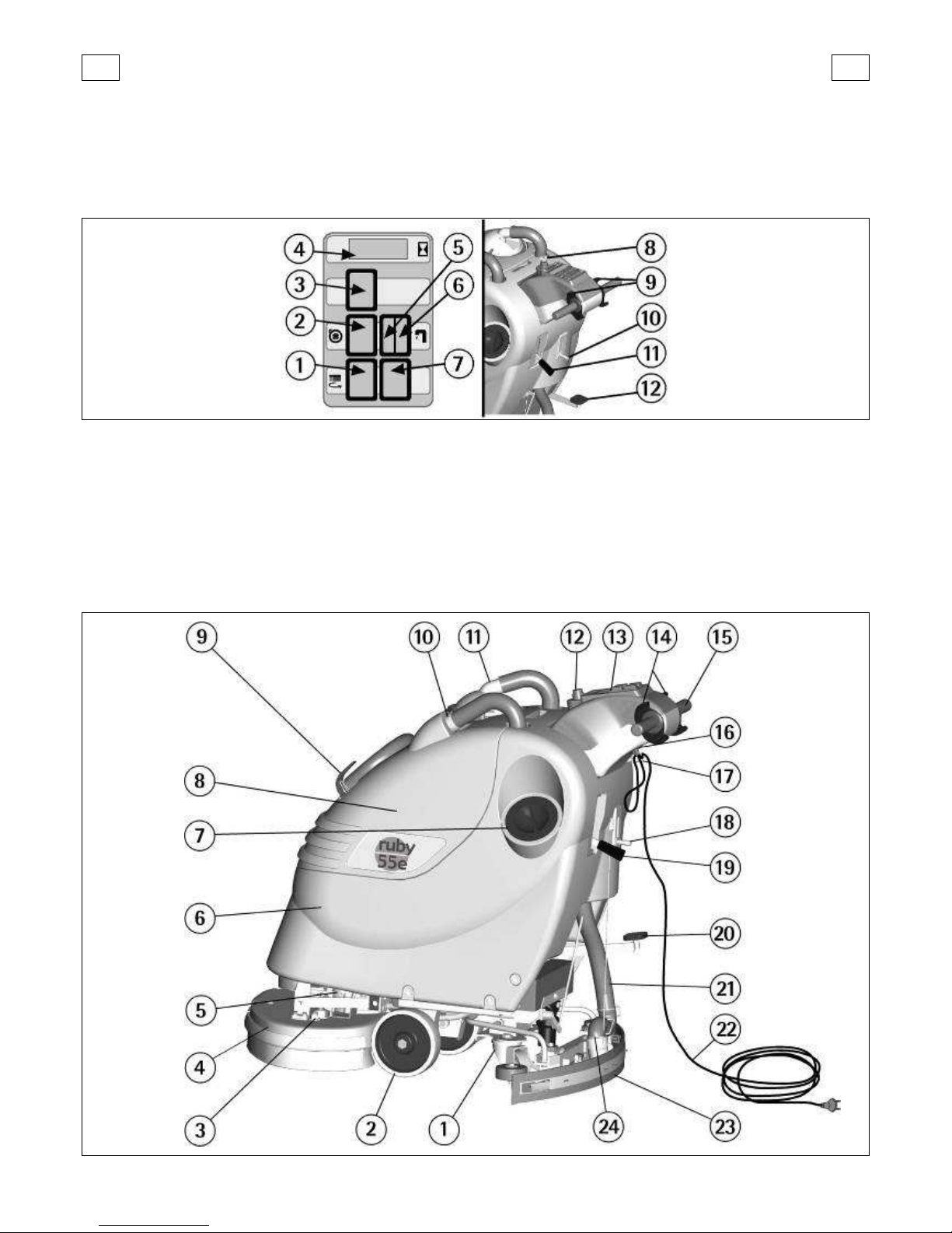
LEGEND INSTRUMENT BOARD AND CONTROLS
1. SWITCH BRUSHES MOTOR
2. SWITCH SUCTION MOTOR
3. PUSH BUTTON BRUSH RELEASE (only on ruby 50e)
4. HOUR METER (OPTIONAL)
5. SIGNAL LAMP FOR PRESENCE OF THE TENSION
6. SIGNAL LAMP SOLENOID VALVE ON (OPTIONAL)
7. RESTORABLE FUSE BRUSHES MOTOR
8. SWITCH WITH KEY (OPTIONAL)
9. LEVERS FOR PRESENCE
10. LEVER SOLUTION VALVE
11. LEVER SQUEEGEE LIFTING
12. PEDAL BRUSHES BASE GROUP LIFTING
LEGEND MACHINE
1. CASTOR WHEELS
2. WHEELS
3. ADJUSTMENT BRUSHES INCLINATION (OPTIONAL only on ruby45e/55e)
4. BRUSHES BASE GROUP
5. SOLENOID VALVE (OPTIONAL)
6. SOLUTION TANK
7. SCREW CAP FOR INLET DETERGENT SOLUTION
8. RECOVERY TANK
9. PLUG EXHAUST HOSE RECOVERY TANK
10. INLET OPENING SQUEEGEE HOSE
11. SUCTION COVER
12. SWITCH WITH KEY (OPTIONAL)
13. INSTRUMENT BOARD
14. LEVERS FOR PRESENCE
15. HANDLE BARS
16. MAINS PLUG FOR CABLE
17. SUPPORT CABLE BLOCK
18. LEVER SOLUTION VALVE
19. LEVER SQUEEGEE LIFTING
20. PEDAL BRUSHES BASE GROUP LIFTING
21. SQUEEGEE HOSE
22. MAINS CABLE
23. SQUEEGEE ASSEMBLY
24. GUIDE SPRING SQUEEGEE HOSE
Page 4
GB GB
15
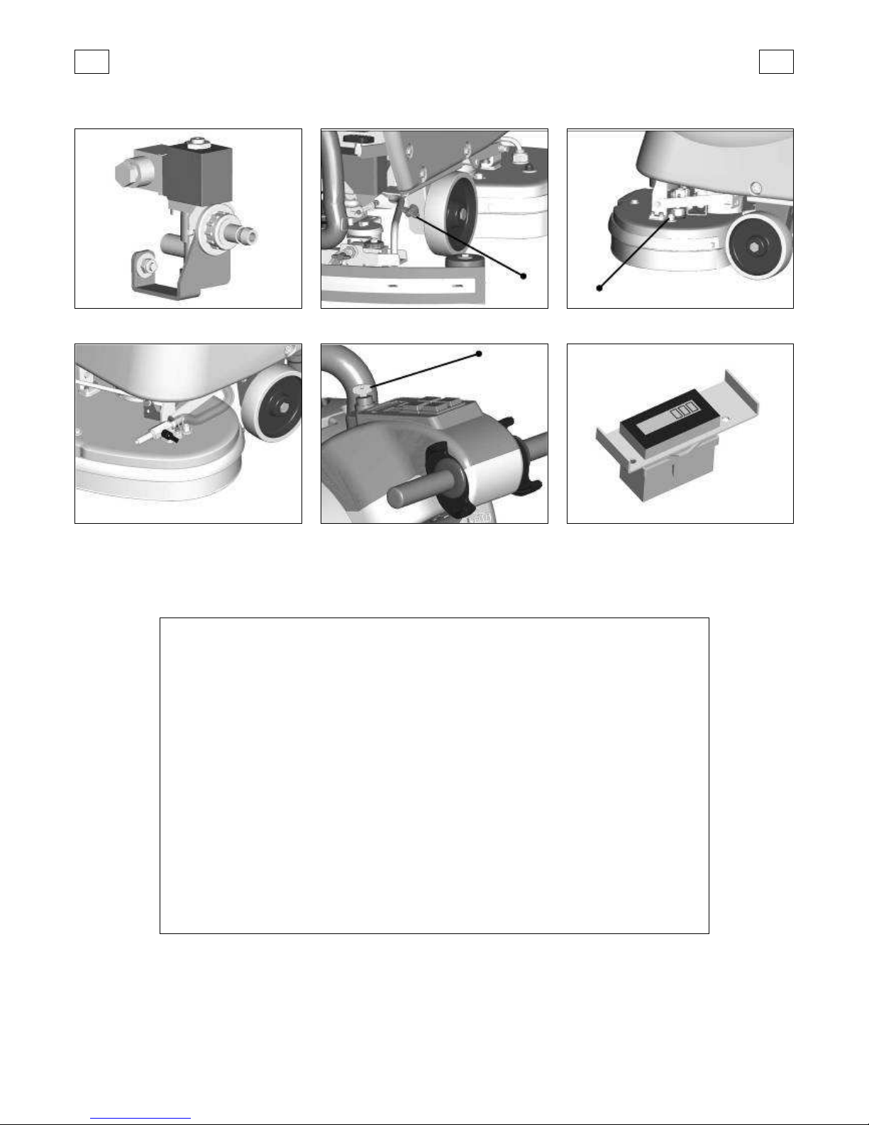
OPTIONAL ACCESSORIES
Solenoid valve
Adjustment brushes pressure
Adjustment brushes inclination (ruby45e, 55e)
Emptying device of the solution tank
Switch with key
Hour meter
TECHNICAL DESCRIPTION
U/M
ruby 45e
ruby 50e
ruby 55e
Cleaning width mm 450 500 550
Squeegee width mm 790 790 790
Working capacity, up to sqm/h 1575 1750 1925
Brushes diameter mm 2x235 1x508 2x285
Brushes rpm rpm 432 182 345
Pressure on the brushes kg 22 max 30 max 25 max
Brushes motor W 1000 1000 1000
Type of drive semi-aut. semi-aut. semi-aut.
Maximum gradient 2% 2% 2%
Suction motor W 450 450 450
Suction vacuum mbar 110 110 110
Solution tank l 45 45 45
Recovery tank l 48 48 48
Machine length mm 1102 1205 1140
Machine height mm 1033 1033 1033
Machine width (without squeegee) mm 527 535 586
Weight of the machine (empty) kg 85 89 87
Mains cable (length) m 20 20 20
Power supply V 230 230 230
Frequency rate Hz 50 50 50
Noise level dB(A) 66,3 66,2 66,3
Level of vibration m/sqs 0,45 0,50 0,45
Class I I I
Protection level IP 23 23 23
Page 5
GB GB
16
INTRODUCTORY COMMENT
Thank you for having chosen our machine. This
floor cleaning machine is used for the industrial
and civil cleaning, suitable fo r hard and not very
rough floorings. During its advance movement,
the combined action of the brushes and the detergent solution removes the dirt which is aspirated through the rear suction assembly, giving a
perfectly dry surface.
The machine must be used only for such purpose.
It gives the best performanc e if it is used correctly and maintained in perfe ct efficiency. We
therefore ask you to read this instruction booklet
carefully whenever difficulties arise in the course
of the machine’s use.
In case of need, we ask you to contact our service
department for all advice and servicing as may
prove necessary.
GENERAL RULES OF SECURITY
The rules below have to be followed carefully in
order to avoid damag es to the operator and to
the machine.
- Read the labels carefully on the machine. Do
not cover them for any reason and replace them
immediately if damaged.
- The machine must be used exclusively by authorized staff that has been instructed for its use.
- During the working of the ma chine, pay attention to other people and especially to the children.
- Do not mix different detergents, avoiding harmful odours.
- Do not place any liquid containers onto the machine.
- Storage temperature: between -25°C and +55°C.
- Perfect operating temperature: between 0°C
and 40°C.
- The humidity should be between 30 and 95%.
- Do not use the machine in explosive atmosphere.
- Do not use the machine as a me ans of t ransport.
- Do not use a cid solutions which could damage
the machine and/or the persons.
- Do not touch or pass over the mains cable while
the brushes are operating.
- The socket for the power supply must be
equipped with a standard earthing (ground) system.
- Do not damage the mains cable with squashings, bendings or stressings.
- Check the integrity of the m ains cable. If during
working a damage is notice d, stop the machine
immediately and take off the plug from the
mains socket. Replace with the special cable
available at the authorized center of the technical assistance.
- In bad mains conditions, the machine could
cause transitory voltage drops.
- Avoid working with the brushes when the machine stands still, in order to prevent floor damages.
- Do not use the machine on surfaces covered
with inflammable liquids or dusts (for example
hydrocarbons, ashes or soot).
- In case of fire, use a powder fire-extinguisher.
Do not use water.
- Do not strike shelvings or scaffoldings, where
there is danger of falling objects.
- Adapt the working speed to the adhesion conditions.
- Do not use the machine on areas having a
higher gradient than the one stated on the nu mber plate.
- The machine has to carry out simultaneously
the operations of washing and drying. Different
operations must be carried out in restricted areas
prohibited to non-authorized personnel.
- Signal the areas of moist floors with suitable
signs.
- If the machine does not work properly, check by
conducting simple maintenance procedures.
Otherwise, ask for technical advice to an authorized assistance centre.
- Where parts are required, ask for ORIGINAL
spare parts to the distributor and/or to an authorized dealer.
- Use only ORIGINAL brushes indicated in the
paragraph “RECOMMENDED BRUSHES".
- For any cleaning and/or maintenance operation
take off the power supply from the machine.
- Do not take off the protections which require
the use of tools to be removed.
- Do not wash the ma chine wi th di rect water jets
or with high water pressure nor with corrosive
material.
- Every 200 working hours have a machine check
through an authorized service department.
- In order to avoid scal es on the solution tank filter, do not fill the detergent solution many hou rs
before the machines’ use.
- Before using the machine, check that all pan els
and coverings are in their position as indicated in
this use and maintenance catalogue.
- Be sure the recovery tank is empty before removing it.
- Restore all electrical connections after any
maintenance operation.
- Provide for the scrapping of the material of
normal wear following strictly the respective
rules.
- When your machine has to stop activity, provide for the appropriate waste disposal of its materials, especially oils and electronic components,
and considering that the machine itself has been,
where possible, constructed using recyclable m aterials.
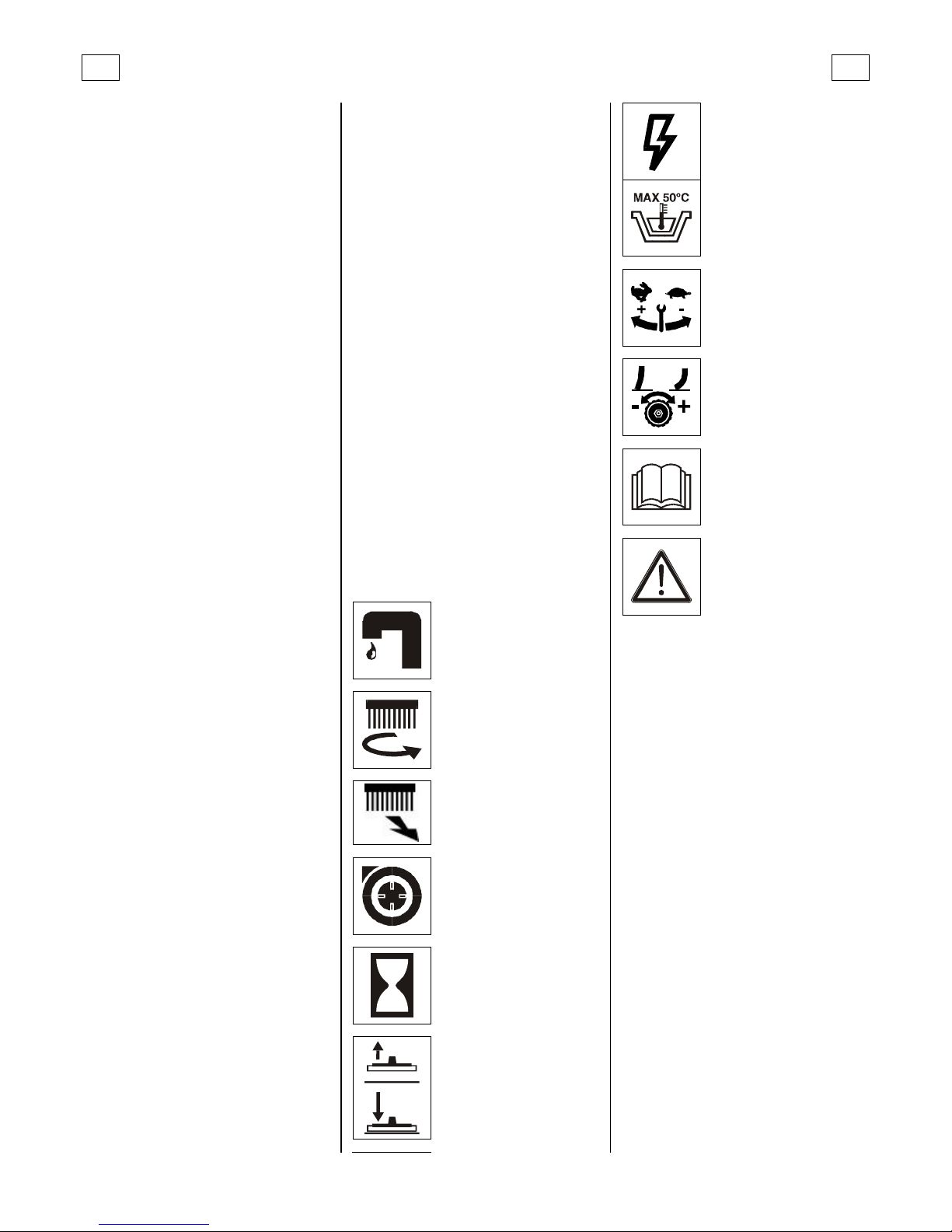
SYMBOLOGY
Symbol denoting the solution
valve.
Indicates the solution valve
lever and the signal lamp of the
solenoid valve (optional).
Symbol denoting the brush.
Indicates the switch of the
brushes motor.
Symbol denoting the brush
release. Indicates the push
button used to release the
brush automatically (only on
ruby50e).
Symbol denoting the suction
motor.
Indicates the switch of the
suction motor.
Symbol denoting the hour
meter (optional).
Symbol denoting up – down of
the squeegee.
Indicates the squeegee lever.
Symbol denoting the flash.
Indicates the signal lamp for
presence of the mains tension
on the machine.
Indication of the maximum
temperature of the solution
detergent.
It is placed near the charging
hole of the solution tank.
Symbol denoting the speed
adjustment of the traction
through the brushes
inclination (optional for
ruby45e and ruby55e).
Symbol denoting the
squeegee adjustment.
Symbol denoting the open
book.
Indicates that the operator
has to read the manual before
the use of the machine.
Warning symbol.
Read carefully the sections
marked with this symbol, for
the security of both the
operator and the machine.
Page 6
GB GB
17
BEFORE USE
HANDLING OF THE PACKED MACHINE
The machine is supplied with suitable packing
foreseen for fork lift truck handling.
The total weight is 111 kg.
Packing dimensions:
Base: 1175 mm x 665 mm
Height: 1185 mm
ATTENTION:
Do not place mo re than two packings on top of
each other.
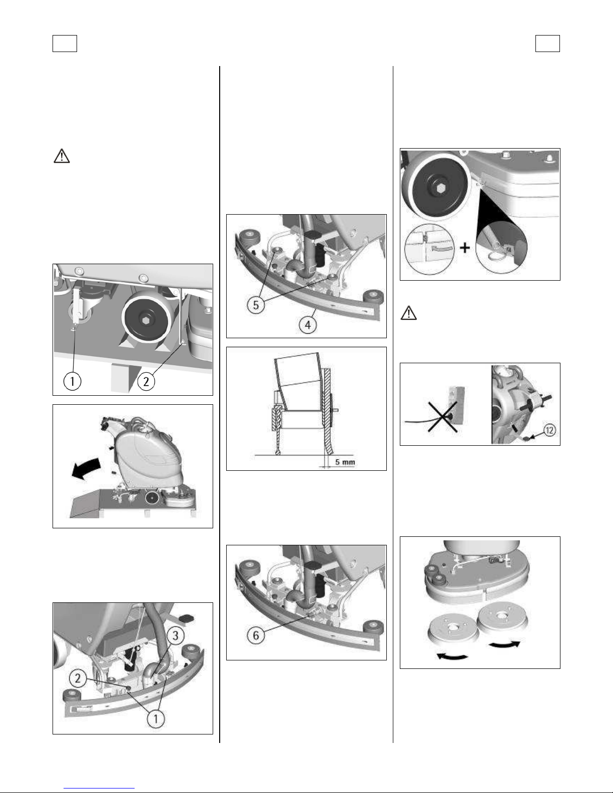
UNPACKING OF THE MACHINE
1. Remove the external packing.
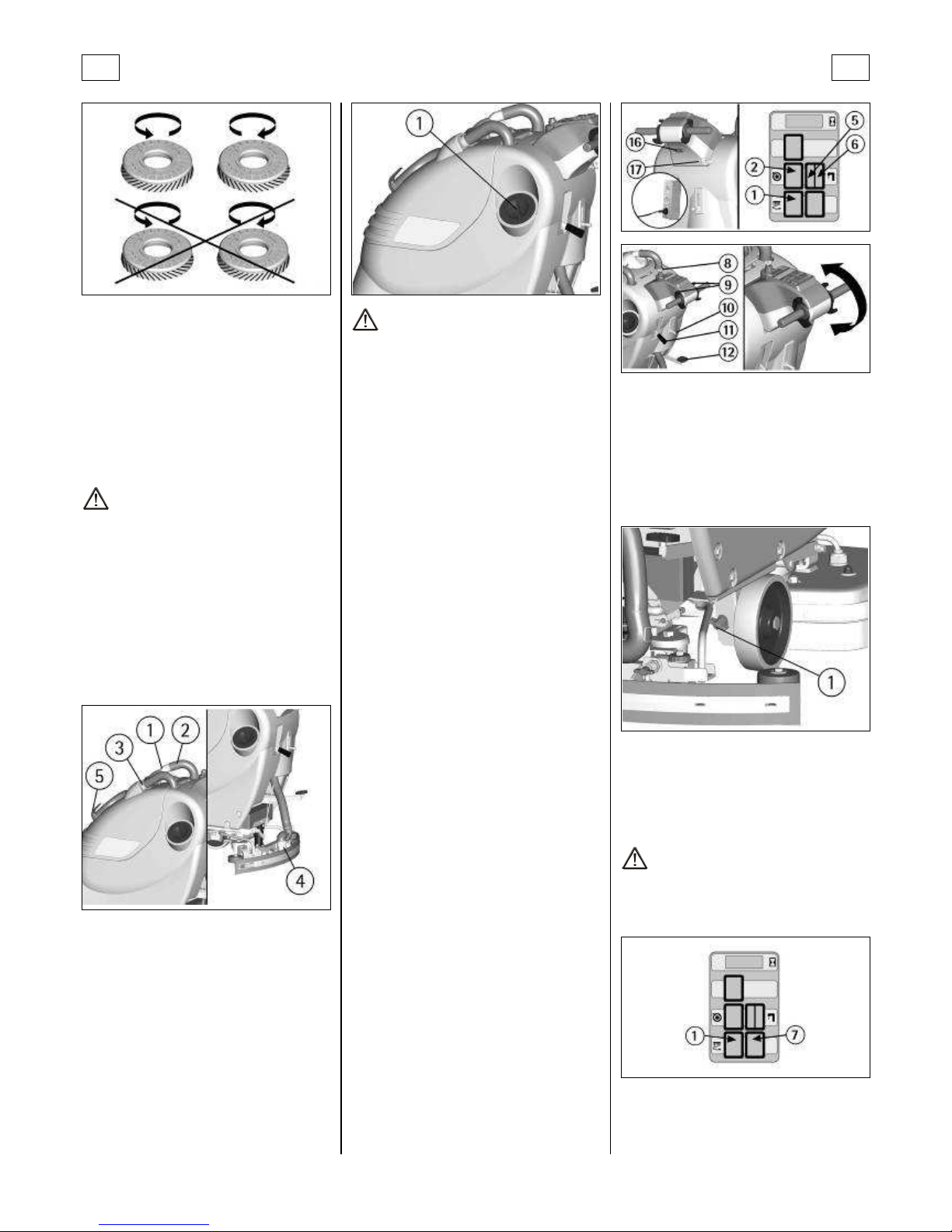
2. Unscrew the brackets (1+2) that secure the
machine to the pallet.
3. Move the machine backwards, as indicated in
the figure, avoiding heavy contacts to m echanical parts.
4. Keep the pallet for eventual transport.
SQUEEGEE ASSEMBLY
With the squeegee support lowered, slide the
two stud bolts (1) placed on the upper part of the
squeegee, inside the slots on the support. Block
the squeegee by rotating the lever (2) clockwise.
Insert the squeegee hose (3) into its coupling, respecting its position as indicated in the figure.
ADJUSTMENT OF THE SQUEEGEE HEIGHT
The squeegee must be adjusted in height depending on the rubber we ar. In o rder to guarantee a perfect drying during the operation, the
lower blade of the rear squeegee rubber (4) must
work slightly bent backwards (operator side) in
uniformed way in all its length.
Acting clockwise upon the two registers (5) it is
possible to increase the bending of the rubber.
Acting counterclockwise it is possible to decrease the rubber bending.
A label placed near the two registers (5) indicates
rotation sense to increase or reduce the height.
Note: The wheels of the squeegee support must
be adjusted through the registers (5) at th e same
height so that the squeegee works parallel to the
floor.
ADJUSTMENT OF THE SQUEEGEE INCLINATION
In case of need, to increase the rubber bending
in the central part, it is necessary to tilt the
squeegee body rotating counterclockwise the
register (6). To increase the rubber bending on
the squeegee extremities, rota te the register
clockwise.
SPLASH GUARD ASSEMBLY
The two splash guards have to be assembled
onto the brushes base group. Insert the metal
strips inside the suitable slots present on the
rubber. Place the round hol e at the flat extremity
of the strip onto the screw placed in the front
part of the brushes base group. Secure the strips
through the nut blocking it.
Hook the spring in the rear part of the brushes
base group to the slot place d at the extremity of
the metal strip still free. Please act as above for
both the splash guard rubbers, paying attention
to reduce to the minimum the gap between the
two rubbers in the front part o f the brushes base
group.
With brushes assembled, the splash guard must
slightly touch the floor.
MANUAL ASSEMBLY OF THE BRUSHES
ATTENTION:
Check that the mains plug is disconnected.
1. Acting upon the pedal (12) lift the brushes
base group.
2. With the brushes base g roup in lift ed position,
insert the brushes into their plate seat underneath the brushes base turning them until the
three metal buttons are properly seated in their
slots; rotate energically the brushes to push the
button towards the coupling spring until they
get blocked.
The figure shows the rotating sense for brushes
coupling.
For the brushes bases ruby45e and ruby55e, we
suggest to invert daily the brushes position, in
order to guarantee a longer operating life of
them. Whenever brushes were deformed we
suggest to reassemble them in the s ame position,
avoiding that the different inclination of the bristles causes excessive motor overload or troublesome vibrations.
Page 7
GB GB
18
AUTOMATIC BRUSH ASSEMBLY (ruby50e)
Put the brush onto the floor next to the brush
base.
1. Check that there is the electric supply.
2. Lift the brush base acting upon the pedal.
3. Move the machine so that the brush base
gets over the brush.
4. Lower slowly the brush base acting upon the
pedal and check that it is centred onto the brush.
5. Press the switch of the brush motor.
6. Act shortly onto the lever presence so that
the brush buttons get coupled in their plate seats.
ATTENTION:
Use only brushes supplied with the machine or
the ones indicated in the paragraph “RECOMMENDED BRUSHES”. The use of other brushes
can compromise security.
RECOVERY TANK
Check that the cove r of the suction filter (1) is
correctly secured, after rotating the levers and
that the suction motor hose (2) is correctly connected.
Verify also that the squeegee hose is co rrectly inserted into the seats (3 and 4) and that the exhaust hose plug (5) placed in the front part of the
machine, is closed.
DETERGENT SOLUTION TANK
The capacity of the detergent solution tank is indicated in the technical data.
Open the screw plug (1) placed in the rear left
part of the machine and fill the detergent solution tank with clean water at a maximum temperature of 50°C. Add the liquid detergent in the
percentage and conditions foreseen by the
manufacturer. To avoid excessive foam presence,
which could cause problems to the suction motor, use the minimum percentage of detergent.
Screw down the plug to close the tank.
ATTENTION:
Use always low foam detergent. To avoid foam
presence, before starting working operation, introduce into the recovery tank a minimum quantity of anti-foam product.
Never use pure acid.
FLOOR CLEANING
STARTING OF THE MACHINE
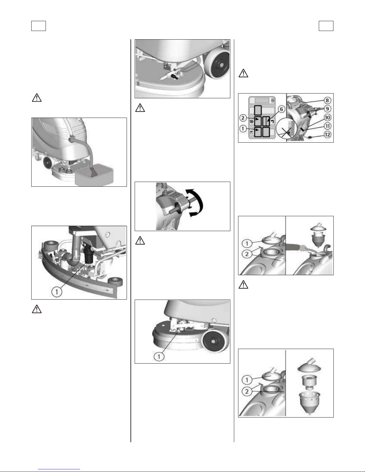
The machine is equipped with a mains cable
complete with a plug for the connection to the
mains system and with a socket connector to insert inside the plug (16) situated underne ath the
instrument board.
1. Insert the socket inside the machine plug (16).
2. Hook the cable onto the support (17) to avoid
that probable tears can damage the socket.
3. Insert the plug into the appropriate mains
socket and check that on the instrument board
the signal lamp for tension presence comes on
(5).
4. For machines equipped with key switch (see
under "OPTIONAL ACCESSORIES”), turn the key (8)
clockwise to switch on the machine, counterclockwise to switch it off.
5. Press the brushes motor switch (1).
6. Press the switch of the suction motor (2) and
this will start to function.
7. Acting upon the solution valve lever (10) adjust the solution detergent quantity bringing the
floor uniformly wet, avoiding the lea kage of detergent from the splash guards. Always co nsider
that the co rrect quantity of solution detergent
depends on type of floor, dir tiness and ma chine
speed.
8. For machines optionally equipped with solenoid valve (see under "OPTIONAL ACCESSORIES")
the flow of detergent solution will be activated
automatically, once the solution valve has been
opened through the lever (10), act ing upon the
levers presence (9). On th e instru ment board the
signal lamp of the open solution valve will come
on (6). Releasing these levers, flow will stop
automatically.
9. Acting upon the brushes base lifting pedal
(12) lower the brushes base.
10. Acting upon t he squeeg ee lifting lever (11)
lower the squeegee.
11. Activating the levers (9), the brushes will start
rotating transferring to the machine a forward
movement. The squeegee will start drying the
floor.
12. During the fi rst meters check that the detergent solution flow is appropriate and that the
squeegee adjustment guarantees a perfect drying action.
ADJUSTMENT OF THE BRUSHES PRESSURE (OPTIONAL)
Through the register (1) pla ced in the inner part
near the front right wheel, i t is possible to adjust
the brushes pressure on the cleaned surface.
By turning the wing nut clockwise the pressure
increases, rotating the wing nut counterclockwise, the pressure decreases.
This device allows a more efficient cleaning action also on very difficult and dirty surfaces.
BRUSHES MOTOR OVERLOAD PROTECTION DEVICE
The machine is equipped with a protection device (7) that intervenes in case of an overload of
the brushes motor disconnecting the motor. If
the protection device intervenes again and often,
contact the authorized technical assistance.
ATTENTION:
To reset the brushes motor, turn off the brushes
motor switch (1) for a few seconds and turn i t on
again, rearm the push button of the protection
device (7).
OVERFLOW DEVICE
In order to avoid serious da mages to the suction
motor, the machine is equipped with a float that
intervenes when the recovery t ank is full, closing
the suction hose and stopping the suction.
Page 8
GB GB
19
When this happens, it is ne cessary to t ake off the
plug from the mains socket and to empt y th e recovery tank.
1. Hold the exhaust hose placed in the front part
of the machine.
2. Take off the exhaust plug acting upon its
lever and empty the recovery tank into appropriate containers, according to the standard norms.
ATTENTION:
This operation must be carried out using gloves
to protect from contact with dangerous solutions
EMPTYING DETERGENT SOLUTION
To empty the detergent solution remained in the
solution tank:
1. Bring the machine to an appropriate place for
tanks draining.
2. Unscrew the exhaust plug (1).
ATTENTION:
This operation must be carried out using gloves
to protect from contact with dangerous solutions.
EMPTYING DEVICE DETERGENT SOLUTION (OPTIONAL)
To recover the detergent solution, it is nec essary
to use the emptying device provided for the
purpose and proceed as follows:
1. Unhook the hose.
2. Open the solution valve directing the jet into
a collecting container.
3. When the operation has been completed,
close the solution valve.
Put the hose back into i ts position, pl acing it into
the spring.
ATTENTION:
This operation must be carried out using gloves
to protect from contact with dangerous solutions.
FORWARD MOVEMENT
The traction of these ma chines is given by the
brushes that, working on an inclined axle, transmit to the machine the forward movement. The
effect is bigger with brush es that have thicker
bristles.
STOP
Releasing the lever of the presence, brushes rotation will end, stopping the machine movement.
ATTENTION:
Moving the machine backwards, make sure that
the squeegee is lifted.
ADJUSTMENT OF BRUSHES INCLINATION (OPTIONAL ruby45e, ruby55e)
Through the register (1) placed on the brushes
base group, it is possible to adjust the brushes
inclination increasing/decreasing the speed of
the machine. A label pl aced on the brushes base
indicates the adjustment levels LOW/FAST.
STOP OF THE MACHINE AFTER
CLEANING OPERATION
Before executing any type of maintenance:
1. Close the solution valve through the lever (10).
2. For machines optionally equipped with solenoid valve (see under "OPTIONAL ACCESSORIES")
the flow of detergent solution will stop automatically when the levers (9) are released. On the
instrument board the signal lamp of the open solution valve will go off (6).
3. Lift the brushes base acting upon the pedal
(12).
4. Lift the squeegee acting upon the lever (11).
5. Turn the brushes motor switch off (1).
6. Turn the suction motor switch off (2).
7. Take off the plug from the mains socket.
8. Bring the machine to an appropriate place for
tanks draining.
ATTENTION:
The machine is not equipped with a parking
brake, therefore do not leave it on slopes.
DAILY MAINTENANCE
RECOVERY TANK CLEANING
1. Hold the exhaust hose placed in the front part
of the machine.
2. Take off the exhaust plug acting upon its
lever and empty the recovery tank into appropriate containers (see under "OVERFLOW DEVICE").
3. Take off the suction cover (1) after rotating
the blocking levers (2).
4. Take off the filter and filter protection.
5. Rinse the tank with a water jet.
ATTENTION:
This operation must be carried out using gloves
to protect from contact with dangerous solutions.
SUCTION FILTER CLEANING
1. Take off the suction cover (1) after rotating
the blocking levers (2).
2. Take off the filter and filter protection.
3. Clean all parts with a water jet especially inside surfaces and filter bottom.
4. Carry out carefully the cleaning operations.
5. Reassemble all parts.
BRUSHES CLEANING
Disassemble the brushes and clean them wi th a
water jet (for the brushes disassembly, check
“BRUSHES DISASSEMBLY” paragraph).
Page 9
GB GB
20
BRUSHES DISASSEMBLY (ruby45e, ruby55e)
ATTENTION:
Check that the plug is disconnected.
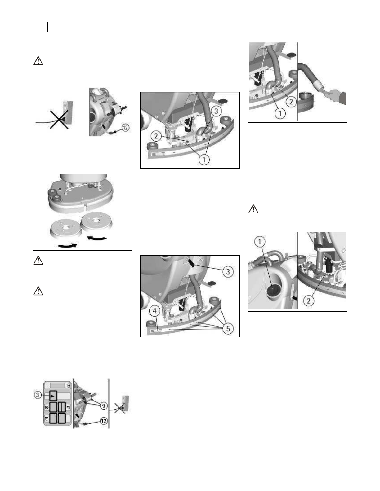
1. Lift the brushes base lowering the pedal (12).
2. With the brushes base in lifted position, turn
the brush in its rotating sense, until it is released
from the brush holder plate se at as in dicated in
the figure. The figure shows the rotating sense
for brushes release.
ATTENTION:
The execution of brushes disassembly operations
with electric supply on, may cause damages to
hands.
ATTENTION:
The handling of the brushes operation must be
carried out using suitable gloves to prot ect both
mechanically from contact with the bristl es and
the chemical risk of contact with dangerous solutions.
AUTOMATIC BRUSH DISASSEMBLY (ruby50e)
1. Lift the brushes base lowering the pedal (12).
2. Press the levers (9) backwards and simultaneously press the push button (3) of the brush release. The brush motor turns the opposite way
and makes drop the brush onto the floor.
3. Release the push button and levers.
4. Take off the plug from the electric mains
socket.
SQUEEGEE CLEANING
Keeping the squeegee clean guarantees alwa ys
the best drying action.
For the cleaning it is necessary to:
1. Take off the squeegee hose (3) from the coupling.
2. Disassemble the squeegee from the support
rotating the lever (2) counterclockwise sliding
the stud bolts (1) in their slots.
3. Clean with care the internal part of the
squeegee inlet eliminating eventual dirt residuals.
4. Clean with care the squeegee rubbers.
5. Reassemble all parts..
WEEKLY MAINTENANCE
REAR SQUEEGEE RUBBER REPLACEMENT
Check the squeegee rubber wear and eventu ally
turn or replace it.
For the replacement it is necessary to:
1. Lift the squeegee acting upon the lever (3).
2. Release the hook (4) of the rubber holder
blade and take the rubber off.
3. Turn the rubber to a new side or replace it.
To reassemble the squeegee repeat reverse the
operations above-mentioned, inserting the rubber on the guides (5) and blocking it with the
rubber holder blade.
SQUEEGEE HOSE CLEANING
Weekly or in case of insufficient suction, it is necessary to check that the squeegee hose is not obstructed. Eventually, to clean it, proceed as follows:
1. Take off the hose from the squeegee coupling
(1) and release the guide spring of the squeegee
hose (2).
2. Wash the inside of the hose with a water jet,
from the squeegee hose side.
3. To reassemble the hose repeat reverse the
operations above-mentioned.
CLEANING OF SOLUTION TANK AND FILTER
1. Bring the machine to an appropriate place for
tanks draining.
2. Unscrew the solution tank cap (1).
3. Unscrew the exhaust plug (2).
3a. The machines equipped with the optional
device of the solution drainage, it is sufficient to
open the solution valve of the devi ce (see un der
"EMPTYING DEVICE DETERGENT SOLUTION").
4. Rinse with a water jet the solution tank.
5. Rinse the solution tank filter placed inside the
exhaust plug, under the machine.
6. Reassemble all parts and close, if present, the
solution valve of the drainage device.
ATTENTION:
This operation must be carried out using gloves
to protect from contact with dangerous solutions.
TWO-MONTHLY MAINTENANCE
FRONT SQUEEGEE RUBBER REPLACEMENT
Check the wear of the squeegee rubber and
eventually replace it.
For the replacement it is necessary to:
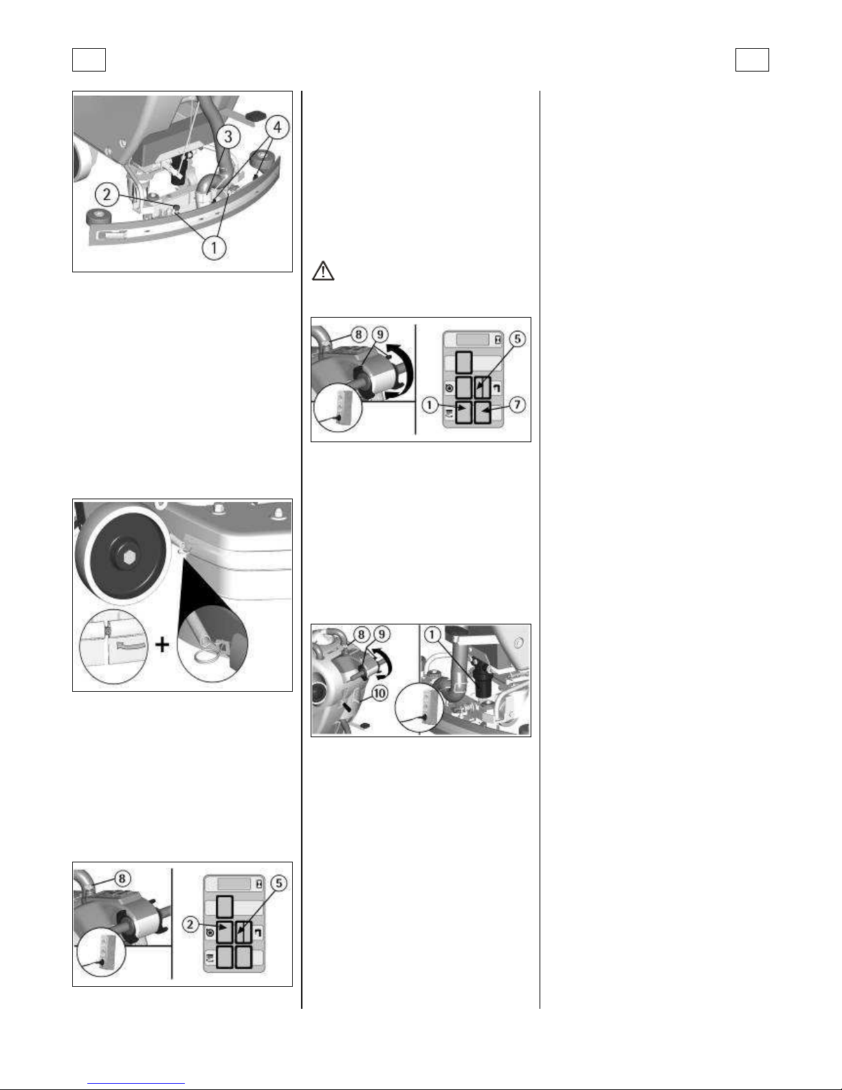
1. Take off the squeegee hose (3) from its coupling.
2. Lift the squeegee acting upon the lever (fig. 1,
pos. 19).
3. Disassemble the squeegee from the support
rotating the lever (2) countercloc kwise and sliding the stud bolts (1) in their slots.
4. Unscrew the wing nuts (4) in the front part of
the squeegee.
5. Take off the rubber holder blade.
6. Replace the front rubber.
7. Reassemble all parts.
Page 10
GB GB
21
SIX-MONTHLY MAINTENANCE
SPLASH GUARD REPLACEMENT
1. Release the spring in the rear part of the
brushes base group from the slot placed at the
extremity of the metal strip.
2. Unscrew the nut on the front part of the
brushes base group and take off the metal strips.
3. Replace the splash guard rubbers and follow
the assembling instructions at “SPLASH GUARD
ASSEMBLY” paragraph.
With brushes assembled, the splash guard must
slightly touch the floor.
The checking of all the other foreseen machine
operations is left to the authorized technical assistance.
TROUBLESHOOTING GUIDE
THE SUCTION MOTOR DOES NOT WORK
1. Verify that the signal light for presence of the
tension (5) is on, if necessary, check th at the plug
is correctly inserted in a functioning mains socket.
2. The model equipped with the key switch (see
under "OPTIONAL ACCESSORIES”), turn the key (8)
clockwise to switch on the machine.
3. Verify that the switch (2) is on.
If the proble m persists, please contact the authorized technical assistance.
THE BRUSHES MOTOR DOES NOT WORK
1. Verify that the signal light for presence of the
tension (5) is on, if necessary, check th at the plug
is correctly inserted in a functioning mains socket.
2. The model equipped with the key switch (see
under "OPTIONAL ACCESSORIES”), turn the key (8)
clockwise to switch on the machine.
3. Verify that the switch (1) is on.
4. Activate the levers for presence (9).
5. Check that the brushes motor overload protection device (7) did not intervene; in this case,
rearm it.
If the proble m persists, please contact the authorized technical assistance.
ATTENTION:
Never leave the socket inserted in the mains plug
when the machine is not being used.
INSUFFICIENT WATER ON THE BRUSHES
1. Check that the solution valve lever (10) is
open.
2. Check the level of the liquid in the solution
tank.
3. Check that solution filter (1) is clean.
4. If the machine is equipped with the solenoid
valve (see under "OPTIONAL ACCESSORIES”), act
upon the levers presence (9).
5. The model equipped with the key switch (see
under "OPTIONAL ACCESSORIES”), turn the key (8)
clockwise to switch on the machine.
If the proble m persists, please contact the authorized technical assistance.
THE MACHINE DOES NOT CLEAN PROPERLY
1. The brushes do not have the suitable bristle
dimension: use only original brushes. For advice,
contact the authorized technical assistance.
2. The brushes have got worn bristles. Check the
brushes wear condi tion and eventually replace
them (the brushes have to be r eplaced when the
bristles have reached a height of about 15mm).
To replace the brushes, see instruc tions at paragraph “BRUSHES DISASSEMBLY” and “BRUSHES
ASSEMBLY”.
3. The solution detergent is insufficient: open
more the solution valve.
4. Check that the liquid detergent is in the recommended percentage.
Contact the authorized technical assistance for
advice.
THE SQUEEGEE DOES NOT DRY PERFECTLY
1. Check that the squeegee rubbers are clean.
2. Check the height and inclination of the
squeegee (see se ction “SQUEEGEE ” in “BEFORE
USE”).
3. Check that the suction hose is correctly inserted in the proper seat on the recovery tank.
4. Clean the suction filter.
5. Replace the rubbers if worn out.
6. Check that the suction motor switch is on.
7. Check that the recovery tank is empty.
EXCESSIVE FOAM PRODUCTION
Check that low foam detergent has been used.
Eventually add small quantities of anti foam liquid into the recovery tank.
Please be aware that a bigg er qu antity of foam is
produced when the floor is no t ver y dirty. In this
case please dilute detergent solution.
Page 11
GB GB
22
PROGRAMMED MAINTENANCE
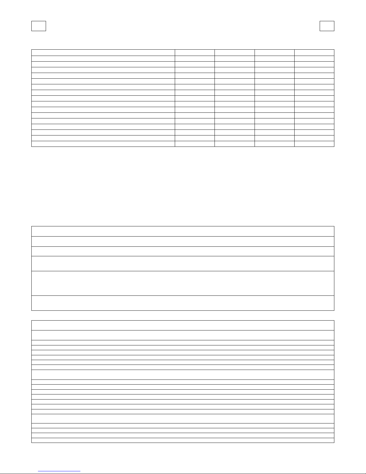
INTERVENTION DAILY WEEKLY TWO-MONTHLY SIX-MONTHLY
RECOVERY TANK CLEANING •
SUCTION FILTER CLEANING •
SOLUTION TANK FILTER CLEANING •
BRUSHES CLEANING •
BRUSHES DISASSEMBLY •
SQUEEGEE CLEANING •
FRONT SQUEEGEE RUBBER REPLACEMENT •
REAR SQUEEGEE RUBBER REPLACEMENT •
SPLASH GUARD RUBBER REPLACEMENT •
SQUEEGEE ADJUSTMENT CHECK •
SQUEEGEE HOSE CLEANING •
SOLUTION TANK CLEANING •
BRUSHES MOTOR CHECK •
SUCTION MOTOR CHECK •
BRUSHES BASE GROUP CHECK •
SCREW TIGHTENING •
RECOMMENDED BRUSHES
Brushes must be chosen depending on type of floor and dirt to be removed.
The employed material and the bristles diameter are the ele ments that distinguish different types of brushes.
MATERIAL CHARACTERISTICS
PPL (Polypropylene) Good wear resistance. Maintains characteristics with hot water up to 60°C. It is not hygroscopic.
NYLON
Excellent wear resistance, even with hot water over 60°C. It is hygrosco pic. It looses its physical characteristics over the
time.
TYNEX Nylon bristles with grains of abrasive material. Use with caution in order not to mark the floor or ruin the polishing.
BRISTLES THICKNESS
Thicker bristles are more rigid and must be used on smooth floor o r floor with small joints.
On irregular floors with deep joints or relieves, it is recommended to use softer bristles which penetrate more easily and
deeper. Please be aware that when brushes bristles ar e worn out an d therefore too small, they become rigid and unable
to penetrate and clean deeper. This ma y also happen with thicker bristl es creating brush vibration.
PAD HOLDER
Pad holder is recommended to clean smooth surfaces. It has ancho r points which permit the blocking of the abrasive pad
during work.
MACHINE CODE QUANTITY DESCRIPTION USE
ruby 45e 48901010 2 Brush PPL 0,3 Ø 235 Irregular floors with large joints.
48901020
2
Brush PPL 0,4 Ø 235
Normal floors.
48901030
2
Brush PPL 0,5 Ø 235
Smooth floors with small joints and persistent dirt.
48901040
2
Brush NYLON 0,5 Ø 235
Smooth
floors with small joints and persistent dirt.
48901050
2
Brush PPL 0,6 Ø 235
Smooth floors with small joints and persistent dirt.
48901060
2
Brush TYNEX Ø 235
Floors of resistant material and particularly dirty.
48801010
2
Pad holder Ø 230
For pad
s of 9”, for smooth surfaces cleaning.
ruby 55e 48901110 2 Brush PPL 0,3 Ø 285 Irregular floors with large joints.
48901120
2
Brush PPL 0,4 Ø 285
Normal floors.
48901130
2
Brush PPL 0,5 Ø 285
Smooth floors with small joints and persistent dirt.
4890
1140 2 Brush NYLON 0,5 Ø 285
Smooth floors with small joints and persistent dirt.
48901150
2
Brush PPL 0,6 Ø 285
Smooth floors with small joints and persistent dirt.
48901160
2
Brush TYNEX Ø 285
Floors of resistant material and particularly dirty.
48901170
2
Brush PPL 0,9 Ø 285
Smooth floors with small joints and persistent dirt.
48801020
2
Pad holder Ø 280
For pads of 11”, for smooth surfaces cleaning.
ruby 50e 48902010 1 Brush PPL 0,3 Ø 508 Irregular floors with large joints.
48902020
1
Brush P
PL 0,7 Ø 508
Smooth floors with small joints and persistent dirt.
48902030
1
Brush PPL 0,9 Ø 508
Smooth floors with small joints and persistent dirt.
48902040
1
Brush TYNEX Ø 508
Floors of resistant material and particularly dirty.
48802010
1
Pad ho
lder Ø 495
For pads of 20”, for smooth surfaces cleaning
.
 Loading...