

Flomotion Systems EM6100 User Manual

EM6100
Portable Handheld Ultrasonic Flow Meter

EM6100 Handheld Portable Ultrasonic Flowmeter Ver.8.08
Flomotion Systems, Inc. EM6100
2

EM6100 Handheld Portable Ultrasonic Flowmeter Ver.8.08
EM6100
Portable Handheld
Ultrasonic Transit-Time Flow Meter
165 Creekside Drive, Suite 112, Buffalo, NY 14228-2103
Flomotion Systems, Inc. EM6100
DECEMBER 2010
Flomotion Systems, Inc.
Toll Free: (800) 909-3569
Tel: (716) 691-3941 Fax: (716) 691-1253
info@FlomotionSystems.com
www.FlomotionSystems.com
3

EM6100 Handheld Portable Ultrasonic Flowmeter Ver.8.08
Table of Contents
1. Introduction ............................................................................................................................................6
§1.1 Preface............................................................................................................................................6
§1.2 Features .......................................................................................................................................... 6
§1.3 Principle of Measurement ..............................................................................................................7
§1.4 Parts Identification .........................................................................................................................8
§1.5 Typical Applications..................................................................................................................... 10
§1.6 Data Integrity and Built-in Time-Keeper ..................................................................................... 10
§1.7 Product Identification................................................................................................................... 11
§1.8 Specifications ............................................................................................................................... 11
2. Starting Measurement...........................................................................................................................12
§2.1 Built-in Battery............................................................................................................................. 12
§2.2 Power On...................................................................................................................................... 12
§2.3 Keypad .........................................................................................................................................13
§2.4 Menu Windows ............................................................................................................................ 14
§2.5 Menu Windows Arrangement....................................................................................................... 15
§2.6 Steps to Configure the Parameters ...............................................................................................15
§2.7 Transducers Mounting Location................................................................................................... 17
§2.8 Transducers Installation................................................................................................................ 19
§2.8.1 Transducers Spacing.............................................................................................................. 19
§2.8.2 V-method Installation ............................................................................................................ 20
§2.8.3 Z-method Installation ............................................................................................................ 20
§2.8.4 W-method Installation ...........................................................................................................21
§2.9 Installation Checkup..................................................................................................................... 22
§2.9.1 Signal Strength ...................................................................................................................... 22
§2.9.2 Signal Quality........................................................................................................................ 22
§2.9.3 Total Transit Time and Delta Time ........................................................................................22
§2.9.4 Time Ratio between the Measured Total Transit Time and the Calculated Time .................. 23
3. How To................................................................................................................................................. 24
§3.1 How to judge if the instrument is working properly ....................................................................24
§3.2 How to judge the liquid flow direction......................................................................................... 24
§3.3 How to change between units systems ......................................................................................... 24
§3.4 How to select a required flow rate unit ........................................................................................24
§3.5 How to use the totalizer multiplier............................................................................................... 24
§3.6 How to start or stop the totalizers................................................................................................. 25
§3.7 How to reset the totalizers............................................................................................................ 25
§3.8 How to restore the flow meter with default setups....................................................................... 25
§3.9 How to use damping..................................................................................................................... 25
§3.10 How to use the zero-cutoff function........................................................................................... 25
Flomotion Systems, Inc. EM6100
4

EM6100 Handheld Portable Ultrasonic Flowmeter Ver.8.08
§3.11 How to setup a zero point........................................................................................................... 25
§3.12 How to get a scale factor for calibration ....................................................................................26
§3.13 How to use the operation lock.................................................................................................... 26
§3.14 How to use the built-in data logger ............................................................................................ 26
§3.15 How to use the Frequency Output.............................................................................................. 26
§3.16 How to use the Totalizer Pulse Output ....................................................................................... 27
§3.17 How to produce an alarm signal................................................................................................. 27
§3.18 How to use the built-in Buzzer...................................................................................................28
§3.19 How to use the OCT output........................................................................................................ 28
§3.20 How to modify the built-in calendar ..........................................................................................28
§3.21 How to adjust the LCD contrast................................................................................................. 28
§3.22 How to use the RS232 serial interface .......................................................................................28
§3.23 How to view the Date Totalizers ................................................................................................ 29
§3.24 How to use the Working Timer................................................................................................... 29
§3.25 How to use the manual totalizer................................................................................................. 29
§3.26 How to check the ESN and other minor details..........................................................................29
§3.27 How to know how long the battery will last............................................................................... 29
§3.28 How to charge the built-in battery.............................................................................................. 29
4. Menu Window Details.......................................................................................................................... 30
5.Troubleshooting.....................................................................................................................................35
§5.1 Power-on Error Displays and Counter-Measures ......................................................................... 35
§5.2 Error Codes, Causes and Solutions .............................................................................................. 35
§5.3 Other Problems and Solutions......................................................................................................37
6. Communication Protocol...................................................................................................................... 38
§6. 0 General ........................................................................................................................................ 38
§6.1 Interface Pin-out Definition.......................................................................................................... 38
§6.2 the Protocol ..................................................................................................................................39
§6.3 Protocol Prefix Usage................................................................................................................... 40
§6.4 Codes for the Keypad................................................................................................................... 41
7. Warranty and Service ...........................................................................................................................42
§7.1 Warranty ....................................................................................................................................... 42
§7.2 Service..........................................................................................................................................42
§7.2 Software Upgrade Service............................................................................................................ 42
Flomotion Systems, Inc. EM6100
5

EM6100 Handheld Portable Ultrasonic Flowmeter Ver.8.08
1. Introduction
§1.1 Preface
The EM6100 (Version 8.xx) series ultrasonic flow meter that has been manufactured with patented
technologies and is equipped with more functions and advanced performance than our previous versions.
The Version 8.xx series ultrasonic flow meter has been upgraded based on the Version 7.xx series
ultrasonic flow meter, which is still the main product line of the company. The new Version 8.xx retains
most of the features and functions of the previous versions: the pulse measurement technology, the
ultrasonic igniting and the small signal receiving circuits etc. The main improvements are made on the
battery supply circuit and on the transmitting circuits.
The EM6100 Series flow meter features ease of operation, high accuracy and outstanding reliability,
while the software provides a very user friendly interface and many more functions. It employs a
patented balanced lower voltage multi-pulse igniting circuit which increases the anti-interference ability
so that the flow meter will work properly even in demanding industrial environments such as those with
power frequency transformers working nearby.
Other outstanding features:
---- signal receiving circuits feature self-adapting performance so as to ensure that the user can easily
operate the instrument without any adjustment.
---- built-in rechargeable Ni-H battery can work continuously for more than 12 hours without recharge.
§1.2 Features
* 0.5% of linearity
* 0.2% of repeatability
* 4 flow totalizers
* Patent balanced lower-voltage multi-pulse ultrasonic igniting
* built-in date totalizers
* built-in data-logger
* Work properly near transformers
* 0.5 second totalizing period
* 100 Pico-second resolution of time measurement
Flomotion Systems, Inc. EM6100
6
EM6100 Handheld Portable Ultrasonic Flowmeter Ver.8.08
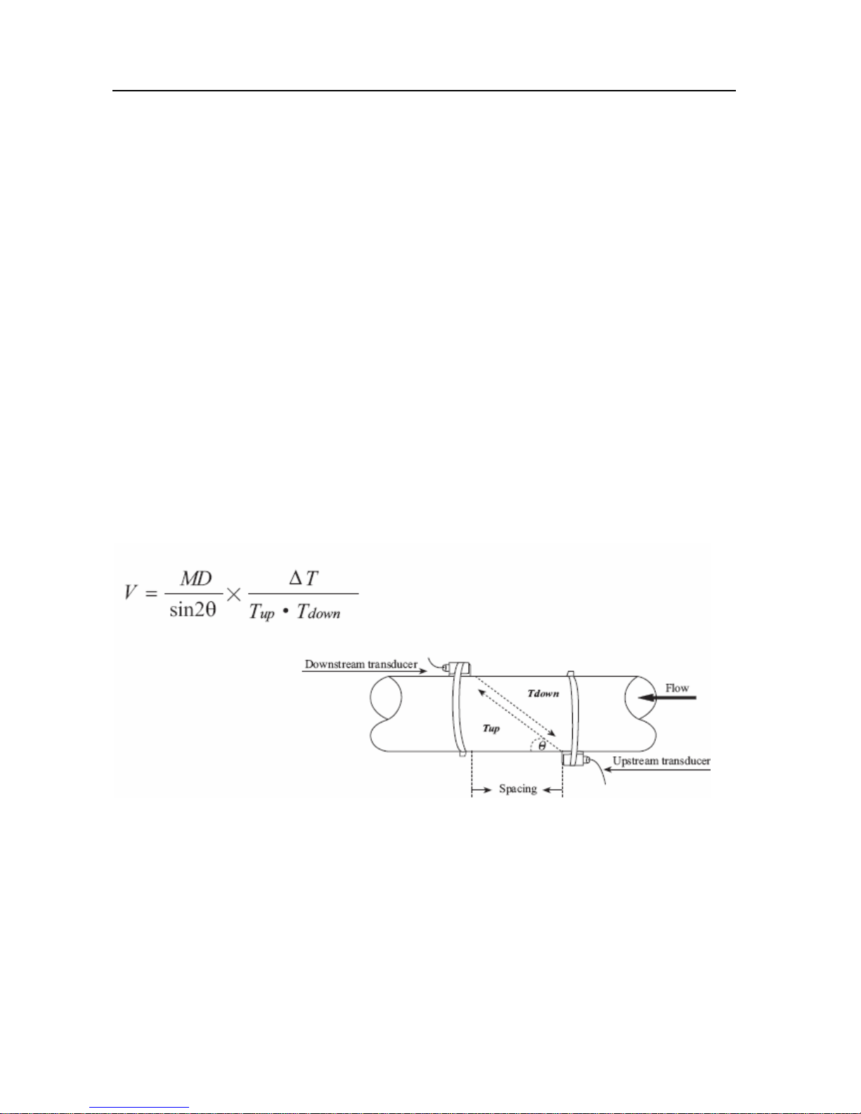
§1.3 Principle of Measurement
The EM6100 ultrasonic flow meter is designed to measure the fluid velocity of liquid within a closed
conduit. The transducers are a non-contacting, clamp-on type, which will provide benefits of
non-fouling operation and easy installation.
The EM6100 transit time flow meter utilizes two transducers that function as both ultrasonic
transmitters and receivers. The transducers are clamped on the outside of a closed pipe at a specific
distance from each other. The transducers can be mounted in V-method where the sound transverses
the pipe twice, or W-method where the sound transverses the pipe four times, or in Z-method where the
transducers are mounted on opposite sides of the pipe and the sound crosses the pipe once. This
selection of the mounting method depends on pipe and liquid characteristics. The flow meter operates
by alternately transmitting and receiving a frequency modulated burst of sound energy between the two
transducers and measuring the transit time that it takes for sound to travel between the two transducers.
The difference in the transit time measured is directly and exactly related to the velocity of the liquid in
the pipe, as shown in Figure 1.
Where
θ is the include angle to the flow direction
M is the travel times of the ultrasonic beam
D is the pipe diameter
Tup is the time for the beam from upstream transducer to the downstream one
Tdown is the time for the beam from downstream transducer to the upstream one
ΔT=Tup –Tdown
Flomotion Systems, Inc. EM6100
7
EM6100 Handheld Portable Ultrasonic Flowmeter Ver.8.08
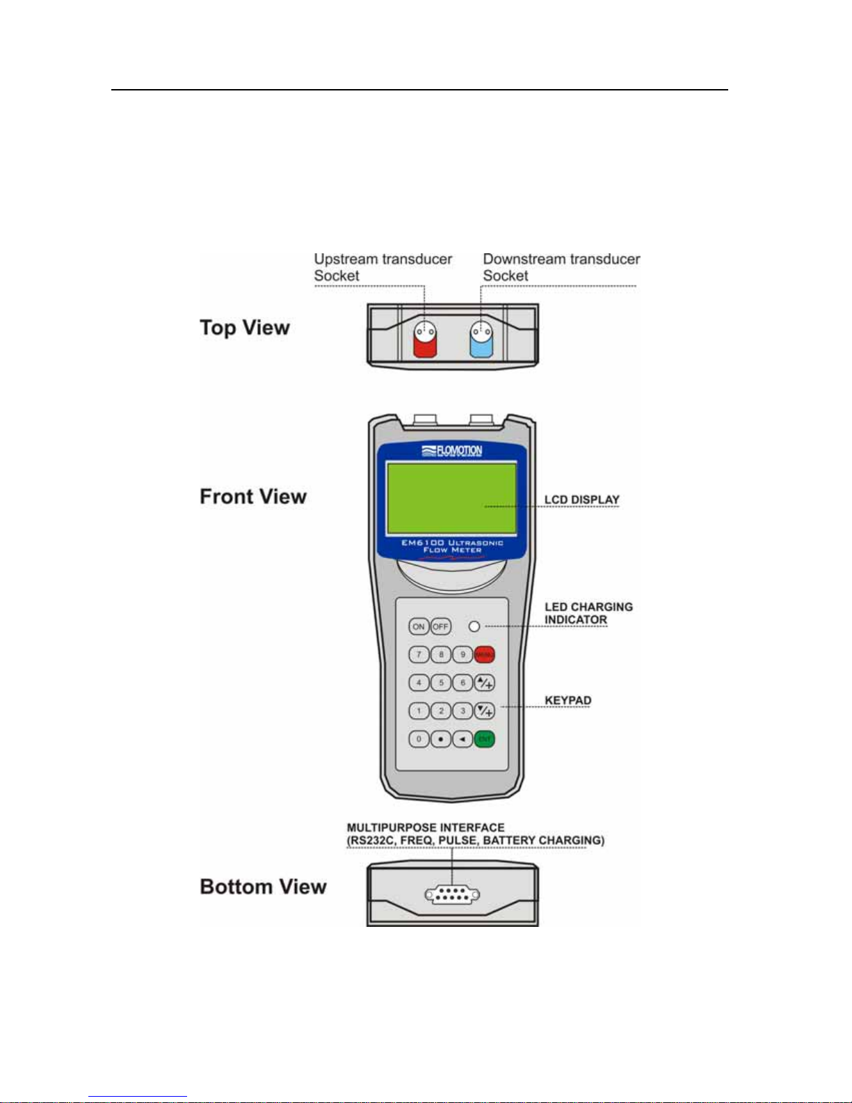
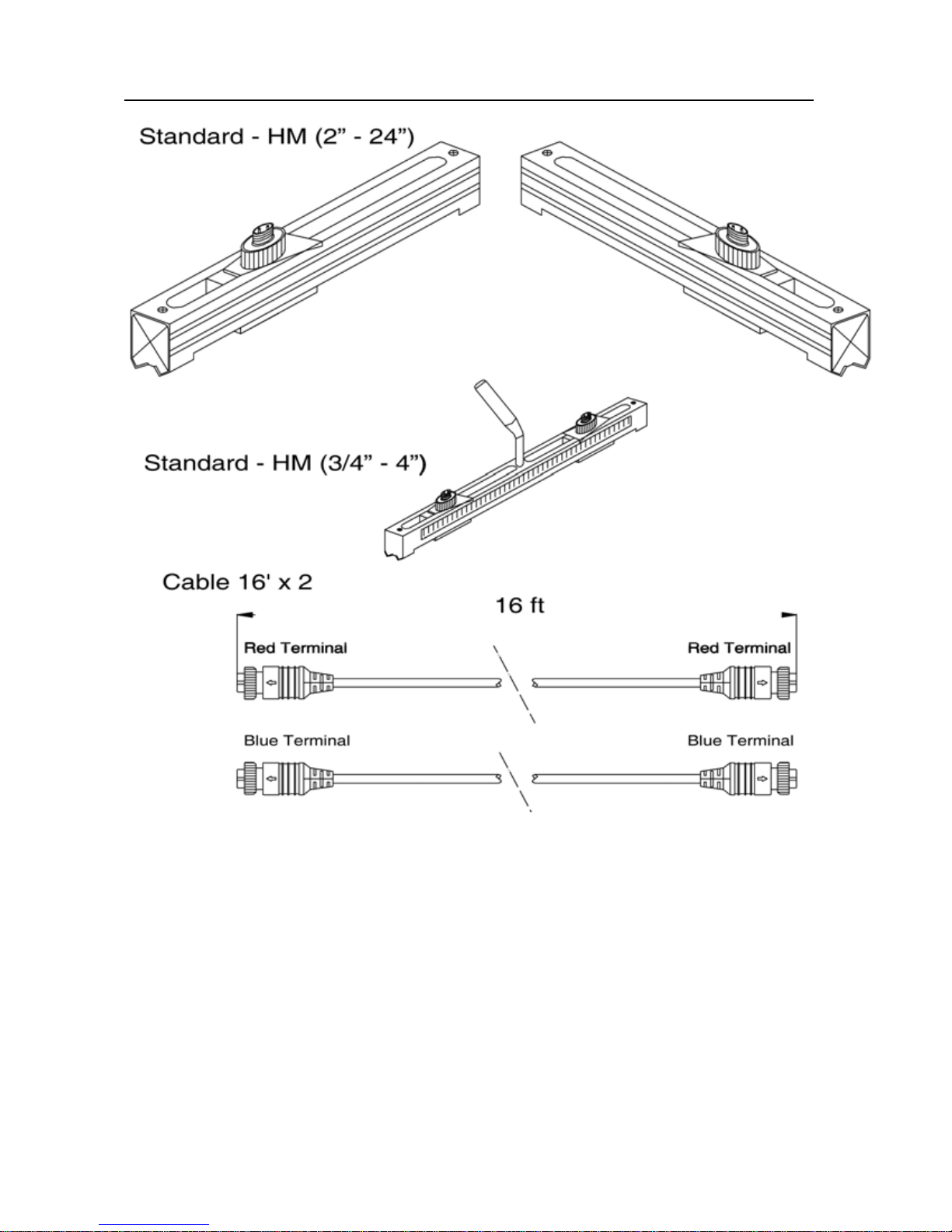
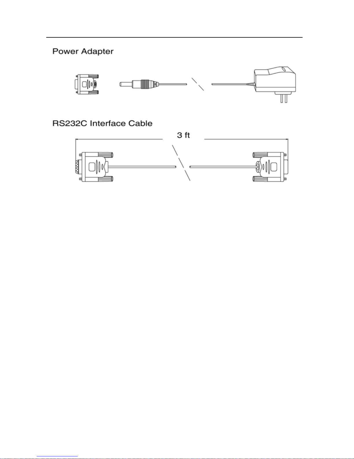
§1.4 Parts Identification
Converter:
Flomotion Systems, Inc. EM6100
8
EM6100 Handheld Portable Ultrasonic Flowmeter Ver.8.08
Flomotion Systems, Inc. EM6100
9
EM6100 Handheld Portable Ultrasonic Flowmeter Ver.8.08
§1.5 Typical Applications
The EM6100 flow meter can be applied to a wide range of measurements. The measured pipe range is
0.75 - 120 inch. A variety of liquid applications can be accommodated: ultra-pure liquids, potable water,
chemicals, raw sewage, reclaimed water, cooling water, river water, plant effluent, etc. Because the
instrument and transducers are non-contacting and have no moving parts, the flow meter can not be
affected by system pressure, fouling or wear. Standard transducers are rated to 230 ºF (110 ºC.) Higher
temperatures can be accommodated. For further information, please consult the manufacturer for
assistance.
§1.6 Data Integrity and Built-in Time-Keeper
All user-inputted configuration values are retained in the built-in non-volatile flash memory that can
store them for over 100 years, even if power is lost or turned off. Password protection is provided to
avoid inadvertent configuration changes or totalizer resets. A time-keeper is integrated in the flow
meter for the index of date totalizing and works as the time base of flow accumulation. It keeps
operating as long as the battery’s terminal voltage is over 1.5V. In case of battery failure, the
time-keeper will not keep running and it will lose proper time values. The user must re-enter proper time
values in case the battery becomes totally exhausted. An improper time value affects no other functions
but the date totalizer.
Flomotion Systems, Inc. EM6100
10

EM6100 Handheld Portable Ultrasonic Flowmeter Ver.8.08
§1.7 Product Identification
Each EM6100 Series flow meter has a unique product identification or ESN written into the software
that can only be modified with a special tool by the manufacturer. In case of any hardware failure, please
provide this number which is located on menu window number M61 when contacting the manufacturer.
§1.8 Specifications
Linearity 0.5%
Repeatability 0.2%
Accuracy ±1% of reading at rates > 0.66 fps (0.2 mps)
Response Time 0-999 seconds, user-configurable
Velocity -53 to +53 fps
Pipe Size 0.75 in – 120 in
Meter, Feet, Cubic Meter, Liter, Cubic Feet, USA Gallon, Imperial
Rate Units
Totalizer 7-digit totals for net, positive and negative flow respectively
Liquid Types Virtually all liquids
Security Setup values Modification Lockout. Access code needs unlocking
Display Alphanumeric 4x16 character, back-lit LCD
Communication
Interface
Transducers S, M, L (M standard)
Transducer Cord Length Standard 2x16 ft
Power Supply
Gallon, Oil Barrel, USA Liquid Barrel, Imperial Liquid Barrel, Million
USA Gallons. User configurable.
RS-232C, baud-rate: from 75 to 57600. Protocol made by the
manufacturer and compatible with that of the FUJI ultrasonic flow
meter. User protocols can be made on enquiry.
3 AAA Ni-H built-in batteries. When fully recharged it will last over
10 hours of operation.
100V-240VAC for the charger
Data Logger Built-in data logger can store over 2000 lines of data
Manual Totalizer 7-digit press-key-to-go totalizer for calibration
Flomotion Systems, Inc. EM6100
11

EM6100 Handheld Portable Ultrasonic Flowmeter Ver.8.08
Housing Material ABS
Case Size 3.4 x 2.6 x 0.79in
Handset Weight 1.2 lbs. with batteries
2. Starting Measurement
§2.1 Built-in Battery
The instrument can operate either from the built-in Ni-H rechargeable battery, which will last over 10
hours of continuous operation when fully recharged, or from an external AC power supply from the
battery charger.
The battery charging circuits employ a scheme of constant-current and constant-voltage. It has a
characteristic of fast charging at the beginning and very slow charging when the battery approaches to
full recharge. Generally, when the green LED starts coming on, the battery would be nearly 95%
recharged and when the red LED is off, the battery would be 98% recharged.
Since the charging current becomes tapered when the battery recharge is nearly completed, i.e. the
charging current becomes smaller and smaller, therefore, there should be no over-recharging problem.
That means the charging progress can last very long. The charger can be connected to the handset all the
time when an around-the-clock measurement is required.
When fully recharged, the terminal voltage reaches around 4.25V. The terminal voltage is displayed on
window M07. When the battery is nearly consumed, the battery voltage drops to below 3V. The user can
obtain an approximate battery working time from the battery voltage. A software battery working time
estimator is integrated in this instrument based on the terminal voltage. Please note that the estimator
may have relatively bigger errors in the estimated working time, especially when the voltage is in the
range of around 3.70 to -3.90 volt.
§2.2 Power On
Press the ON key to switch on the instrument and press the OFF to turn off the power. Once the flow
meter is switched on, it will run a self diagnostic program, checking first the hardware and then the
software integrity. If there is any abnormality, corresponding error messages will display.
Generally, there should be no display of error messages, and the flow meter will go to the most
Flomotion Systems, Inc. EM6100
12

EM6100 Handheld Portable Ultrasonic Flowmeter Ver.8.08
commonly used Menu Window Number 01 (short for M01) to display the Velocity, Flow Rate, Positive
Totalizer, Signal Strength and Signal Quality, based on the pipe parameters configured last time by the
user or by the initial program.
The flow measurement program always operates in the background of the user interface. This means the
flow measurement will keep on running regardless of any user menu window browsing or viewing. Only
when the user enters new pipe parameters will the flow meter change measurement to the new parameter
changes.
When new pipe parameters have been entered or when the power has been just switched on, the flow
meter will enter an adjusting mode to fine tune the proper amplification. By this step, the flow meter is
going to find the best threshold of receiving signal. The user will see the progress by the number 1, 2, or
3, which are indicated on the right lower corner of the LCD display.
When the transducers have been adjusted on the pipe by the user, the flow meter will re-adjust the signal
automatically. Any user-entered configuration value will be retained into the NVRAM of the flow
meter, until it is modified by the user.
§2.3 Keypad
The keypad for the operation of the flow meter has 16+2 keys, as shown by the right diagram.
Keys 0 ~ 9 and . are keys to enter numbers
Key ▲/+ is the UP key, when the user wants to go to the upper menu
window. It also works as + key when entering numbers
Key ▼/- is the DOWN key, when the user wants to go down-sided
menu window. It also works as the ‘–‘ key when entering numbers.
Key ◄ is backspace key, when the user wants
go left or wants backspace the left character that
is located to the left of the cursor.
Key ENT is the ENTER key for any inputting or selections.
Key MENU is the key for the direct menu window jump over. Whenever
the user wants to proceed to a certain menu window, the user can press
this key followed by 2-digit numbers.
The MENU key is shortened as the ‘M’ key afterward when referring to the menu windows.
The ON key is for the power on.
The OFF key is for the power off.
ON
7
4
1
0
OFF
586
2
CHARGE
9
3
MENU
ENT
Flomotion Systems, Inc. EM6100
13
 Loading...