

Page 1

SAVE THESE INSTRUCTIONS
QM Series
Positive Displacement Fuel Meter
Owner’s Manual
TABLE OF CONTENTS
General Information ���������������������������2
Installation �����������������������������������������3
Operation �������������������������������������������4
Calibration �����������������������������������������5
Maintenance ��������������������������������������5
Troubleshooting ���������������������������������6
Specications ������������������������������������7
Informative Table - Diesel ����������������� 8
Informative Table - Unleaded ����������� 9
Illustrated Parts List �������������������������10
Parts and Service ����������������������������15
To the owner…
Congratulations on receiving your
FLOMEC® QM150/QM240 Meter� We
are pleased to provide you with a meter
designed to give you maximum reliability
and efciency�
Our business is the design, manufacture
and marketing of liquid handling,
agricultural and recreational products� We
succeed because we provide customers
with innovative, reliable, safe, timely and
competitively-priced products� We pride
ourselves in conducting our business with
integrity and professionalism�
Great Plains Industries, Inc� is a member
of the Petroleum Equipment Institute.
04/2019
We are proud to provide you with a quality
product and the support you need to
obtain years of safe, dependable service�
Victor Lukic, President
Great Plains Industries, Inc�
921528-01 Rev. D
Page 2
GENERAL INFORMATION
The purpose of this manual is to
assist you in installing, operating and
maintaining your mechanical fuel meter�
Please take a few moments to read
these instructions before installing and
operating your fuel meter�
SAFETY INSTRUCTIONS
The following safety alert symbols are
used in this manual�
DANGER
DANGER indicates a hazardous
situation which, if not avoided, will
result in death or serious injury.
WARNING
WARNING indicates a hazardous
situation which, if not avoided, could
result in death or serious injury.
CAUTION
CAUTION indicates a hazardous
situation which, if not avoided, may
result in minor or moderate injury.
It is your responsibility to:
• Know and follow applicable national, state and local safety codes
pertaining to installing and operating equipment for use with ammable liquids�
• Know and follow all safety precautions when handling petroleum
fuels
• Ensure that all equipment operators
have access to adequate instructions concerning safe operation and
maintenance�
1. Appropriate Use of QM Meter:
a� The UL Approved version of
this meter is for use only with
thin viscosity petroleum fuels
such as gasoline, gasolineethanol blends (E15 maximum),
diesel and kerosene�
b� The non-UL Approved version
of this meter is for use only with
diesel fuel and kerosene�
2�
DANGER
Observe precautions against re or explosion when
dispensing fuel� Do not operate the
meter in the presence of any source
of ignition including running or hot
engines, lighted cigarettes, or gas
or electric heaters�
WARNING
3�
Any components
such as hose, nozzle, or pump
added to your meter must be statically grounded and approved for
use with petroleum fuels�
WARNING
4�
Avoid prolonged
skin contact with petroleum fuels�
Use protective goggles, gloves,
and aprons in case of accidental
splashing or spillage� Change
saturated clothing and wash skin
contact areas promptly with soap
and water�
This meter is designed for the field
measurement of thin viscosity
petroleum fuels only and intended for
use with pump systems up to 40 GPM
(150 LPM) ow range (not intended for
gravity ow systems)� Using mechanical
gears, these meters translate ow data
from positive displacement oval gears
into calibrated units which are indicated
on the face of the meter� This meter is
factory calibrated for diesel fuel� Field
calibration feature is available for other
uids, see Calibration section�
2
Page 3

INSTALLATION
Liquid can ow in a horizontal direction,
or a vertical direction, but in each case
Before installing your meter, review
the safety instructions given above�
Examine your meter to make sure
there are no visible signs of shipment
damage� Plan your meter installation
by reviewing the following procedures�
Your system must be mounted on a
vented tank� If the tank is unvented,
your local dealer or distributor can
supply a pressure cap�
If the meter is located in a rigid piping
system where the fluid is trapped
(for example, by gravity, valves or
nozzles) thermal expansion of the uid
can create pressure spikes that can
damage a meter� Install a thermal relief
valve or otherwise allow for thermal
expansion of the uid�
The owmeter MUST be mounted so
that the rotor shafts are in a horizontal
plane� Mounting the meter with the
mechanical display facing horizontally
will orient the rotor shafts correctly�
The mechanical display should never
face upwards or toward the ground�
the rotor shafts must be in a horizontal
plane�
It is preferred to install the ow-meter
upstream of a ow control or shut-off
valve, as the back pressure provided
by the valve will be benecial to system
accuracy� The flow meter should
remain full of liquid at all times when
connected�
Do not operate the ow-meter directly
discharging to the atmosphere�
Prior to installation, determine whether
horizontal or vertical ow is required�
For vertical ow installations the liquid
should travel from bottom to top, i�e�
it should rise vertically through the
ow-meter� This will ensure that the
ow-meter remains full of liquid, and
will prevent air entrapment in the meter�
The back of the meter housing is
embossed with “INLET” and “OUTLET”
adjacent to its respective port to assist
in correct piping connections�
The weight of the rotors must be
supported by the horizontal rotor shafts�
If installed incorrectly, performance,
life or accuracy could be affected�
(see Figure 1)
gure 1
Horizontal Flow
Correct
Correct
Vertical Flow
InCorrect
3
Page 4
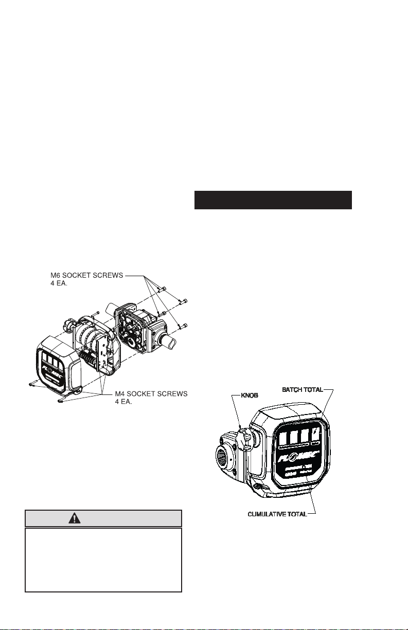
Changing Display Orientation
1� The mechanical display case can
be removed, rotated and reinstalled
for easy reading with either horizontal or vertical ow� (see Figure 2)
2� Using the 5mm hex L-wrench pro-
vided with the meter, remove the (4)
M6 socket screws that attach the
register case to the housing�
3� Without separating the mechanical
display from the housing, rotate to
desired orientation�
4� Reinstall the (4) M6 socket
screws and tighten to 42-46 lb-in
[4�7-5�2 N•m] torque�
Note: By first removing the (4) M4
socket screws and top cover, better
interior viewing can be achieved� This
is not a mandatory step though�
2� Wrap threaded male connections
with thread tape or use a pipe
sealant compound compatible with
petroleum fuels�
3� Install the meter on the pump us-
ing an appropriately sized nipple�
The bottom of the meter housing
is embossed with “INLET” and
“OUTLET” adjacent to its respective port to assist in correct piping
connections�
4� Install other system components
onto the meter and tighten�
OPERATION
ALWAYS FOLLOW SAFETY PRECAUTIONS
WHEN OPERATING THIS EQUIPMENT. REVIEW
THE SAFETY INSTRUCTIONS. Before each
use, visually check the meter to ensure
it is securely connected to other system
components and there is no leakage�
Promptly wipe spilled fuel from the
meter’s exterior and other system
components�
The large meter display represents
the Batch Total for each fuel delivery�
Before dispensing, reset the Batch
Total to zero by turning the knob� (see
Figure 3)
gure 2
Meter Installation
1� Remove the protective plugs from
the meter inlet and outlet ports� The
inlet port has a 100 mesh stainless
steel conical strainer installed�
CAUTION
The mesh strainer must always be
installed when operating the meter;
otherwise, particles may enter the
meter chamber and disrupt the
smooth operation of the oval gears�
4
gure 3
The small display represents the
Cumulative Total of all fuel deliveries
and cannot be reset�
Page 5
CALIBRATION
The meter is accurately calibrated at the
factory for use with diesel fuel� Due to
differences in viscosity and ow rates,
the meter may require recalibration
to measure other fuels or to adjust
for inaccuracies� A gear replacement
kit is available (PN 139500-15, see
Illustrated Parts List section) to
convert the meter to unleaded fuels�
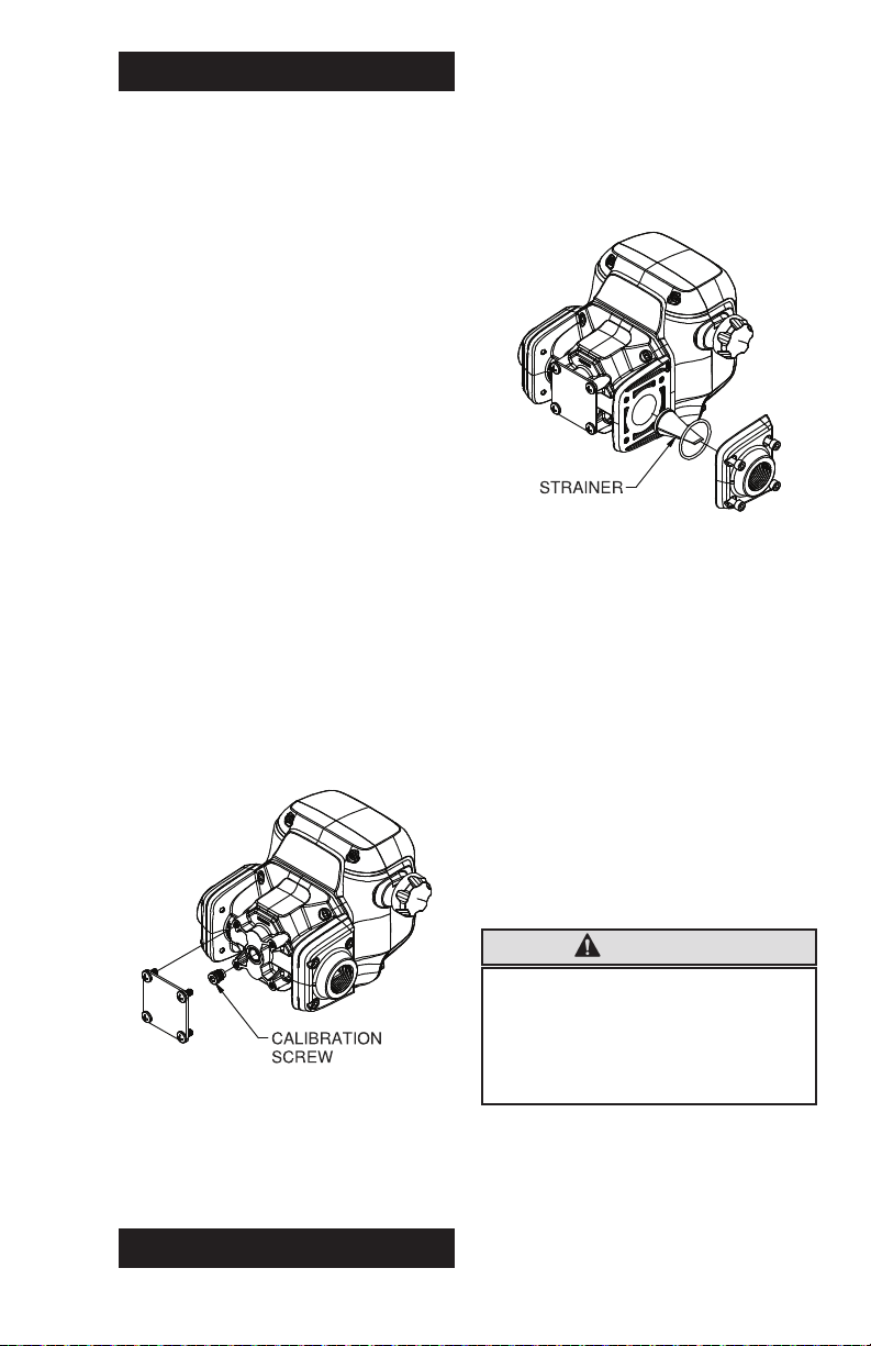
1� To adjust the calibration of the me-
ter, gain access to the calibration
screw by performing the following:
(see Figure 4)
2� Remove the back plate and the
(4) screws retaining it� The O-ring
seal under the plate must not be
damaged�
3� Using the 5MM hex L-wrench
provided with the meter, adjust the
calibration screw as required�
4� Note: The calibration screw set-
ting may have been adjusted at
the factory� The gasoline setting
is approximately fully closed (turn
clockwise)� Do not overtighten the
screw against the seat�
at regular intervals, especially if reduced
ow is encountered�
Clean or Replace Strainer
1� Remove the socket screws at the
inlet tting� Remove the tting, Oring and strainer� (see Figure 5)
gure 5
2� The strainer rim is pressed into the
housing inlet but can be removed
by carefully grasping the end with
pliers and pulling with a wiggling
motion until free�
3� Using a ne brush, clean the strainer�
Replace the strainer as necessary�
4� Wipe the housing inlet clean and
reinstall strainer, pressing it into
the strainer bore� It is designed to
be eld pressed back into place
using the end of a clean 1” pipe
nipple or similar tube tool using light
hammer taps�
gure 4
5� Reinstall the plate, (4) screws
and the O-ring seal if removed�
Tighten (4) screws to 42-46 lb-in
[4�7-5�2 N•m] torque�
MAINTENANCE
The meter’s strainer should be cleaned
CAUTION
The mesh strainer must always be
installed when operating the meter;
otherwise, particles may enter the
meter chamber and disrupt the
smooth operation of the oval gears�
5� Wipe clean the tting and O-ring
groove� Coat the O-ring with oil or
light grease and seat into the tting
groove�
6� Reinstall the inlet tting and screws�
Tighten screws to 42-46 lb-in
[4�7-5�2 N•m] torque�
5
Page 6

TROUBLESHOOTING
Symptom Probable Cause Corrective Action
A� Meter counter does
not operate� (Normal
fuel ow)
B� Meter counter does
not operate�
(Little or no fuel ow)
C� Fuel leakage� Leakage between
Broken counter
Replace counter�
assembly�
Counter alignment Look for loose or
missing fasteners, bent
or misaligned parts�
Foreign material in
counter assembly�
Missing or worn bevel
Remove and clean
counter assembly�
Replace bevel gear�
gear�
Clogged strainer in
meter inlet�
Jammed rotors from
foreign material in rotor
Clean or replace
strainer
Remove and clean rotor
assembly�
assembly�
Other system
components
malfunctioning�
Check all system
components tank to
nozzle for clogs and/or
malfunctions� Repair as
necessary�
Remove coverplate and
coverplate and housing�
inspect for damaged,
missing or incorrectly
seated seal� Replace
as required�
Leakage at ttings Remove ttings and
inspect for damaged,
missing or incorrectly
seated seals� Replace
as required�
Leakage at threads� Remove meter and
reseal all threaded
connections with thread
tape or pipe thread
sealing compound
approved for use with
ammable liquids�
6
Page 7

SPECIFICATIONS
Gallon Models Litre Models
Model
Designation
Unit of Measure U�S� Gallon Litre
Flow Range 2 to 40 GPM 8 to 150 LPM
Typical Accuracy
(Factory Set)
Typical Accuracy
(Field/Customer
1
Set)
1
Diesel: ±0�25% at a given flow (15-30 GPM/57-113 LPM)
Unleaded: ±0�5% at a given flow (2-23 GPM/8-87 LPM)
Resolutional
Error (Display)
Operating
Temperature
Maximum Working Pressure
Wetted Materials:
Housing / Cover
/ Fittings
Rotors PPS (Polyphenylene Sulde)
Shafts / Strainer Stainless Steel
Seals NBR (Nitrile Butadiene Rubber)
Mag-Drive Acetal, Stainless Steel and Neodymium (Nickel Plated)
Inlet/Outlet Ports 1" NPT (female) 1" NPT (female)
Pressure Drop
(at Max� Flow)
Maximum
Batch Total
Maximum
Cumulative Total
Technology Positive Displacement
QM240N QM150N
Diesel: ±0�5% (15-30 GPM/57-113 LPM)
±1�0% all other flowrates
Unleaded: +0�5% to -1�5% (15-30 GPM/57-113 LPM)
±2�0% all other flowrates
±0�5% all other given flows
±0�5% at a given flow (23-40 GPM/87-150 LPM)2
(0�01/Dispensed
Amount)*100
(0�1/Dispensed
Amount)*100
-20°F to 125°F -29°C to 52°C
50 PSIG / 3�4 Bar
Aluminum
Diesel: 7�0 PSI / 0�5 Bar
Unleaded: 4�5 PSI / 0�3 Bar
999�9 9999
9,999,999�9 99,999,999
1
Results may vary due to application variations�
2
Unleaded Fuel Kit required (Part No� 139500-15)
Note: Field Calibration is available on all models.
7
Page 8

PRESSURE DROP PSI
0
1
2
3
4
5
6
7
8
FLOWRATE GPM
FACTORY SETTING NOMINAL UPPER RANGE FACTORY SETTING NOMINAL LOWER RANGE
QM240 ACCURACY & PRESSURE DROP vs FLOWRATE - DIESEL
0 5 10 15 20 25 30 35 40
1.5
1.0
0.5
0.0
-0.5
ERROR %
-1.0
-1.5
CALIBRATION SCREW IN CALIBRATION SCREW OUT 2 TURNS PRESSURE DROP
8
Page 9

PRESSURE DROP PSI
0
0.5
1
1.5
2
2.5
3
3.5
4
4.5
5
FLOWRATE GPM
QM240 ACCURACY & PRESSURE DROP vs FLOWRATE - UNLEADED
SCREW IN ORIGINAL EQUIPMENT SCREW IN WITH GEAR KIT SC REW OUT 2 TURNS WITH GEAR KIT PRESSURE DROP
0 5 10 15 20 25 30 35 40
2.0
1.5
1.0
0.5
0.0
ERROR %
-0.5
-1.0
-1.5
*A gear replacement kit is available (P/N 139500-15) to convert the meter to unleaded fuels. Replacement gear kit will adjust entire ow curve up 1.5%.
9
Page 10

E
K
L
A
B
C
B
C
F
G
H
I
J
N
ILLUSTRATED PARTS LIST
10
Page 11

Includes (1) calibration screw, (1) O-
ring
Includes (1) back plate, (1) O-ring, at-
taching hardware
Includes (1) strainer
Not shown
I 139500-09 KIT, CALIBRATION SCREW:
J 139500-10 KIT, BACK PLATE:
- 139500-15 KIT, UNLEADED FUEL, QM240:
N 139500-14 KIT, STRAINER:
ITEM PART NO. DESCRIPTION
Includes (1) housing O-ring, (2) tting
O-rings, (1) back plate O-ring
Includes (2) ttings, (2) tting O-rings,
(1) strainer, attaching hardware
Includes (2) ttings, (2) tting O-rings,
(1) strainer, attaching hardware
Includes (1) rotor set
Includes (1) assembled coverplate
(gears, mag drives), housing seal, at-
taching hardware
Includes (1) assembled coverplate
(gears, mag drives), housing seal, at-
taching hardware
A 139500-01 KIT, SEAL:
ITEM PART NO. DESCRIPTION
Kits and Accessories
B 139500-02 KIT, FITTING, 1” NPT:
C 139500-03 KIT, FITTING, 1” BSPP:
F 139500-06 KIT, ROTOR:
G 139500-07 KIT, COVERPLATE ASSEMBLY, GAL:
H 139500-08 KIT, COVERPLATE ASSEMBLY, LITRE:
11
Page 12

D
E
K
L
M
H
ILLUSTRATED PARTS LIST
12
Page 13

Includes (1) knob assembly
Includes (1) counter assembly, attach-
ing hardware
Includes (1) top cover w/gallon decal,
attaching hardware
Includes (1) top cover w/litre decal,
attaching hardware
Includes (1) middle cover, attaching
hardware
Not shown
E 139500-05 KIT, COUNTER ASSEMBLY:
D 139500-04 KIT, KNOB ASSEMBLY:
ITEM PART NO. DESCRIPTION
Kits and Accessories
K 139500-11 KIT, TOP COVER, GALLON:
L 139500-12 KIT, TOP COVER, LITRE:
M 139500-13 KIT, MIDDLE COVER:
- 139500-15 KIT, UNLEADED FUEL, QM240:
13
Page 14

14
Page 15

PARTS AND SERVICE
For warranty consideration, parts,
or other service information, contact
your local distributor� If you need
further assistance, please contact
GPI Customer Service Department
in Wichita, Kansas during normal
business hours at:
1-800-835-0113�
To obtain prompt, efficient service,
always be prepared with 1�) the model
number of your meter, 2�) the manufacturing date located on the back of the
meter, and 3�) specic information, as
necessary, obtained from the Illustrated
Parts List� For warranty work always be
prepared with proof of purchase date�
Please contact GPI before returning any
parts� It may be possible to diagnose
the trouble and identify needed parts
without returning parts� GPI can also
inform you of any special handling
requirements you will need to follow
covering the transportation and handling of fuel transfer equipment� Before
packing for shipment, make sure the
meter is thoroughly drained and free
of fuel and vapors�
CAUTION
Do not return meters or parts
without specic authority from the
GPI Customer Service Department�
Due to strict regulations governing
shipment of ammable liquids,
meters may be refused and
returned to the sender if sent
without authorization�
15
Page 16

Limited Warranty Policy
Great Plains Industries, Inc. 5252 E. 36th Street North, Wichita, KS USA 67220-3205, hereby provides a limited
warranty against defects in material and workmanship on all products manufactured by Great Plains Industries,
Inc. This product includes a 4 year warranty from date of purchase as evidenced by the original sales receipt.
A 54 month warranty from product date of manufacture will apply in cases where the original sales receipt is
not available. Reference product labeling for the warranty expiration date based on 54 months from date of
manufacture. Manufacturer’s sole obligation under the foregoing warranties will be limited to either, at Manufacturer’s option, replacing or repairing defective Goods (subject to limitations hereinafter provided) or refunding
the purchase price for such Goods theretofore paid by the Buyer, and Buyer’s exclusive remedy for breach of
any such warranties will be enforcement of such obligations of Manufacturer. The warranty shall extend to the
purchaser of this product and to any person to whom such product is transferred during the warranty period.
This warranty shall not apply if:
A. theproducthasbeenalteredormodiedoutsidethewarrantor’sdulyappointedrepresentative;
B. the product has been subjected to neglect, misuse, abuse or damage or has been installed or
operated other than in accordance with the manufacturer’s operating instructions.
To make a claim against this warranty, contact the GPI Customer Service Department at 316-686-7361 or
800-835-0113. Or by mail at:
Great Plains Industries, Inc.
5252 E. 36th St. North
Wichita, KS, USA 67220-3205
GPI will step you through a product troubleshooting process to determine appropriate corrective actions.
GREAT PLAINS INDUSTRIES, INC., EXCLUDES LIABILITY UNDER THIS WARRANTY FOR DIRECT, INDIRECT, INCIDENTAL AND CONSEQUENTIAL DAMAGES INCURRED IN THE USE OR LOSS OF USE OF
THE PRODUCT WARRANTED HEREUNDER.
Thecompanyherewithexpresslydisclaimsanywarrantyofmerchantabilityortnessforanyparticularpurpose
other than for which it was designed.
ThiswarrantygivesyouspecicrightsandyoumayalsohaveotherrightswhichvaryfromU.S.statetoU.S.state.
Note: In compliance with MAGNUSON MOSS CONSUMER WARRANTY ACT – Part 702 (governs the resale
availability of the warranty terms).
Some models are not UL Listed.
Check your model for UL label if in doubt.
© 2019 GREAT PLAINS INDUSTRIES, INC. All Rights Reserved.
and FLOMEC are registered trademarks of Great Plains Industries, Inc.
04/2019 921528-01 Rev. D
 Loading...