

Flomec G Series Owner's Manual

921977-01C06/15
G SERIES TURBINES
(Industrial and Chemical Models)
Owner’s Manual
SAVE THESE INSTRUCTIONS

2 921977-01C
TABLE OF CONTENTS
General Information .............................2
Installation ...........................................3
Maintenance ........................................4
Troubleshooting .................................10
Specications ....................................13
Service...............................................15
To the owner…
Congratulations on receiving your
FLOMEC® G Series Turbine. We are
pleased to provide you with a product
designed to give you maximum reli-
ability and efciency.
Our business is the design, manufacture, and marketing of liquid handling,
agricultural, and recreational products. We succeed because we provide
customers with innovative, reliable,
safe, timely, and competitively-priced
products. We pride ourselves in conducting our business with integrity and
professionalism.
We are proud to provide you with a
quality product and the support you
need to obtain years of safe, dependable service.
President
Great Plains Industries, Inc.
GENERAL INFORMATION
This manual will assist you in installing and maintaining your FLOMEC G
Series Turbine. For best results, take
the time to fully acquaint yourself with
all information about all components of
your G Series Turbine. If you need assistance, contact the distributor from
whom you purchased your turbine.
Product Description
FLOMEC G Series Turbine owmeters are volumetric ow measurement
devices. The moving uid is used to
turn a rotor, which is suspended in
the ow stream. The rotating speed
of the rotor is proportional to the uid
velocity or owrate. As the blades from
a spinning rotor pass by a magnetic
sensor, an AC voltage pulse is generated and transmitted to the readout
instrument. Each pulse is equal to a
given volume of liquid, therefore “x”
number of pulses are equal to a gallon, litre, pound, barrel, etc.
Turbine Sizing
FLOMEC G Series Turbines are
identied by the internal diameter of
the inlet and outlet.
Model 050 ½ in. (0.6-6.0 gpm)
Model 051 ½ in. (0.8-6.0 gpm)
Model 075 ¾ in. (1.6-16 gpm)
Model 075E ¾ in. (2.3-23 gpm)
Model 100 1 in. (6.7-67 gpm)
Model 150 1½ in. (17.7-177 gpm)
Model 200 2 in. (33-330 gpm)
Model 300 3 in. (60-600 gpm)
Turbine owmeters should be sized
in accordance to the actual owrate
and not the process pipe size. For
example: a process having a owrate
of 10-20 GPM in a 1-½" process line
requires either a Model 075E or Model
100 turbine owmeter.
Another important factor to take into
consideration when sizing a turbine
owmeter is instantaneous owrate.

3
921977-01C
This is extremely important when
sizing a turbine owmeter where
the volume is measured per hour or
per day. For example, an application
where the total output is 500 barrels
per day, occurring in a 5 hour period;
the recommended turbine owmeter
should be sized according to the
instantaneous owrate:
(500 – 5) x 24 or 2,400 barrels per day
Thus, requiring an 1-½ inch turbine
owmeter.
INSTALLATION
Turbine owmeters are affected by
both upstream and downstream
process configurations. Turbine
owmeters should always be installed
with a minimum of 10 pipe diameters
upstream and 5 pipe diameters
downstream. The only exception is
the placement of the pumps, valves,
etc., on the upstream end. When this
occurs, 20 diameters of straight pipe
should be used. The direction of ow is
indicated by the arrow on the turbine.
All turbine owmeters are designed
to measure ow in only one direction.
Check the items below once the
turbine owmeter is installed in the
process line. This will ensure a successful start-up.
1. Before installing the magnetic sensor, make sure that it is functioning
properly. This can be accomplished
by checking the ohm resistance.
Refer to Checking Magnetic Pickup
in the Troubleshooting section.
2. If a magnetic pickup enclosure is
used on a sanitary turbine, discard
the seal cap that is included with the
unit. If no enclosure is used, install
the magnetic pickup and slip the
seal cap over the magnetic pickup
and threads on the adapter.
NOTE: This is not applicable for units
that use a low prole adapter.
3. Check the interconnection cable
between the turbine owmeter and
readout device. Refer to Checking
the Cable Assembly section.
4. Make sure that the new or correct
K-factor is entered into the readout
device.
Initial Start-Up
Turbine owmeters can be installed
in the horizontal or vertical position.
When installing a turbine owmeter
in the vertical position, it is important
that the direction of ow be up through
the turbine owmeter.
A spool should be installed in place
of the turbine owmeter during initial
start-up of a new process line. The
process line should be purged, thus
eliminating any solids contained in
the line. Once this is completed, the
spool can be removed and the turbine
owmeter installed.
Whenever possible, use 20 straight
pipe diameters upstream and down-
stream of the turbine owmeter. The
length of straight pipe upstream and
downstream of the turbine owmeter
can be reduced with the use of ow
straighteners or straightening vanes.
A minimum of 10 straight pipe diameters upstream and 5 downstream
are required.
NOTE: Control valves should always
be installed downstream of the
turbine owmeter.
The turbine owmeter should be
installed in a location where the process line will remain full of liquid at all
times. Otherwise, when the process
line becomes empty and a valve is
opened, the high velocity uid hitting
the turbine owmeter rotor can cause
severe damage.
When there is entrained air in the
process line, an air eliminator should
be used. This entrained air causes
air pockets and these air pockets
4 921977-01C
will cause the rotor to spin at a faster
rate than liquid, thus resulting in incorrect readings, which results in an
overstatement of actual owrate and
volume. This condition can damage
the owmeter.
In process lines where particulates
are present, a lter/strainer should
be used. Refer to the table below for
the recommended mesh size.
Turbine
Flowmeter Size
Mesh Size
½ inch 40
¾ inch 40
1 inch 40
1-½ inch 18
2 inch 14
3 inch 14
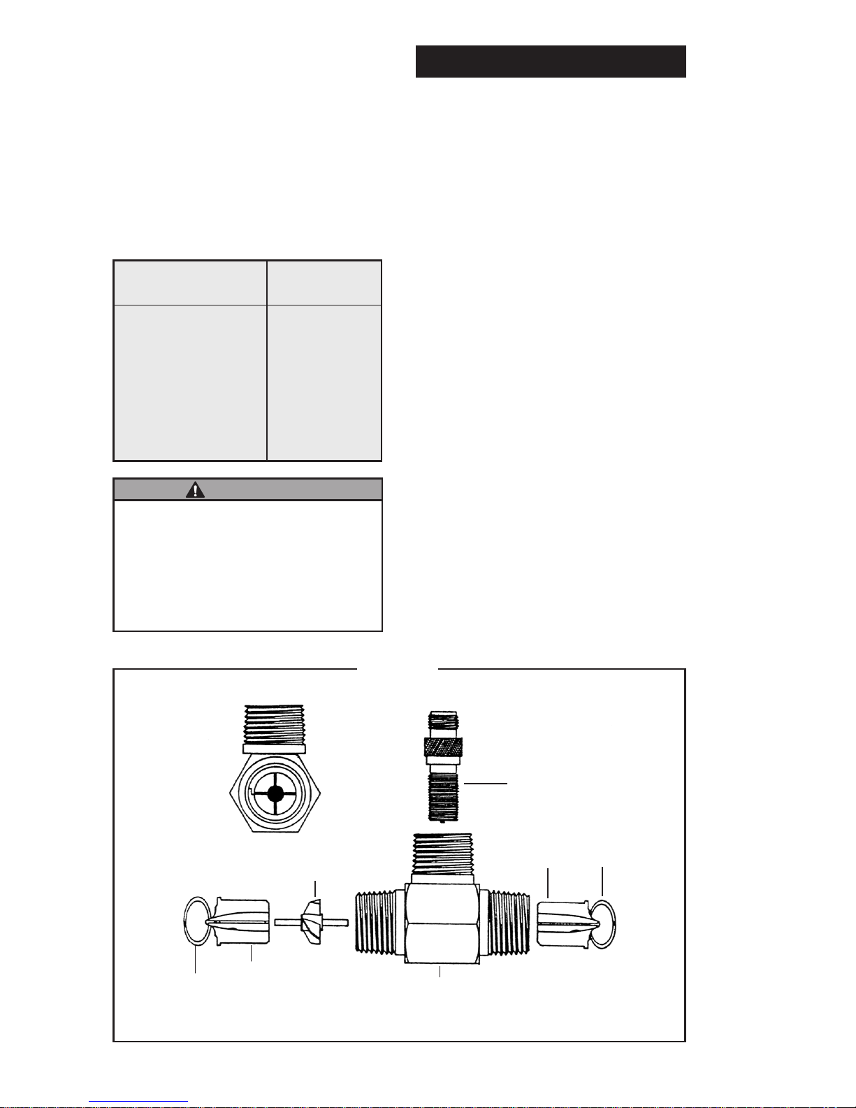
Figure 1
Contact the factory for sanitary versions of this meter.
MAGNETIC PICKUP
(HAND TIGHTEN ONLY)
END VIEW
RETAINING
RING
ROTOR
SUPPORT
ROTOR
BODY
ROTOR
SUPPORT
RETAINING
RING
F L O W
➞
MAINTENANCE
Disassembling the Turbine
1. Disconnect the turbine owmeter
cable from the magnetic pickup.
Refer to Figure 1.
2. Remove the magnetic pickup.
3. Ensure that the process line is
depressurized and empty prior to
removal of the turbine owmeter.
Remove the turbine owmeter from
the process line.
4. Using a small screwdriver or similar
tool, insert it into the radius notch
of the retaining ring, pull away from
the groove and up, removing the
retaining ring from one end of the
turbine owmeter. This will allow
the support to slide out of the
turbine owmeter body. Remove
the rotor before proceeding to the
other support.
NOTE: To remove the other support,
simply repeat this operation.
If liquid being measured by
sleeved bearing turbine owmeters contains large solids, install a
lter or strainer. Without the use
of a lter or strainer, damage can
occur to the internal components.
WARNING

5
921977-01C
5. Once the turbine owmeter is taken
apart, inspect the turbine owmeter
body for signs of wear or defects.
The body bore should be smooth
and show no evidence of wear.
NOTE: Do not install a new replace-
ment kit into a turbine owmeter
body that shows signicant signs
of wear.
6. Examine the rotor for broken and/
or bent blades.
7. Examine the supports for signs of
deterioration, such as wear marks
and/or burrs along the outer edge
of the support vanes.
8. When the rotor or the supports
show any sign of deterioration,
a new replacement kit should
be installed. Do not install a new
replacement kit into a defective
turbine owmeter body.
Replacement Kits
A replacement kit is comprised of all
the internal component parts within
the turbine owmeter. A replacement
kit consists of the following:
Parts Description Quantity
Rotor Assembly 1
Support Assembly* 2
Retaining Ring 2
* The support assemblies come complete with bush-
ings and thrust balls, which are factory installed.
Proper selection of bearing material is critical when
ordering a new replacement kit.
FLOMEC® supports are identical in
design, thus eliminating assembly error. Each support incorporates a thrust
bearing, which allows for bidirectional
ow and prevents damage to the rotor
and/or supports in the event the tur-
bine owmeter is installed backwards
with respect to the direction of ow.
Notice that the direction of ow is
displayed on the body of the turbine
owmeter. This is important when
installing the rotor and also denotes
the direction in which the turbine
owmeter was calibrated.
NOTE: FLOMEC rotors are tapered on
one end (except ½" and ¾"). The
tapered end should be installed
on the inlet side. See Figure 1.
The ½" and ¾" rotors are marked
with a point on the hub and should
be installed with the marked side
of the rotor hub on the inlet side.
1. Install a support on the inlet side
(where the ow starts), placing a
vane between the notches in the
turbine owmeter body. Install a
retaining ring – this will keep the
support in place.
2. Place the rotor with the shaft in
the support that has not been in-
stalled. Hold the turbine owmeter
body with the open end down and
slide the rotor and support into the
turbine owmeter body. Make sure
the vane is placed between the
notches.
3. Once the support is in place, install
the retaining ring.
4. Blow into the turbine owmeter to
ensure the rotor spins freely.
Installation of the replacement kit is
complete and the turbine owmeter
can be reinstalled into the process line.
5. Install the magnetic pickup. HAND
TIGHTEN ONLY.
NOTE: Be sure to use the proper
magnetic pickup, cable and connector for the application.
6. Enter the new K-factor supplied
with the replacement kit into the
electronic readout device. (Refer
to the calibration report.)
NOTE: All internal replacement kits
are factory calibrated and are sup-
plied with a ve point calibration
certicate.
 Loading...