

Page 1

Reduced Pressure Zone Specification Submittal Sheet
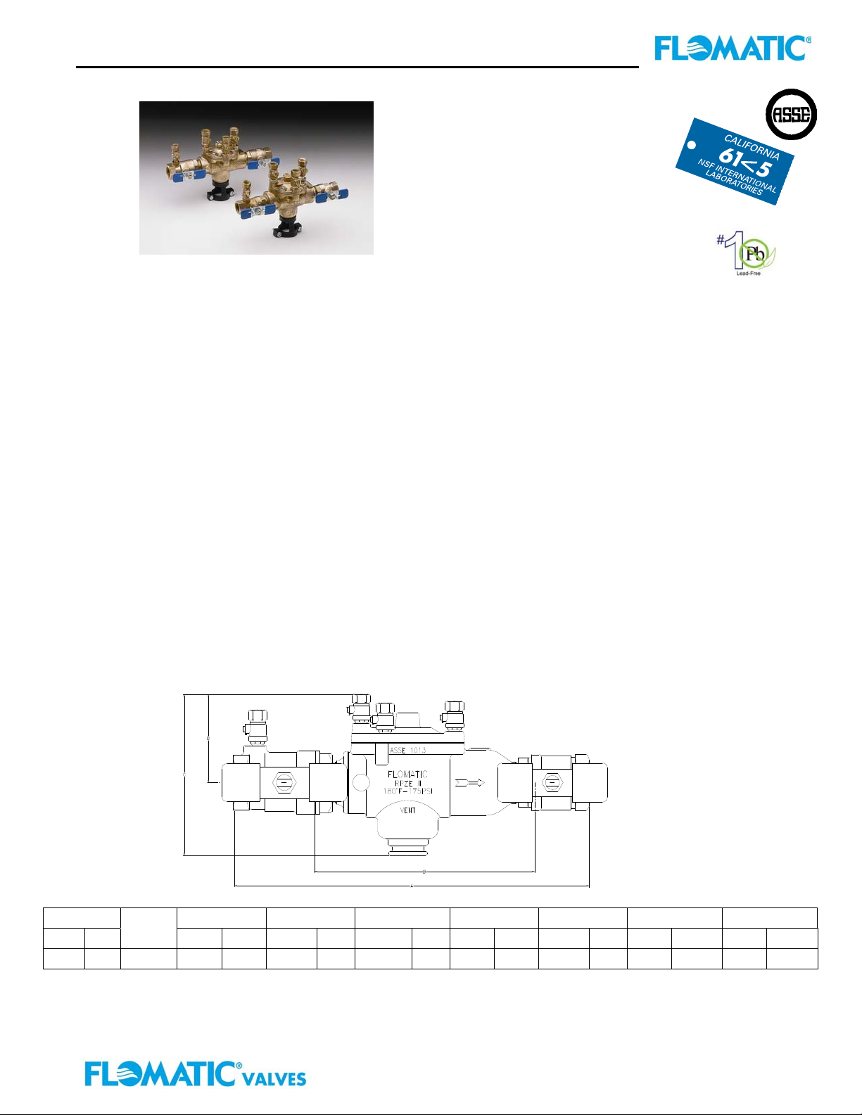
Model RPZE II (½” & ¾”)
FEATURES:
Sizes: □½” □¾”
Max. working pressure: 175 PSI (1200 kPa)
Max. working temperature: 180F (82C)
Hydrostatic Test Pressure: 350 PSI (2400 kPa)
MATERIALS:
Valve Body: Unleaded Bronze
Access Cover: Unleaded Bronze
Polymers: Noryl
Elastomers: Silicone
Springs: Stainless Steel
OPTIONS:
1 – less ball valves (ex B9310E replace 3
UE– with union end ball valves
S – with bronze “Y” type strainer
TM,
NSF Listed
rd
number)
STANDARDS COMPLAINCE:
● ASSE® Listed 1013
● CSA® Listed
● AWWA Compliant C511
● City of Los Angeles Approved
● Approved by the Foundation for Cross-Connection
Control and Hydraulic Research at the University
of Southern California
● LEAD PLUMBING LAW COMPLIANCE
.25% Max Weighted Average Lead Content
Certified by IAPMO R&T Lab
FLOMATIC SPECIFICATIONS:
Reduced Pressure Principle backflow preventer shall
protect against backflow by either backpressure or
backsiphonage from a cross-connection between
potable water systems and substances that are nonhealth and health hazards.
The device shall be ANSI 3rd party certified to comply
with states lead plumbing law and shall be constructed
from unleaded bronze with less than 0.05% lead
content. It shall consist of two (2) mechanically
independent, spring loaded, center stem guided check
valves. It shall also have a hydraulically dependent
differential pressure relief valve with the sensing
passage set in an integral cast unleaded bronze body,
with a single access cover. The assembly shall have
four (4) vertical test cocks and two shut off valves
which are quarter-turn, full-port, resilient seated and
ball type which are constructed with low lead material,
less than 0.25% lead content (ASTM C90500) or
approved equal.
The relief valve shall have removable stainless steel
seat ring. The check valves shall be held into place by
stainless steel clips and the check valve assemblies
shall be non-interchangeable with silicone discs.
Size A B C D Width Wgt with BV Wgt less BV
Inch mm
½
¾ 20 B9300E 9-3/4 248 5-1/2 140 5-21/32 144 3-5/8 92 3-5/32 80 5 2.25 3.25 1.5
Part #
15 B9399E 9-1/4 235 5-1/2 140 5-21/32 144 3-5/8 92 3-5/32 80 4.5 2 3.25 1.5
Inch mm Inch mm Inch mm Inch mm Inch mm lbs kg lbs kg
Flomatic Corporation
Flomatic Corporation, 15 Pruyn’s Island, Glens Falls, New York 12801
Phone: 518-761-9797 Fax: 518-761-9798 www.flomatic.com
November 17,2004 Rev. 6 (6/11)
Specification Sheet RPZEII
Page 2
Reduced Pressure Zone Specification Submittal Sheet
Model RPZE II (½” & ¾”)
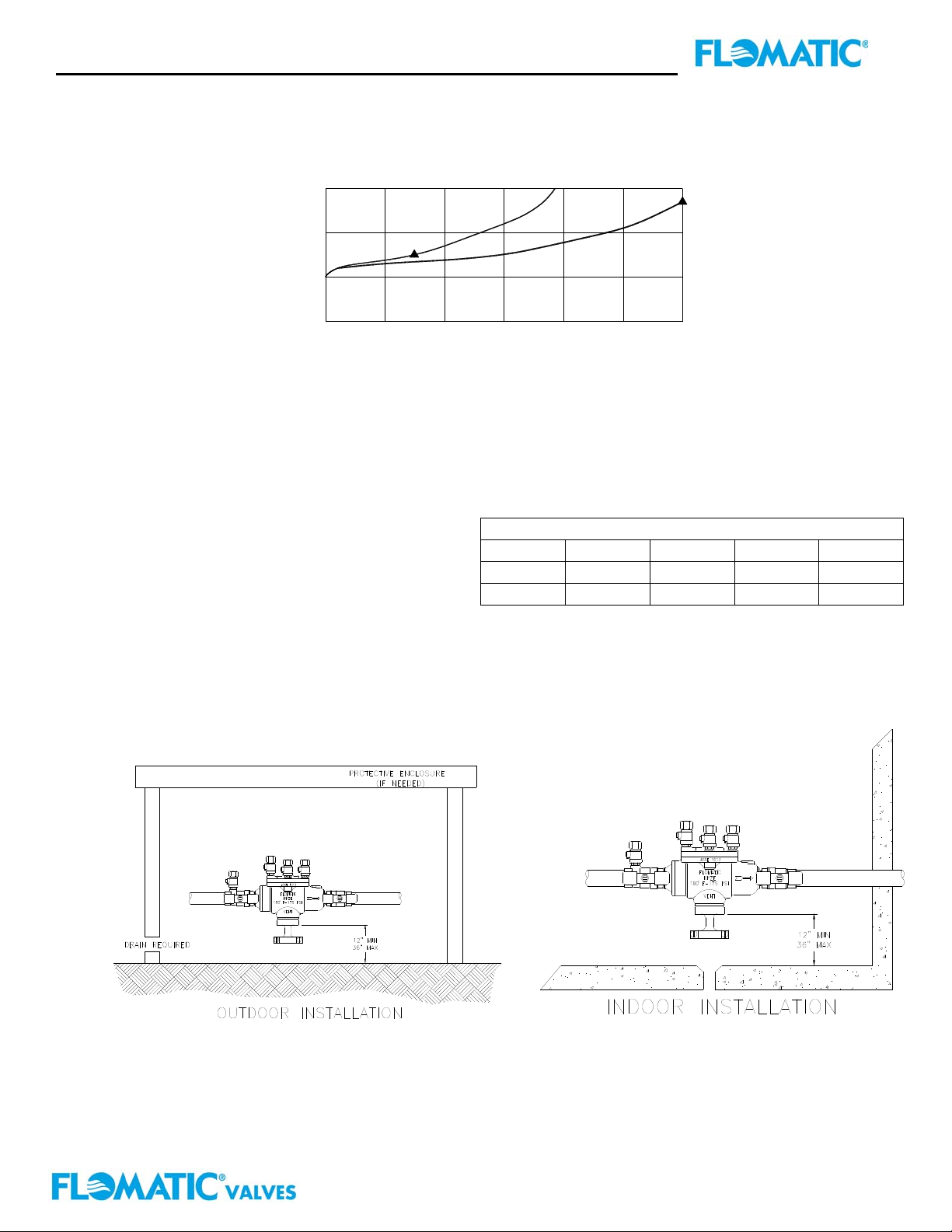
FLOW CHARACTERISTICS
i
a
s
P
p
k
138
20
S
S
O
103
15
L
E
R
U
S
69
10
S
E
R
P
35
5
0 10 20 30 gpm
FLOW CURVES w/ BALL VALVES
5
.32
(Established by Approval Agencies)
TYPICAL INSTALLATION
Model RPZE II Reduced Pressure Backflow
Preventers should be installed with adequate
clearance and easy accessibility for testing and
maintenance and must be
protected from freezing. Local codes shall govern
installation requirements. Unless otherwise specified,
the assembly shall be mounted at a minimum
clearance of 12” (305mm) between port and floor or
grade. The assembly shall have a maximum of 30”
(762mm) above adequate drains with sufficient side
clearance for testing and maintenance. The installation
shall be made so that no part of the unit can be
submerged. Thermal water expansion can cause
excessive pressure. Excessive pressure situations
should be eliminated to avoid possible damage to the
system and assembly.
WARRANTY: Flomatic valves are guaranteed against defects of materials or workmanship when used for the
services recommended. If in any recommended service, a defect develops due to material or workmanship, and the
device is returned, freight prepaid, to Flomatic Corporation within 12 months from the date of purchase, it will be
repaired or replaced free of charge. Flomatic Corporations’ liability shall be limited to our agreement to repair or
replace the valve only.
Flomatic Corporation, 15 Pruyn’s Island, Glens Falls, New York 12801
Phone: 518-761-9797 Fax: 518-761-9798 www.flomatic.com
1/2" & 3/4"
1/2" (15mm)
15
.95
FLOW RATE
▲ RATED FLOW
1.58
25
Capacity thru Schedule 40 Pipe (GPM)
Pipe size 5 ft/sec 7.5 ft/sec 10 ft/sec 15 ft/sec
½”
¾”
5 7 9 14
8 12 17 25
Flomatic Corporation
3/4" (20mm)
1.89 lps1.26.63
November 17,2004 Rev. 6 (6/11)
Specification Sheet RPZEII
Page 3
Reduced Pressure Zone Specification Submittal Sheet
Model RPZE II (1-½”)
FEATURES:
Sizes: □1½”
Max. working pressure: 175 PSI (1200 kPa)
Max. working temperature: 180F (82C)
Hydrostatic Test Pressure: 350 PSI (2400 kPa)
MATERIALS:
Valve Body: Unleaded Bronze
Access Cover: Unleaded Bronze
Polymers: Noryl
Elastomers: Silicone
Springs: Stainless Steel
OPTIONS:
1 – less ball valves (ex B9313E replace 3
UE– with union end ball valves
S – with bronze “Y” type strainer
TM,
NSF Listed
rd
number)
STANDARDS COMPLAINCE:
● ASSE® Listed 1013
● AWWA Compliant C511
● City of Los Angeles Approved
● LEAD PLUMBING LAW COMPLIANCE
.25% Max Weighted Average Lead Content
Certified by IAPMO R&T Lab
FLOMATIC SPECIFICATIONS:
Reduced Pressure Principle backflow preventer shall
protect against backflow by either backpressure or
backsiphonage from a cross-connection between
potable water systems and substances that are nonhealth and health hazards.
The device shall be ANSI 3rd party certified to comply
with states lead plumbing law and shall be constructed
from unleaded bronze with less than 0.05% lead
content. It shall consist of two (2) mechanically
independent, spring loaded, center stem guided check
valves. It shall also have a hydraulically dependent
differential pressure relief valve with the sensing
passage set in an integral cast unleaded bronze body,
with a single access cover. The assembly shall have
four (4) vertical test cocks and two shut off valves
which are quarter-turn, full-port, resilient seated and
ball type which are constructed with low lead material,
less than 0.25% lead content (ASTM C90500) or
approved equal.
The relief valve shall have removable stainless steel
seat ring. The check valves shall be held into place by
stainless steel clips and the check valve assemblies
shall be non-interchangeable with silicone discs.
Size A B C D Width Wgt with BV Wgt less BV
Inch mm
1-½
Part #
40 B9303E 17 432 10-1/2 267 4-1/2 114 8 203 5-1/8 130 18.5 8.5 12 5.5
Inch mm Inch mm Inch mm Inch mm Inch mm lbs kg lbs kg
Flomatic Corporation
Flomatic Corporation, 15 Pruyn’s Island, Glens Falls, New York 12801
Phone: 518-761-9797 Fax: 518-761-9798 www.flomatic.com
January 11,2010 Rev. 2 (6/11)
Specification Sheet RPZEII large
Page 4
Reduced Pressure Zone Specification Submittal Sheet
Model RPZE II (1-½”)
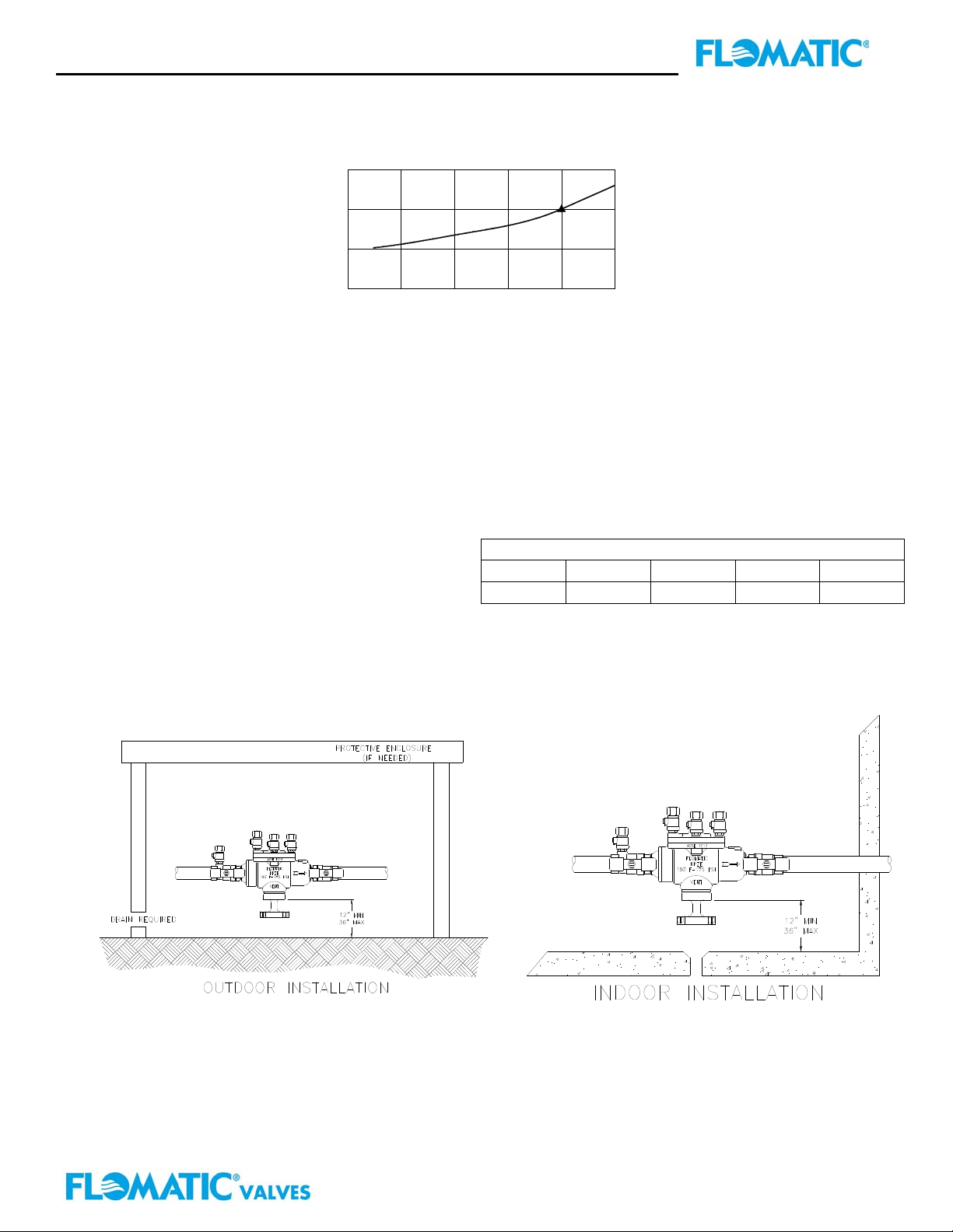
FLOW CHARACTERISTICS
P
k
138 20
S
S
O
103 15
L
E
R
U
S
S
E
R
P
35 5
i
a
s
p
1069
FLOW CURVES w/ BALL VALVES
0
1.58
25
(Established by Approval Agencies)
1-1/2"
1-1/2" (40mm)
3.15
7550
4.73
FLOW RATE
▲ RATED FLOW
6.31 7.89 lps
Flomatic Corporation
125 gpm100
TYPICAL INSTALLATION
Model RPZE II Reduced Pressure Backflow
Preventers should be installed with adequate
clearance and easy accessibility for testing and
maintenance and must be
protected from freezing. Local codes shall govern
installation requirements. Unless otherwise specified,
the assembly shall be mounted at a minimum
clearance of 12” (305mm) between port and floor or
grade. The assembly shall have a maximum of 30”
(762mm) above adequate drains with sufficient side
clearance for testing and maintenance. The installation
shall be made so that no part of the unit can be
submerged. Thermal water expansion can cause
excessive pressure. Excessive pressure situations
should be eliminated to avoid possible damage to the
system and assembly.
Pipe size 5 ft/sec 7.5 ft/sec 10 ft/sec 15 ft/sec
1 ½”
Capacity thru Schedule 40 Pipe (GPM)
32 48 63 95
WARRANTY: Flomatic valves are guaranteed against defects of materials or workmanship when used for the
services recommended. If in any recommended service, a defect develops due to material or workmanship, and the
device is returned, freight prepaid, to Flomatic Corporation within 12 months from the date of purchase, it will be
repaired or replaced free of charge. Flomatic Corporations’ liability shall be limited to our agreement to repair or
replace the valve only.
Flomatic Corporation, 15 Pruyn’s Island, Glens Falls, New York 12801
Phone: 518-761-9797 Fax: 518-761-9798 www.flomatic.com
January 11,2010 Rev. 2 (6/11)
Specification Sheet RPZEII large
 Loading...