

Page 1
Pressure Vacuum Breaker
Models PVB ¾“ &1”
Max Pressure – 175 PSI (12 BAR)
Max Temperature - 140ºF (60ºC)
Basic Installation Instructions
CAUTION: Installation of Backflow Preventers must be performed by qualified, licensed personnel.
Faulty installation could result in an improperly functioning device.
NOTE: CHECK WITH GOVERNING AUTHORITIES FOR LOCAL INSTALLATION REQUIREMENTS.
The installer should be sure the proper device has been selected for the particular installation.
The Danfoss Flomatic PVB contains an independently operating internally loaded check valve and an
independently operating loaded air inlet valve located on the discharge side of the check valve. When the
discharge pressure drops to 1 psi or below, the air vent opens and the spring loaded check valve closes the
valve inlet, preventing back-siphonage. During normal flow, the water opens the check valve assembly and
seat the vent disc holder against the bonnet as the body fills with water. The assembly is equipped with two
resilient-seat quarter turn shut-off valves and two test-cocks
The Danfoss Flomatic PVB is designer to prevent back-siphonage of contaminated water into the potable
water supply.
NOTE: Installations must have continuous pressure with no back pressure. For installations requiring
protection against backpressure install a Danfoss Flomatic RPZE or RPZE II.
Installation
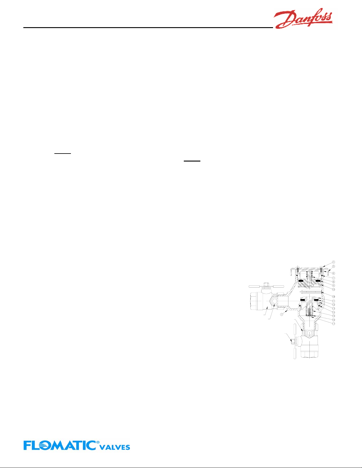
The Danfoss Flomatic Model PVB must be installed in a vertical position with the supply connected to the
bottom of the assembly, as shown above. The valve should be installed with adequate clearance on all sides
to allow for periodic inspection, testing, and maintenance. The Assembly must be installed at least 12" above
the highest downstream outlet. Do not install in a pit or vault. Protect the device from freezing. The
Assembly must not be installed where back pressure is present.
In case of possible warranty claim, contact your local supplier or Danfoss Flomatic representative. DO NOT
REMOVE ASSEMBLY FROM THE PIPELINE.
The assembly must be protected from freezing and excessive pressure increases. Pressure increases can
be caused by thermal expansion or water hammer. These excessive pressure situations must be eliminated
to protect the valve and the system from possible damage. For protection against water hammer shocks,
install a water hammer arrestor utilizing good plumbing practice.
Placing the Device in Service
After proper installation of a Danfoss Flomatic Model PVB, place the unit in service as follows:
1. Begin with both Shut Off Valves closed. Pressurize the system up to the Model PVB.
2. Open Shut Off Valve #1 completely. Some spillage may occur from the Canopy until the unit is
pressurized.
Note:
Do not install in an area where the spillage of water may cause damage or be objectionable.
Installation Instructions
Danfoss Flomatic
Danfoss Flomatic Corp, 15 Pruyn’s Island, Glens Falls, New York 12801
Phone: 518-761-9797 Fax: 518-761-9798 www.flomatic.com
Rev. 4 (7/09)
PVB
Page 2
Pressure Vacuum Breaker
Models PVB ¾“ &1”
3. Slowly open Shut Off Valve #2 to pressurize the downstream system. The Model PVB is now in service.
4. After the Model PVB has been properly installed and placed in service, the unit should be tested (See
Testing Procedures).
NOTE: Annual inspection, testing & cleaning of valves / system is required. This will help to insure
maximum life and proper function.
MAINTENANCE INSTRUCTIONS
1. Turn off the water supply to the Model PVB.
2. Release the pressure from the device.
3. Remove the Canopy Screws and Canopy.
4. Unscrew the bonnet from the body.
5. Remove spring clip (item 18) using needle nose pliers. Squeeze clip and disengage from side wall, then
remove. Note:
6. Unscrew the Check Valve Assembly from the body. Note:
hot water heater element wrench with the sides ground down will also work, consult factory for other tools.
A hot water heater element wrench with the sides ground down will also work. Consult factory for other
tools.
7. Clean and inspect all components thoroughly prior to reassembly.
8. Vent and Check Valve Silicone Disc are reversible.
9. Replace parts as needed and reassemble in reverse order.
Testing Procedures
Test No. 1 Air Inlet Opening Point
Purpose: To determine the pressure in the body when the air inlet valve opens.
Requirement: The air inlet valve shall open when the pressure in the body is no less than 1.0 psi above
atmospheric pressure, and the air inlet valve shall be fully open when the water drains from the body.
Steps:
a. Remove the Canopy.
b. Bleed water through both testcocks to eliminate foreign material.
c. Install appropriate fittings to testcocks.
d. Attach the high side hose of the differential pressure gage to
Testcock #2, slowly open Testcock #2, make sure the end of low hose
is level with Testcock #2.
e. Bleed air from the hose and gage by opening the high side bleed
needle valve. Close the high side bleed needle valve.
f. Close (outlet) Shut Off Valve #2, then close (inlet) Shut Off Valve #1.
g. Slowly open the high side bleed needle valve no more than one-
quarter (1/4) turn, being careful not to drop the differential pressure
reading of the gage too quickly. Record the differential pressure
reading of the gage when the air inlet valve opens, must be greater
then or equal to 1.0 psi.
h. Close Testcock #2.
i. Remove equipment.
j. Open Shut Off Valve #1.
Test No. 2 Check Valve Closing Point
Purpose: To determine the static pressure drop across the check valve.
Requirement: The static pressure drop across the check valve shall be at least 1.0 psi.
Starting July 1st 2005 on serial numbers P0001 and larger.
Installation Instructions
A 12 point 1-3/8" socket is recommended, a
Shut Off Valve #2
Testcock #2
Danfoss Flomatic
Testcock #1
Shut Off Valve #1
Danfoss Flomatic Corp, 15 Pruyn’s Island, Glens Falls, New York 12801
Phone: 518-761-9797 Fax: 518-761-9798 www.flomatic.com
Rev. 4 (7/09)
PVB
Page 3

Pressure Vacuum Breaker
Models PVB ¾“ &1”
Steps:
a. Attach high side hose of the differential pressure gage to Testcock #1, open Testcock #1.
b. Bleed all air from the hose and gage by opening high side bleed needle valve. Close high side bleed
needle valve.
c. Close Shut Off Valve #1 (Shut Off Valve #2 remains closed from Test #1).
d. Open Testcock #2. The water in the body will drain out through Testcock #2. When the flow of water
stops, the gage reading is the pressure drop across the check valve, must be greater then or equal to 1.0
psi.
e. Close both Testcocks.
f. Remove equipment.
g. Open Shut Off Valve #1, then Shut Off Valve #2.
h. Replace the Canopy.
TROUBLE SHOOTING GUIDE
Problem Possible Cause Solution
1. Check valve fails to
hold 1.0 psid minimum
2. Poppet fails to open
at 1.0 psig minimum
3. Minor leakage thru
air vent
4. Significant
discharge thru air vent
5. Chatter during flow
conditions
Winterization
1. Close main shut-off (1) to stop water supply to system.
2. Open the inlet (2) and outlet (6) drain valves, inlet (3) and outlet (5) shut-off valve on PVB and both
tescocks (4). All valves and testcocks must be left half open which is 45º to full open or close. This will
allow complete drainage.
A. Debris on sealing surfaces of valve
B. Damaged seat disc
C. Weak or broken spring
D. Poppet broken due to thermal expansion
A. Debris restricting free operation
B. Poppet seal adhering to bonnet
C. Weak spring load
A. Damaged poppet seal
B. Cracked or damaged poppet
C. Cracked bonnet or damaged sealing edge
D. Debris on sealing surface
A. Poppet not properly guided
B. Major poppet or seal failure
C. Low downstream pressure
D. Insufficient inlet volume to operate device
E. Poppet and/or bonnet broken
A. Worn, damaged or defective check valve
guide
Installation Instructions
Danfoss Flomatic
a. Disassemble and clean check
b. Disassemble & replace seal
c. Disassemble & replace spring
d. Replace broken poppet
a. Disassemble and clean check
b. Disassemble & clean or replace
damaged parts
c. Replace bonnet assembly
a. Disassemble & replace seal
b. Disassemble & replace poppet
seal
c. Disassemble & replace bonnet
seal
d. Disassemble & clean
a. Disassemble & clean or replace
damaged parts
b. Disassemble & clean or replace
damaged parts
c. Check pressure @ #2 testcock,
should be higher than 5 psig if low
system
d. Pressure needs to be increased
or partially closed outlet ball valve
to create higher pressure on
poppet
e. Replace broken bonnet/poppet
due to thermal expansion
a. Disassemble & repair or
replace guide
Danfoss Flomatic Corp, 15 Pruyn’s Island, Glens Falls, New York 12801
Phone: 518-761-9797 Fax: 518-761-9798 www.flomatic.com
Rev. 4 (7/09)
PVB
Page 4

Pressure Vacuum Breaker
Models PVB ¾“ &1”
3. Blowing out the system downstream will require the outlet drain valve (6) to be opened and the PVB outlet
shut-off valve (5) to be closed.
4. Attach air hose to the outlet drain valve (6), turn on air and make sure all water is removed from the
downstream part of system.
5. WARNING: Make sure to put the PVB outlet shut-off valve (5) and outlet drain valve (6) back to the 45º
open position after blowing open is completed.
6. If drain valves (2&6) are NOT part of your system and/or air is not used to blow out the system, make sure
to remove the PVB internal components for the winter.
7. WARNING: Make sure the resilient seated main shut-off valve (1) is completely shut and remains so to
prevent water from refilling the system causing damage.
Installation Instructions
Danfoss Flomatic
3 Year Limited Warranty
All products manufactured & sold by Danfoss Flomatic carry with them the following warranty: Danfoss Flomatic
warrants to the original purchaser (end user) all products manufactured by it will be free from defects in workmanship &
material for a period of three (3) years.
This warranty is applicable provided such products are used under normal conditions within the recognized pressure,
flow & temperature limits & are given normal service & care. DANFOSS FLOMATIC MAKES NO OTHER
REPRESENTATION OR WARRANTY OF ANY KIND EXPRESSED OR IMPLIED, IN FACT OR IN LAW, & EXPRESSLY
DISCLAIMS ALL OTHER WARRANTIES, INCLUDING WITHOUT LIMITATION, THE WARRANTIES OF
MERCHANTABILITY OR FITNESS FOR PARTICULAR PURPOSE. In the event of a defect in material or workmanship
of a product covered by this warranty, Danfoss Flomatic shall at its solo option, repair or replace such defective product.
Danfoss Flomatic shall not be liable for any labor required to repair or replace any product covered by this warranty. This
warranty is void with respect to any such product which is altered or tampered with by anyone without prior consent of
Danfoss Flomatic. Danfoss Flomatic shall not be liable under any circumstances for damages caused by accident,
misuse or abuse of the product or for failure to follow the installation, maintenance or operating instructions. IN NO
EVENT SHALL DANFOSS FLOMATIC BE LIABLE FOR INCIDENTAL, INDIRECT, PERSONAL INJURY, PROPERTY
OR PUNITIVE DAMAGES.
To make a claim under this warranty, the buyer must notify the factory in writing within ten (10) days of discovery of any
claimed defects or workmanship, & if authorized by the factory, shall return the product in the same condition as when
received by the buyer, transportation prepaid, to the factory or to such other location as directed by the factory. If said
returned product is found by the factory to be defective in workmanship or materials, it shall be repaired or replaced
without charge, pursuant to the terms of this warranty. This warranty excludes component parts or appurtenances not
manufactured by Danfoss Flomatic. Any claims with respect to such equipment must be made to the manufacturer in
accordance with the terms of the warranty, if any, given by such manufacturer, or pursuant to such warranties as may
exist by law. The physical or chemical properties of Danfoss Flomatic products represent typical, average values
obtained in accordance with test methods & are subject to normal manufacturing variations. This information is supplied
as a technical service and is subject to change without notice.
Danfoss Flomatic Corp, 15 Pruyn’s Island, Glens Falls, New York 12801
Phone: 518-761-9797 Fax: 518-761-9798 www.flomatic.com
PVB
Rev. 4 (7/09)
 Loading...