

Page 1
Pilot Valves Installation Instructions
Model PRP ⅜”
Description:
The PRP Pressure Reducing Pilot Control Valve automatically reduces a higher inlet pressure
to a lower outlet pressure. It is a direct acting, spring-loaded, diaphragm type valve that operates hydraulically and is
designed to maintain a pre-set pressure. When used as a pilot control with a Flomatic Automatic Control Valve, it will
hold a constant downstream pressure at a pre-set pressure. See cross section drawing on back page.
Operation:
The PRP valve is normally held open by the force of the compression spring above the diaphragm; delivery pressure
acts on the diaphragm. The flow thru the valve responds to changes in the down stream pressure.
Installation:
Installation must be performed by qualified, licensed personnel only.
The PRP Valve may be installed in any position. There is one 3/8” NPT inlet port (sensing port) and one 3/8” outlets
(two ports optional), for either straight or angle installation. The second outlet port can be used for a gauge connection
(1/4” NPT optional, add GP to part number). A flow arrow is marked on the body casting.
Adjustment Procedure:
The PRP Valve can be adjusted to provide a delivery pressure range as specified on the data plate (25-175 PSI
standard range other spring ranges are available).
Pressure adjustment is made by turning the adjustment screw (first remove plastic protective cap and loosen
jam nut on adjustment screw) to vary the spring pressure on the diaphragm. The greater the compression on
the spring the higher the pressure setting.
1. Turn the adjustment screw in (clockwise) to increase delivery pressure.
2. Turn the adjustment screw out (counter-clockwise) to decrease the delivery pressure. When pressure
adjustment is completed, tighten jam nut on adjustment screw and replace protective cap.
For best operation, observes the minimum flow rates given in the table are for the main valve on which the PRP is
installed:
Maintenance:
Annual inspection and maintenance is required of all plumbing system components. To ensure proper performance and
maximum life, the PRP must be inspected, tested and cleaned on a regular basis.
Disassembly:
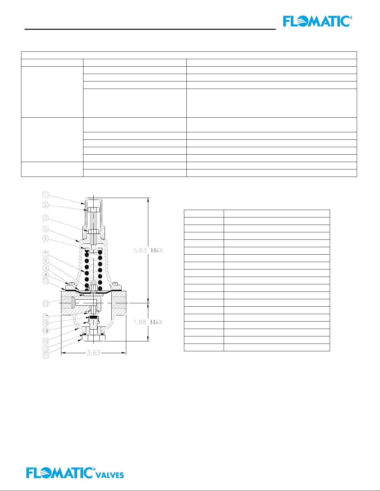
To disassemble follow the sequence of the item numbers assigned to parts on the cross section drawing on the reverse
side of this sheet.
Reassembly:
Reassembly is the reverse of the disassembly. Caution must be taken to avoid having the yoke (15) drag on the inlet
nozzle of the body (18). Follow this procedure:
1. Place yoke (15) in body and screw the disc retainer assembly (14) until it bottoms.
2. Install o’ring (12) onto body plug (11) and screw into body (16). Disc retainers must enter guide hole in
plug as it is assembled. Screw the body plug (16) in by hand. Use wrench to tighten only.
3. Place diaphragm (10) and diaphragm plate (9) on yoke (15). Screw on diaphragm nut (8) finger tight.
4. Aligned the diaphragm holes to the valve body screw holes before tightening of diaphragm nut (8) with
the yoke centered on valve seat. Pull yoke to open and lower yoke closed positions with no evidence of
yoke contacting or dragging valve body.
Important: Check for proper yoke/diaphragm alignment. Rotate diaphragm clockwise and then counterclockwise
as far as possible. Diaphragm holes should rotate equal distance on either side of valve body screw holes ±1/8”.
5. Install spring (7) place spring button (6) on top of spring.
6. Install cover (5), adjusting screw (2) with jam nut (3) using eight machine screws (4).
7. Attach black plastic adjustment cap (1) hand tight and lock in position with a fine wire to prevent
tampering with pressure setting.
Control Valve Size 1-1/4” thru 3” 4” thru 8” 10” thru 16”
Minimum Flow GPM 15-30 50-200 300-650
Flomatic Corporation
Flomatic Corp, 15 Pruyn’s Island, Glens Falls, New York 12801
Phone: 518-761-9797 Fax: 518-761-9798 www.flomatic.com
PRP
Rev. E
Page 2
Pilot Valves Installation Instructions
Model PRP ⅜”
Trouble Shooting Guide
Problem: Possible Cause: Possible Solutions:
Fails to regulate a
higher pressure
when pressure
lowers.
Fails to regulate a
lower pressure
when delivery
pressure rises
Leakage from
cover or vent hole
Information needed to order repair parts:
Pilot Model
Pilot Working Pressure
Limited One Year Warranty: Flomatic valves are guaranteed against defects of material or workmanship when used
for the services recommended. If, in any recommended service a defect develops due to material or workmanship, and
the device is returned, freight prepaid, to Flomatic Corporation within 12 months from date of purchase, it will be
repaired or replaced free of charge. Flomatic Corporations’ liability shall be limited to our agreement to repair or
replacement of valve only.
No spring compression. Tighten adjusting screw to give higher discharge pressure.
Damaged spring Disassemble & replace spring.
Spring button (6) is not in place Disassemble & place spring button (6) on top of spring (7).
Yoke dragging on sides of inlet
nozzle
Spring is too compressed Back off adjusting screw to give a lower discharge
Mechanical seat area obstruction Disassemble & remove foreign material obstruction.
Worn disc Disassemble, remove & replace disc retainer (14).
Yoke dragging on inlet nozzle Refer to paragraph 6
Damaged diaphragm (10) Disassemble & replace
Loose diaphragm nut (8) Remove cover & tighten diaphragm nut (8)
Damaged Diaphragm Disassemble PRP unit & replace diaphragm
Check for proper yoke/diaphragm alignment. Rotate
diaphragm clockwise & then counterclockwise as far as
possible. Diaphragm holes should rotate equal distance
on either side of valve body screw holes ±1/8”.
pressure.
Item # Description:
1 Adjustment Cap
2 Adjustment Screw
3 Jam Nut
4 Screw
5 Cover
6 Spring Button
7 Spring
8 Diaphragm Nut
9 Diaphragm Plate
10 Diaphragm
11 Body Plug
12 O’Ring
13 Pipe Plug (optional / not shown)
14 Disc Retainer
15 Yoke
16 Body
17 Seat
18 Disc
Flomatic Corporation
Flomatic Corp, 15 Pruyn’s Island, Glens Falls, New York 12801
Phone: 518-761-9797 Fax: 518-761-9798 www.flomatic.com
PRP
Rev. E
 Loading...