

Page 1
O&M Manual
®
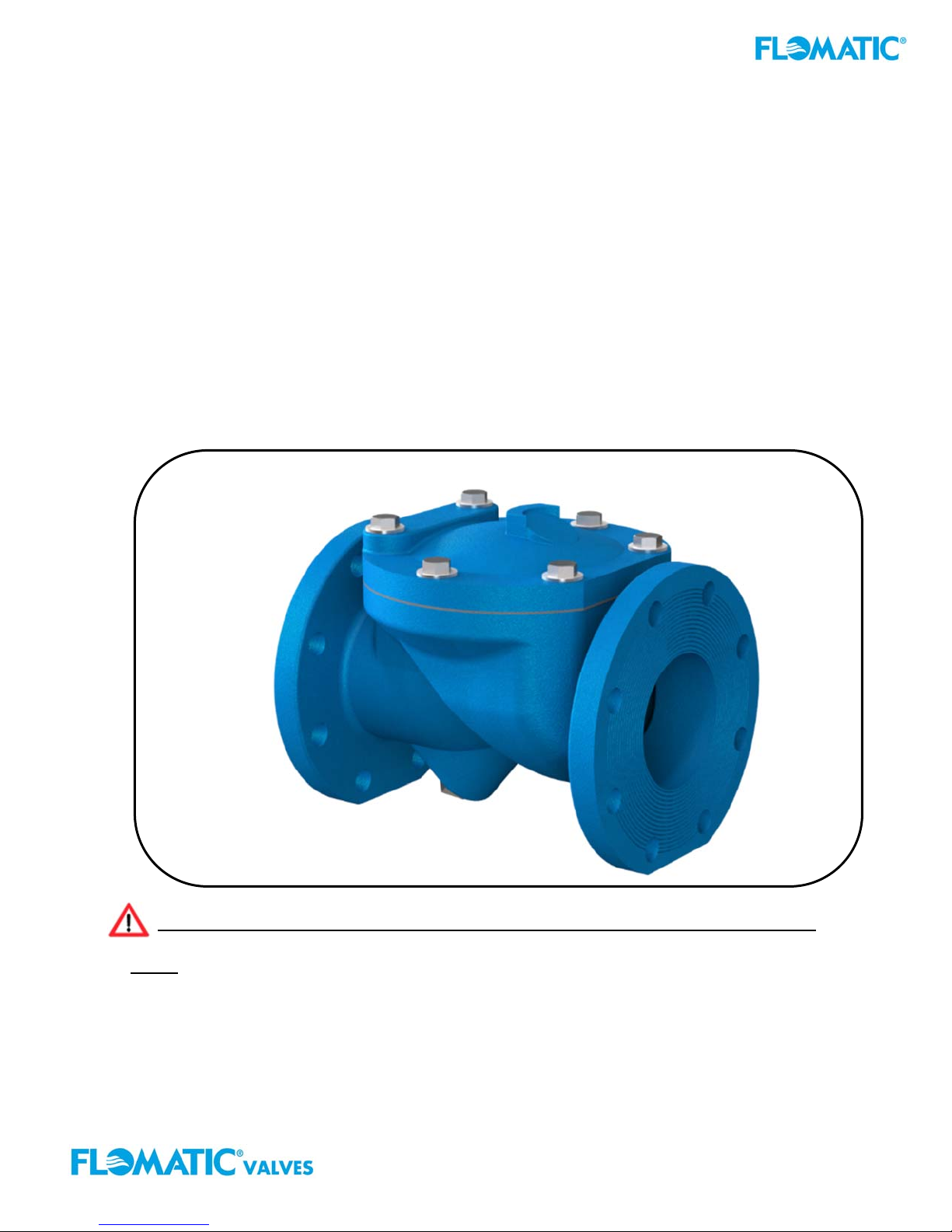
Flo-Flex
Swing Check Valve
Model 745
Operation, Maintenance and
Installation Manual
FAILURE TO FOLLOW THESE INSTRUCTION WILL VOID ANY WARRANTY
Note: Keep this O&M Manual in a safe place for future reference for service and parts.
Model: _________________ Size: ____________ Type: _________________
Working Pressure: __________ Installation Date: __________
Flomatic Corp, 15 Pruyn’s Island, Glens Falls, New York 12801
Phone: 518-761-9797 Fax: 518-761-9798 www.flomatic.com
745PI-BF-LS-ASC Rev. B
October 12, 2018
Page 2
Flo-Flex®Swing Check Valve
Model 745
Operation, Maintenance and
Installation Manual
List of Contents: Page:
INTRODUCTION 3
RECEIVING AND STORAGE 3
DESCRIPTION OF OPERATION 3
VALVE CONSTRUCTION 3
INSTALLATION 4
MAINTENANCE 4
TROUBLESHOOTING 4
DISASSEMBLY and RE-ASSEMBLY 4
BACK-FLUSH DEVICE (“BF” OPTIONAL) 5
POSITION INDICATOR (“PI” OPTIONAL) 6
LIMIT SWITCH (“LS” OPTIONAL) 6
SPARE PARTS AND SERVICE 7
WARRANTY 7
Flomatic Corp, 15 Pruyn’s Island, Glens Falls, New York 12801
Phone: 518-761-9797 Fax: 518-761-9798 www.flomatic.com
745PI-BF-LS-ASC Rev. B
October 12, 2018
Page 3
FLOMATIC'S® FLO-FLEX
®
Swing Check Valve
Operation, Maintenance and Installation Manual
INTRODUCTION
The Flomatic® Flo-Flex® Model 745 Swing Check Valve has been designed to give years
of trouble-free operation during normal operation. This O&M owners’ manual will
provide you with the information you need to properly install and maintain the valve and
to ensure a long service life. The Flo-Flex
®
check valve is opened automatically by the
fluid flow in one direction and closes automatically to prevent back-flow in the reverse
direction (see flow arrow cast into the valve body for flow direction). The Flo-Flex®
Model 745 swing check is design to meet the flange to flange laying length
according to AWWA C508. The valve angled valve seat and fully encapsulated,
resilient disc, is capable of handling a wide range of fluids including flows
containing suspended solids.
Flomatic
®
can provide an optional manual back-flush device that can be installed
StandardMaxWorkingPressure:
2”thru24”250psi
StandardMaxTemperature:
140°F(60°C)
on the bottom of the valve to allow manual backflow through the valve in the
reverse direction (Option Model 745 “BF”). Optional Position Indicators (Option Model 745 “PI”) PI and Limit Switches
(Option Model 745 “LS”) may also be mounted on the valve access cover to provide position indication.
The Valve Size, Flow Direction, Maximum Working Pressure are cast on to the side of the valve body surface for
reference. The "Maximum Working Pressure" is the non-shock pressure rating of the valve at “Max Temperature”
of 140°F (60°C). The valve shall not be subjected to any higher pressure or temperature above the valve
maximum standard rating.
RECEIVING AND STORAGE
Inspect valves upon receipt for damage in shipment. Unload valve carefully to the ground without dropping. Do not allow
lifting slings or chains to come in contact with the seat or flange sealing surface area; use eyebolts or rods through the
flange holes on large valves. Valves should remain crated, clean and dry until installed to prevent weather related damage.
For long term storage greater than six months, the rubber surfaces of the disc should be coated with a thin film of FDA
approved grease such as “Super Lube”. Do not expose disc to sunlight or ozone for any extended period as elastomer will
get damaged and degraded.
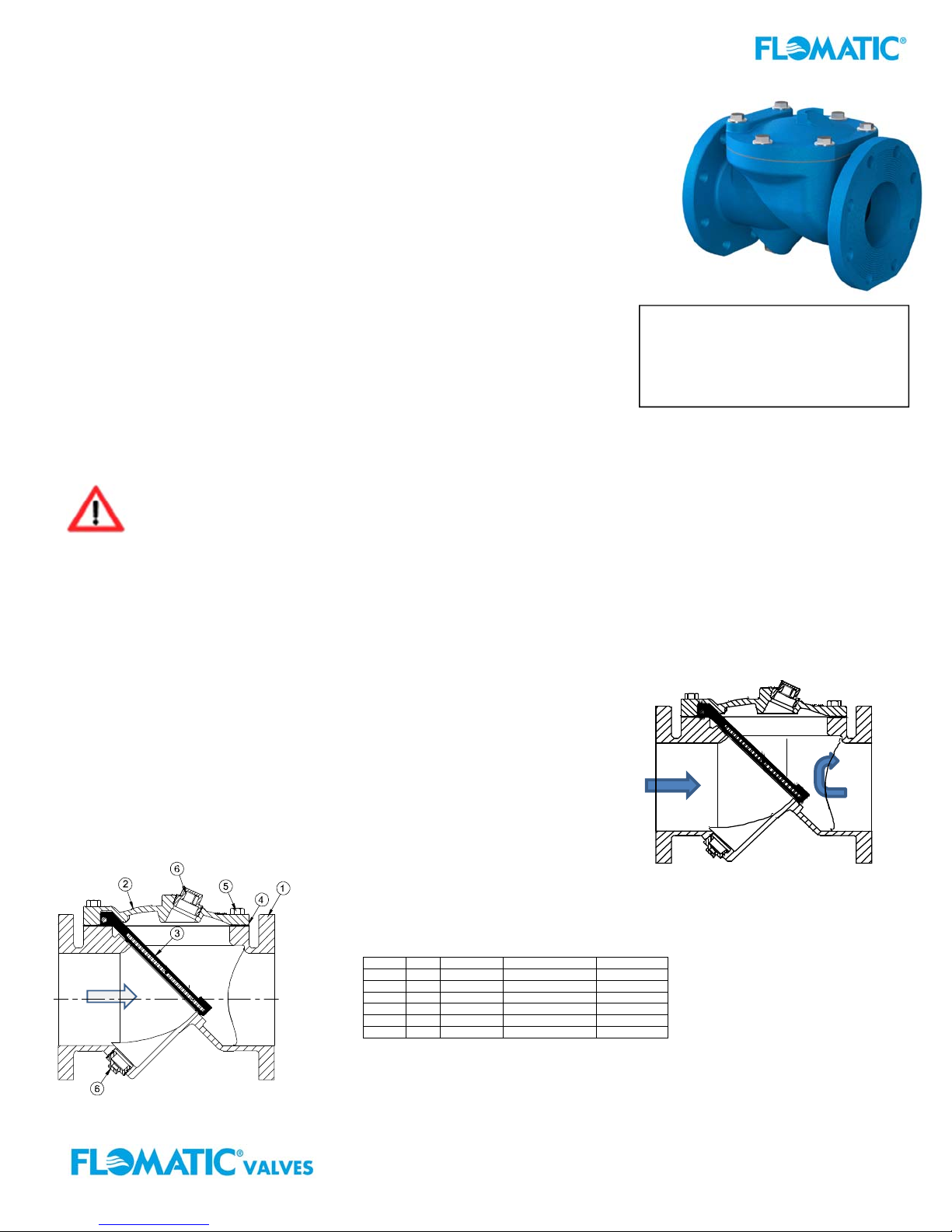
DESCRIPTION OF VALVE OPERATION
The valve is designed to prevent reverse flow automatically. During system flow
conditions, the movement of the fluid forces the disc to the open position allowing
100% flow area through the valve. The valves rubber coated steel disc
automatically returns to the closed position to prevent reverse flow. Several
optional features are a Backflush device, (Model 745 BF), Position Indicator
(Model 745PI), Limit Switch (Model 745LS). These valve product options are
described in more details below.
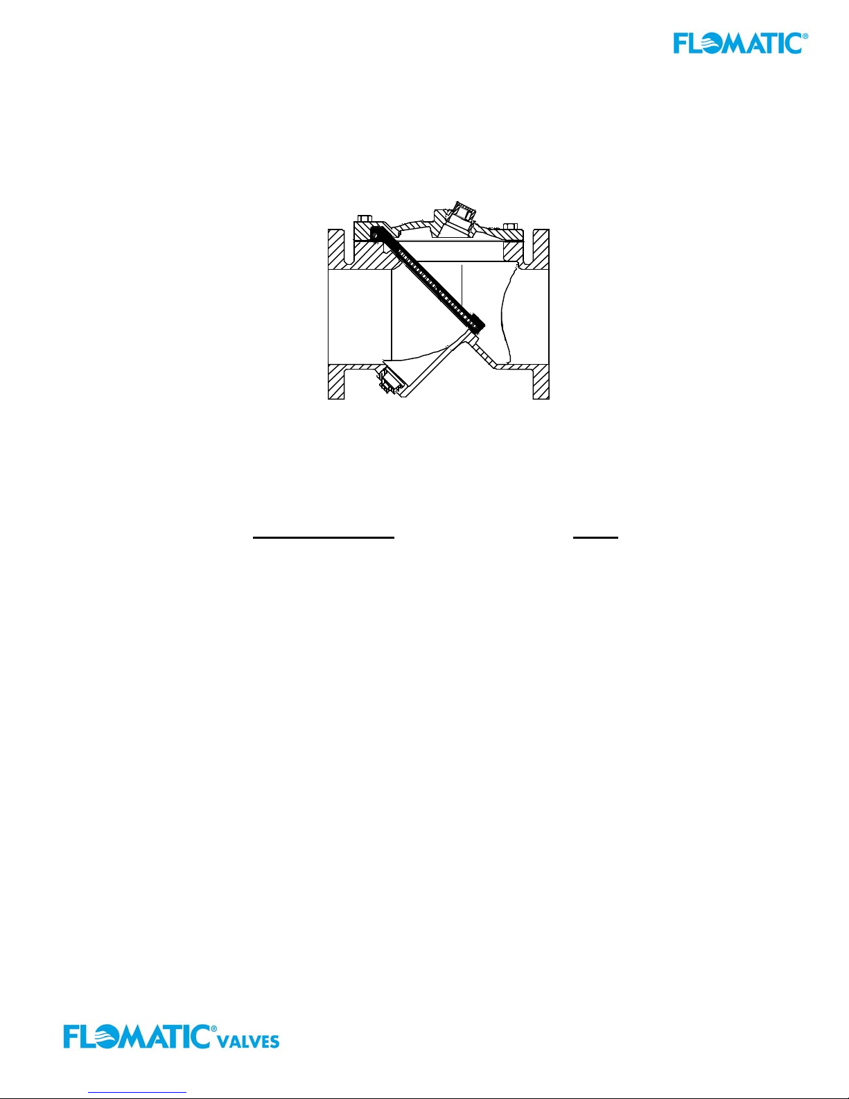
Fig 2. Flo-Flex
Cross Section
®
VALVE CONSTRUCTION
The Flomatic® Flo-Flex
of rugged Ductile Iron with a rubber encapsulated valve disc. The rubber coated valve
disc is the only moving part assuring long life with minimal maintenance. The general
Item # Qty. Description Material ASTM
1 1 Body Ductile Iron A536
is flanged for connection to the
The disc (3) is retained by the cover.
2 1 Cover Ductile Iron A536
3 1 Disc* Buna coated Steel -------4 1 Gasket Buna -------5 A/R Cover Bolt Steel SAE Grade 5
6 1 Plug Malleable Iron --------
*Optional EPRM or Viton Coated Steel
®
Swing Check Valve is constructed
details of construction are
illustrated in Fig. 2. The body (1)
pipeline with an access cover (2).
FIG 1. Flo-Flex®
Swing Check Valve
Flomatic Corp, 15 Pruyn’s Island, Glens Falls, New York 12801
Phone: 518-761-9797 Fax: 518-761-9798 www.flomatic.com
745PI-BF-LS-ASC Rev. B
October 12, 2018
Page 4

INSTALLATION
Correct installation of the Flomatic® Flo-Flex®is important for proper
operation. It may be installed in either horizontal or vertical flow-up
applications. Horizontal installation, with the access port facing up is
recommended for waste water application as it will prevent material
in the fluid to collect on the valve disc. In all installations, the flow
arrow cast in the valve and cover must be pointed in the direction of
flow.
Flanged valves should only be mated with flat-faced pipe flanges
equipped with full-face resilient gaskets. The valve and adjacent
piping must be supported and aligned to prevent cantilevered stress
on the valve. Once the flange bolts or studs are lubricated and
inserted around the flange, tighten them uniformly hand tight. The
tightening of the bolts should then be done in graduated steps using
the crossover tightening method. Recommended lubricated torque
values for use with resilient gaskets (75 durometer) are given in Table 1. If leakage occurs, allow gaskets to absorb fluid
and check torque and leakage after 24 hours. Do not exceed bolt rating or the flange gasket can get damaged and extrude.
Dimensions for 150# Class Valves Max Torque
Valve
Size
(inches) (inches) (inches) (ft.-lbs.) (ft.-lbs.)
2 6 4 5/8” 90 90
2-1/2 7 4 5/8” 90 150
3 7-1/2 4 5/8” 90 150
4 9 8 5/8” 90 150
6 11 8 3/4” 150 150
8 13-1/2 8 3/4” 150 240
10 16 12 7/8” 240 368
12 19 12 7/8” 240 533
14 21 12 1” 368 533
16 23-1/2 16 1” 368 750
18 25 16 1-1/8” 533 750
20 27-1/2 20 1-1/8” 533 750
24 32 20 1-1/4” 750 1200
Table 1 Bolt Torque Chart
Flange
Outside
Diameter
Number
of Bolt
Holes
Bolt
Diameter
150# 300#
TROUBLESHOOTING
Below are some potential problems with solutions to assist you in troubleshooting the valve assembly in a safe manner.
1
2 Leakage at bottom
3
4
Also, visit Flomatic® web page www.flomatic.com for technical product references and parts lists or call customer service 1-800-833-2040.
Problem Solution
Valve disc leaksback when closed
Inspect valve seat area for foreign material. Also, inspect disc for damage and replace. Inspect metal
seating surface and clean if necessary
Remove line pressure and exercise Back-flush device. If leak persists, replace seals in Back-flush
Back-flush device
Leakage at Cover or
Flanges
Valve does not fully
open:
device; see the Back-flush device “Seal Replacement Procedure” on page 4.
Tighten bolts, replace cover seal.
Check for obstruction in valve seat area and/or pipeline; see Disassembly procedure on page 4.
Operating pressure may be less than cracking pressure. If less than 0.5 psig, review application with
factory.
MAINTENANCE
The Flomatic® Flo-Flex®Swing Check Valve requires no scheduled lubrication or maintenance. For service or inspection,
the valves internal parts can be accessed and serviced without removal from the line.
WARNING: The line must be drained and de-pressurized before removing the cover or the bottom plug if
not this may cause bodily harm.
VALVE INSPECTION: DISASSEMBLY & RE-ASSEMBLY
The valves internal parts can be disassembled and serviced without removing it from the pipeline. All service and repair
work performed on the valve shall be performed by a skilled mechanic with proper tools and a power hoist for larger
valves. It is recommended that when disassemble the valve to inspect the rubber valve disc for wear or the valve seat for
deposits.
DISASSEMBLY RE-ASSEMBLY
1. Relieve pressure and drain the pipeline. Refer to
Figure 2 on page 2. Remove the cover bolts (5)
on the top cover.
2. Pry cover (2) loose and lift off valve body. 12” and
larger valves have tapped holes in cover for lifting
eyes.
3. Remove disc (3) and inspect for cracks, tears or
damage in rubber sealing surface.
4.
Clean and inspect parts. Replace worn parts as
necessary and lubricate parts with FDA/NSF
grease such as “Super Lube”.
All parts must be cleaned. Gasket surfaces should be cleaned
with a stiff wire brush in the direction of the serrations or machine
marks. Worn parts, gaskets and seals should be replaced during
reassembly.
1. Lay disc (3) over seat with beaded seating surface
directed down.
2. Lay cover gasket (4) and cover (2) over bolt holes and
disc hinge.
3. Insert lubricated bolts (5) noting that the bolts in the
hinge area are longer than the other cover bolts.
4.
Cover bolts should be tightened to the specifications
shown in Table 2 (next page) during re-assembly.
Flomatic Corp, 15 Pruyn’s Island, Glens Falls, New York 12801
Phone: 518-761-9797 Fax: 518-761-9798 www.flomatic.com
745PI-BF-LS-ASC Rev. B
October 12, 2018
Page 5

Note: The Valve Cover bolts should be tightened to the specifications shown in Table 2
below during re-assembly.
WARNING: Do not use threaded holes in cover for lifting the valve.
Serious injury may result.
BACKFLUSH DEVICE (Model 745 BF)
FIELD INSTALLATION AND MAINTENANCE (OPTIONAL)
BACKFLUSH DEVICE OPERATION:
The optional backflush device assembly (see Fig. 3)
is normally factory installed but is also available for field
installation. The backflush device assembly works like a screw jack but is not designed
to operate during the valve’s Maximum Working Pressure rating. This could damage the
rubber coated valve disc. Therefore, prior to using the backflush device close the
pump isolation valve and bleed off any high line pressure. To operate, turn the
backflush device handle clockwise to move valve disc to and “open” position. This will
allow backflow through the valve. The backflush device handle should turn easily.
When resistance is felt, the disc has reached its “stop” and is in the full “open” valve disc
position. Upon completion of the back flushing operation, turn the handle counterclockwise and the valve disc will automatically return to the “closed” position. It is
important to lock the backflush device handle in the valve disc “closed” position with
the jam nut provided. The system is again ready for normal operation.
FIG. 3
Item # Qty. Description Material
6 1 Bushing Brass
7 1 Shaft Stainless Steel
8 1 Shaft Wiper* Molythane
9 1 O-Ring* Buna
10 1 Handle Stainless Steel
11 1 Jam Nut Brass
12 2 Handle Cap Vinyl
*Recommended Spare Parts
3. Inspect the back-flush device and place in the non-extended position. (The stainless steel shaft should extend a
maximum 1" past the end of the brass bushing.) Apply Teflon thread sealant to brass threads.
4. Insert the threaded end of the assembly into the valve boss. Slowly turn the assembly into the boss taking care not to
cross-thread the bushing. Continue turning the assembly into the valve for a tight fit.
WARNING: If the backflush device stem is not fully turn back to a valve disc
“closed” position the back-flush device shaft/stem could damage the valve disc and
prevent the valve from sealing when put into operation.
BACKFLUSH FIELD INSTALLATION:
When the backflush device is supplied separately and as an optional assembly from
the factory install as follow:
1. Relief the pipe line pressure and drain the pipeline.
2. Carefully, remove the pipe plug (located on the bottom boss of the valve) to insure
that there is no pressure in the line.
Valve Cover Bolt Max Torque
Valve Size Bolt Diameter Torque
(inches) (inches) (ft.-lbs.)
2 ½” 75
2-1/2 ½” 75
3 ½” 75
4 ½” 75
6 ½” 75
8 ½” 75
10 ⅝” 100
12 ⅝” 150
14 ⅝” 150
16 ¾” 250
18 ¾” 250
20 ¾” 250
24 1” 500
Table 2
BACKFLUSH DEVICE (Model 745BF) SEAL REPLACEMENT:
There are two parts (8 & 9) on the backflow actuator that are subject to normal wear. To replace the seals, the
pipeline must first be depressurized and drained. Next, remove the backflow assembly from the valve by turning
the brass bushing (6) counter-clockwise. Disassemble the actuator as follows:
1. Remove one of the vinyl caps (12).
2. Remove the T-Handle (10) and jam nut (11) from the rod (7).
3. Remove the rod (7) from the bushing (6) by screwing in the rod fully clockwise and pull the rod through the
valve end of the bushing (6).
4. Lubricate new seals with FDA approved grease such as “Super Lube” and install in the bushing end grooves.
5. Clean, lubricate, and reinstall rod in bushing.
6. Re-install jam nut (11) and T-Handle (10).
7. Place vinyl cap (12) on handle (10).
8. Apply Teflon thread sealant to bushing and carefully thread into valve taking care not to cross-thread the
bushing
Flomatic Corp, 15 Pruyn’s Island, Glens Falls, New York 12801
Phone: 518-761-9797 Fax: 518-761-9798 www.flomatic.com
745PI-BF-LS-ASC Rev. B
October 12, 2018
Page 6

p
POSITION INDICATOR (Model 745PI)
The optional valve disc Position Indicator (PI) mechanical indicator is factory (see
Fig 4) installed but can also be installed in the field. The Position Indicator visually
indicates to what degree the valve disc is opened or closed. The device is
installed on the access cover and can be installed in the field by going through
the following steps:
1. Remove pipe line pressure and drain the valve.
2. Carefully, remove the top pipe plug (insuring that there is no water pressure in
the line) from the access cover.
3. Apply pipe joint compound to position indicator body (11) threads.
4. Insert the position indicator body (11) and thread in-place.
Item # Qty. Description Material
1 1 Sight Housing Bronze
2 1 Spring Stainless Steel
3 1 Rod Stainless Steel
4 1 Nut Stainless Steel
5 1 Spring Seat Stainless Steel
6 2 O-Rings EPDM
7 1 Sight Base Bronze
8 1 Sight Body Bronze
9 1 Bottom Bushing Acetal
10 1 Rod Wiper Molythane
11 1 Body Bushing Bronze
12 1 Pin Stainless Steel
13 1 Contact Ball Acetal
Fig. 4 Position Indicator
WARNING: Make sure that the position indicator top portion after securely installed pointes in the valves
flow direction. This will ensure proper orientation and function of the position indicator assembly. Damage
to the device and valve disc will accrue if the positi on indi cator is not correctly and exactly aligned with the valv es
flow direction.
Limit Switch (Model 745LS)
The limit switch option (Model 745LS) is factory
installed or field installed (see Fig 5a & 5b) on the
valve access cover and is used in conjunction
with the Position Indicator (PI). A standard limit
switch (Honeywell Model LSH1A or Equal) is
mounted on an epoxy coated steel bracket
Fig. 5a
Side view
Item
Qty. Description Material ASTM
#
1 1 Position Indicator* Various -------2 1 Lever Stainless Steel 301
3 1 Limit Switch** Various -------4 2 SHCS Stainless Steel 18-8
5 4 Lock Washer Stainless Steel 18-8
6 1 Jam Nut Stainless Steel 18-8
7 1 Bracket Hot Rolled Steel A36
8 2 SHCS Stainless Steel 18-8
*For Position Indicator details see Fig.4
**Honeywell Model LSH1A or equal
Electric Switch Replacement Parts: Contact Flomatic
distributor or MICRO SWITCH sales office.
Flomatic Corp, 15 Pruyn’s Island, Glens Falls, New York 12801
Phone: 518-761-9797 Fax: 518-761-9798 www.flomatic.com
for easy wiring, field adjustments and
servicing. The limit switch is SCADA
(Supervisory Control and Data Acquisition)
compatible for applications requiring open/close
indication.
Fig. 5b
To
view
Function: The limit switch when probably adjusted will give an electric
“closed” and/or “open” circuit when valve is open and/or in closed position.
NEMA Ratings: 1, 3, 4, 4X, 6, 6P, 12, 13
UL Ratings: 6 A, 120Vac or 250 Vac, DPST
Installation:
1. First, make sure that the valve is equipped with a Position Indicator (PI).
Attach limit switch bracket (7) with assembly to Position Indicator (PI).
2. Position the assembly so that the switch trips when the valve is closed.
3. Connect wiring to either the normally open or normally closed contact as
shown in the schematic diagram. Follow all local electrical codes.
®
Corporation or contact nearest MICRO SWITCH Authorized
745PI-BF-LS-ASC Rev. B
October 12, 2018
Page 7

PARTS AND SERVICE
Flomatic® Flo-Flex® Model 745 Swing Check Valve parts and service are available from your
local Flomatic
of the valve Model No, Size, Type and Working Pressure located on the valve. Also the
installation date and contact:
A Flomatic sales representative will quote prices for parts or arrange for service as needed.
®
representative or the factory. Please, make note on the front page of this O&M
Flomatic Corporation
15 Pruyn’s Island Drive
Glens Falls, NY 12801
Phone: (518) 761-9797 or 1-800-833-2040
Fax: (518) 761-9798
www.flomatic.com
FLOMATIC
LIMITED ONE-YEAR WARRANTY (Flo-Flex
that its products are free from defects in materials and workmanship. Flomatic
valve covered by this warranty that is found to be defective within one year, unless otherwise stated below, from
the time of sale. This warranty will be void if the product has been modified in any way by the purchaser, or is
subjected to unreasonable use.
EXCLUSION OF WARRANTIES
®
Flomatic
expressed limited warranties described herein. The implied warranties of merchantability and fitness for a
particular purpose are hereby disclaimed by Flomatic
the description on the face hereof.
WARNING-NOT DESIGNED, INTENDED OR PERMITTED IN NUCLEAR FACILITY APPLICATIONS.
FLOMATIC VALVES ARE NOT DESIGNED OR ENGINEERED FOR USE IN ANY NUCLEAR FACILITY OR IN
CONJUNCTION WITH ANY NUCLEAR FACILITY OR SUPPORT FACILITY. USE OF ANY OF FLOMATIC’S
PRODUCTS IN ANY SUCH APPLICATION IS MISUSE OF THESE PRODUCTS AND VOIDS ALL
WARRANTIES CONTAINED HEREIN, EXPRESSED AND IMPLIED, OF MERCHANTABILITY AND FITNESS
FOR PARTICULAR PURPOSE.
Corporation makes no warranties, expressed or implied, with respect to its valves, other than the
®
LIMITED WARRANTY
®
Model 745 Swing Check Valves) Flomatic® Corporation warrants
®
Corporation. There are no warranties that extend beyond
®
Corporation will replace any
Flomatic Corp, 15 Pruyn’s Island, Glens Falls, New York 12801
Phone: 518-761-9797 Fax: 518-761-9798 www.flomatic.com
www.flomatic.com
1-800-833-2040
745PI-BF-LS-ASC Rev. B
October 12, 2018
 Loading...