

Page 1

Cycle Gard® Model CNA
NEW
Flomatic Corporation
Constant Pressure Pump Control
Model CNA
Sizes: 1 1/4”- 2” NPT
1 1/2”-12” - 150# Flange
Applications
¾ Irrigation and Sprinkler Systems
¾ Booster Pump Systems
¾ Domestic Well Water Systems
¾ Municipal/Public Water Systems
Product Specification
• Connection: Female NPT or 150# Flanged
• Max pressure: 300 PSI (20 bar)
• Max temperature: 180°F (80°C)
• NSF Approved Epoxy Powder
• Replaceable Seal
• Field Adjustable
• Cover Chamber air bleed
• Pilot Control Isolation Valves
• Flow Control Valve
Materials
Valve Body: Ductile Iron A536
Elastomers: Reinforced Buna-N
Internals: Un-Leaded Bronze
Spring: Stainless steel
Fasteners: Stainless steel
Coating: NSF approved epoxy powder
Pilot: Un-Leaded Bronze 61<5 Prop 65
Features
• Maintains a constant downstream (outlet) pressure
• Adjustable by-pass (shorten pump shut down time)
• Strong Ductile Iron Valve Body construction
• Unleaded pilot control - California Prop 65 compliant (61< 5 marking)
• Double Guided Diaphragm Assembly
• Field Adjustable Pressure control
• Vertical or Horizontal installation
• Lower friction losses
•
Product Warranty: Flomatic three year control valve product warranty applies.
15 Pruyn’s Island Drive, Glens Falls, New York 12801
Phone: 518-761-9797 Fax: 518-791-9798
High Quality Valves Built to Last . . .
Flomatic Corporation
www.flomatic.com
Page 2
p
Cycle Gard® Model CNA
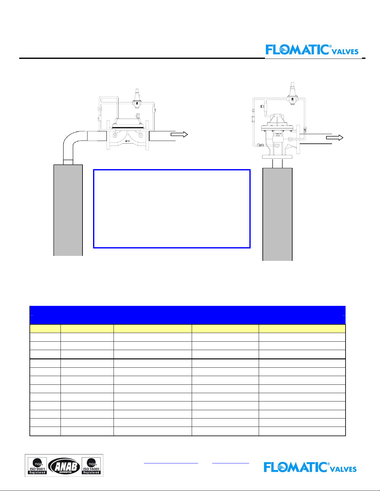
Typical Well Head
Installation using Model CI
Installation using the
Cycle Gard
WATER
WELL
; Reduces Installation time
; Lower Friction Loss
; 90° Valve Eliminates Elbow
; Eliminates Spool Pieces
; Field Adjustable
; Eliminates Additional Hardware
; Can be installed horizontally
; Fusion Epoxy Coated
WATER
WELL
Flomatic CYCLE GARD® CNA is a pilot operated pump pressure regulating control valve incorporating
an adjustable unleaded pressure reducing pilot and an external adjustable by-pass. The unit is designed to
give constant pressure and prevent pump cycling during normal operation. Isolation valves are provided for
manual o
Size Part Number Connection Pressure Range Pumping Rate
1 1/4" CNA1010B NPT Female Threaded 25-175 p.s.i. 15 to 30 gpm
1 1/2" CNA1010C NPT Female Threaded 25-175 p.s.i. 15 to 75 gpm
2" CNA1010D NPT Female Threaded 25-175 p.s.i. 25 to 125 gpm
1 1/2" CNA1011C 150# Flange 25-175 p.s.i. 15 to 75 gpm
2" CNA1011D 150# Flange 25-175 p.s.i. 25 to 125 gpm
2 1/2" CNA1011E 150# Flange 25-175 p.s.i. 50 to 200 gpm
3" CNA1011F 150# Flange 25-175 p.s.i. 75 to 300 gpm
4" CNA1011G 150# Flange 25-175 p.s.i. 100 to 600 gpm
6" CNA1011J 150# Flange 25-175 p.s.i. 200 to 1300 gpm
8" CNA1011K 150# Flange 25-175 p.s.i. 400 to 2400 gpm
10" CNA1011L 150# Flange 25-175 p.s.i. 600 to 3700 gpm
12" CNA1011M 150# Flange 25-175 p.s.i. 800 to 7200 gpm
eration and for inline servicing of the external Y-strainer and pilot controls.
Cyclegard CNA
Model CNA101 Constant Pressure Angled Body Pump Control Valve
®
CNA
15 Pruyn’s Island Drive, Glens Falls, New York 12801-4424
Phone: 1-800-833-2040 Fax: 518-791-9798
www.us.water.danfoss.com www.flomatic.com
Model CAN Rev: 030510
 Loading...