

Flomatic 8080 Installation Manual
g
Backflow Preventer Installation Instructions
Model 8080 – ASSE 1024
FAILURE TO FOLLOW THESE INSTRUCTION WILL VOID ANY WARRANTY
The Danfoss Flomatic Model 8080 is designed to be installed down stream from the house wa ter meter where a
cross connection could result in pollution of potable water. This product is intended for use with copper or plastic
pipe only (do not use on steel pipe which is rated at a higher pressure rating). If a health hazard could result from a
cross connection, use a Flomatic RPZE Reduced Pressure Principle Backflow Preventer.
Installation Instructions:
1. Before installing the Model 8080, flush lines to
remove all sediment and foreign matter from the
line.
2. Plastic union nuts shall be hand tightened only.
Insure that “O”-rings (see #4 in figure) are properly
positioned before tightening union nuts.
DO NOT use tools as it will damage union nut.
3. Use only Teflon tape for sealing pipe threads.
DO NOT use Teflon tape or pipe sealant on union
nut threads.
4. DO NOT install in areas subject to freezing. Valve
will burst and cause severe damage to property
due to flooding.
5. A suitable strainer should be installed upstream of
the device when possible.
6. Caution:
As in any piping system, provisions
should be made to eliminate any water hammer
and thermal expansion as these conditions will
create damaging and dangerous high internal
pressures.
Maintenance:
Servicing the Model 8080 involves replacing the check
valve assemblies.
1) Turn off water supply and releif pressure in
system.
2) Open downstream fixture to relieve pressure to
valve.
3) After isolating backflow preventer, remove it
from line by loosening union nuts.
4) Remove check assemblies.
5) Clean inside of the valve body and replace
check assemblies in correct direction of fl ow.
Re-install the valve, hand tightening
union nuts.
Caution:
DO NOT USE TOOLS FOR
TIGHTENING UNION NUT. HAND
TIGTENING IS SUFFICIENT FOR SEAL.
1 Year Limited Warranty: Danfoss Flomatic valves are guaranteed against defects of materials or workmanship when
used for the services recommended. If in any recommended service, a defect develops due to material or workmanship,
and the device is returned, freight prepaid, to Danfoss Flomatic within 12 months from the date of purchase, it will be
repaired or replaced free of charge. Danfoss Flomatics’ liability shall be limited to our agreement to repair or replace the
valve only.
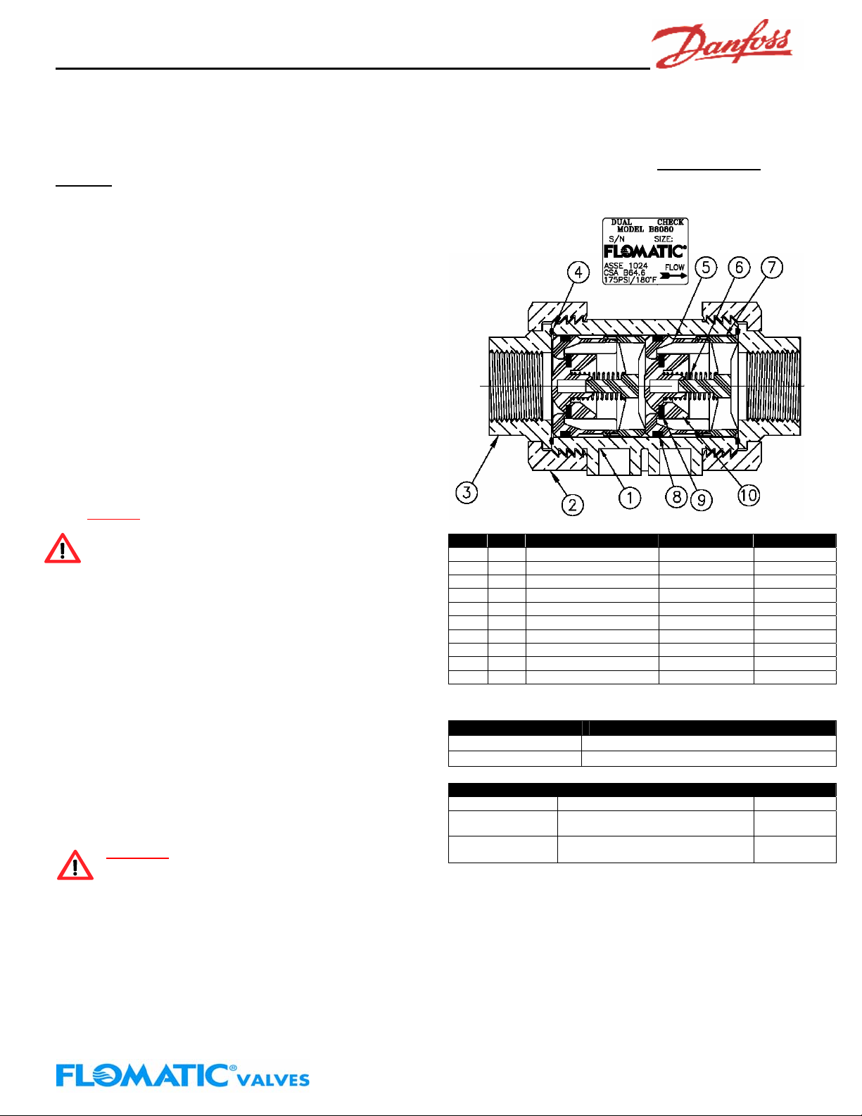
Item Qty Description Material ASTM
1 1 Valve Body NORYL® GFN2-780S
2 2 Tailpiece Union Nut Brass B16
3 2 Tailpiece Brass B16
4 2 Tailpiece O-Ring BUNA-N 5 2 Check Housing DELRIN® 6 2 Check Spring Stainless Steel 302
7 2 Check Spring Retainer DELRIN® 8 2 Check O-Ring BUNA-N 9 2 Check Disc SILICONE Grade 60
10 2 Check Poppet NORYL® GFN2-780S
NORYL® is a GE registered trademark & DELRN® is a DuPont registred
trademark.
Valve Size Part Number
¾” B8080
1” B8081
Repair Kit Description Part Nimber
Rubber Repair Kit 2 Valve seat discs-2 Union O-rings-
Major Repair Kit 2 Check Seats-2 Valve seat discs-
Repair Parts Kits
2 Seat O-rin
2Body O-Rings-2 Seat O-Rings
Danfoss Flomatic
B80RK00
s
89600PO
Danfoss Flomatic Corp, 15 Pruyn’s Island, Glens Falls, New York 12801
Phone: 518-761-9797 Fax: 518-761-9798 www.flomatic.com
April 21,2004 Rev. F (7/08)
8080
 Loading...