

Page 1
Backflow Preventer Specification Submittal Sheet
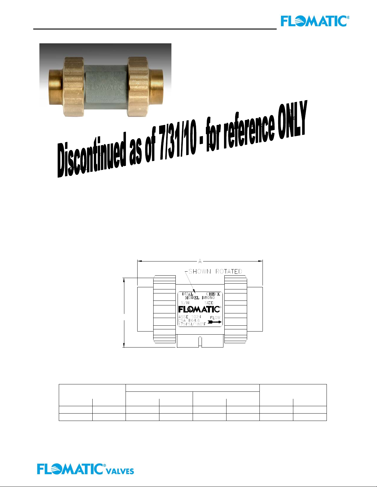
Models 8080
APPLICATION:
Designed for installation on potable water lines to
protect against both backsiphonage and backpressure
of polluted water into the potable water supply.
Assembly shall provide protection where a potential
health hazard does not exist. For use in indoor and
outdoor meter box as primary domestic water
protection. Lead free body and checks ensure safe
FEATURES:
Sizes: □¾” □1”
Max working pressure: 175psi
Max temperature: 180ºF
Connection: Threaded ANSI B 1.20.1
OPTIONS:
□ – Female NPT connection (standard)
□ FC – Female Copper Sweat
B
SIZE DIMENSIONS WEIGHT
A B
inch mm inch mm inch mm lbs kg
¾ 20 4-3/8 111 2-7/16 62 1 .5
1 25 4-3/8 111 2-7/16 62 1 .5
drinking water while providing maximum corrosion
resistance.
STANDARDS COMPLIANCE:
● ASSE
● CSA
MATERIALS:
Main valve body:
Elastomers:
Polymers: Delrin®, NSF Listed
Springs: Stainless Steel, 300 Series
Union End Nuts: Bass
®
Listed 1024
®
Listed B64.6
Flomatic Corporation
Noryl
Buna Nitrile (FDA approved)
Flomatic Corporation, 15 Pruyn’s Island, Glens Falls, New York 12801
Phone: 518-761-9797 Fax: 518-761-9798 www.flomatic.com
Novermber 29, 2004 Rev: 5 (6/11)
Specification Sheet 8080
Page 2
Backflow Preventer Specification Submittal Sheet
Models 8080E
i
a
s
P
p
k
10
69
S
S
O
L
E
R
U
S
S
E
R
P
41 6
855
428
214
5
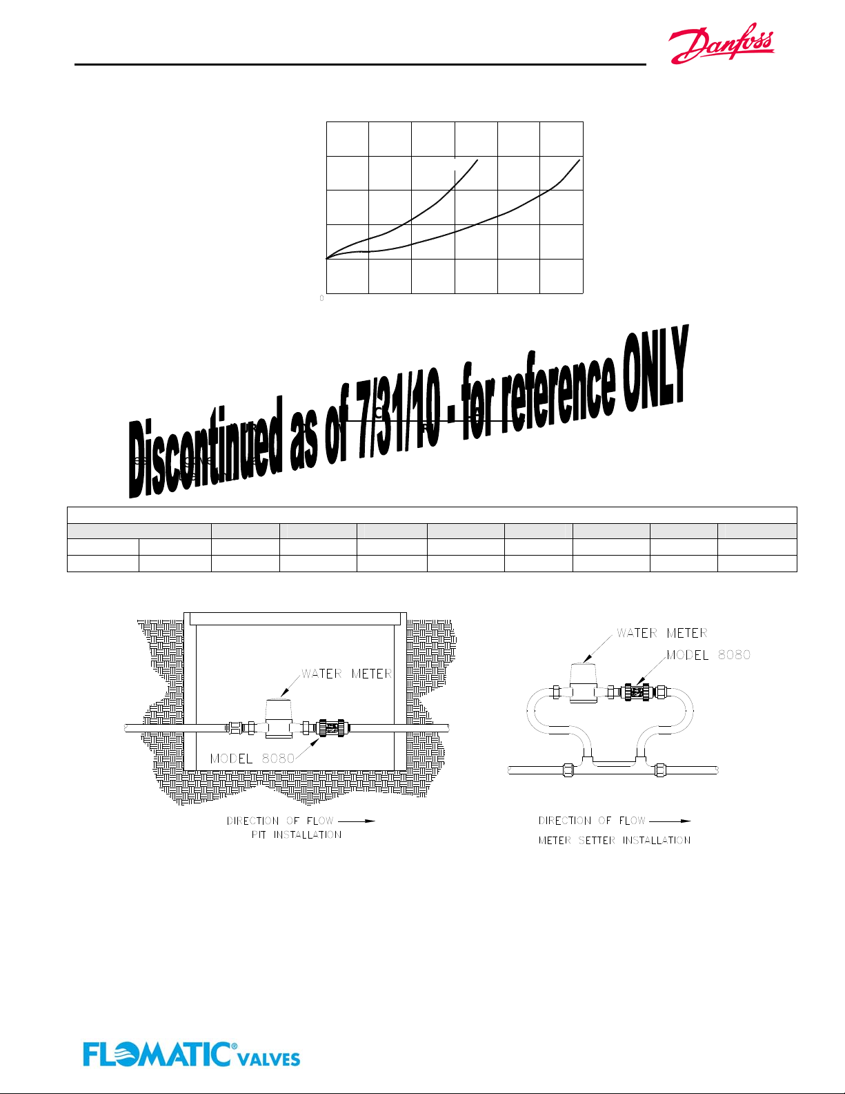
3/4" (20 mm)
1" (25 mm)
10 30 gpm20
.63 1.26 1.89 lps
15 25
.95
FLOW RATE
1.58.32
(Established by Approval Agencies)
▲ RATED FLOW
TYPICAL INSTALLATION:
FAILURE TO FOLLOW THESE INSTRUCTION WILL VOID ANY WARRANTY
Local codes shall govern installation requirements. Unless otherwise specified, the installation shall be in
accordance with the manufacturer’s instructions and the latest edition of the Uniform Plumbing Code. The
installation shall be made so that no part of the unit can be submerged.
Danfoss Flomatic
Capacity in GPM & liters per second (Schedule 40 Pipe)
Pipe Size
5 ft/sec
¾” 20 mm
1” 25 mm
8
13
1.5 M/sec
30
49
7.5 ft/sec
12
20
2.3 M/sec
45
75
10 ft/sec
17
27
3 M/sec
64
102
15 ft/sec
25
40
4.5 M/sec
94
151
SPECIFICATIONS:
The Dual Check Valve shall be ASSE® Listed 1024. The main body shall be Noryl, the check assemblies shall be
DELRIN®. The seal ring and o-rings shall be Buna Nitrile. The Dual Check Valve shall be a Flomatic Model 8080.
WARRANTY: Flomatic valves are guaranteed against defects of materials or workmanship when used for the services
recommended. If in any recommended service, a defect develops due to material or workmanship, and the device is returned,
freight prepaid, to Flomatic corporation within 12 months from the date of purchase, it will be repaired or replaced free of charge.
Flomatic Corporations’ liability shall be limited to our agreement to repair or replace the valve only.
Flomatic Corporation, 15 Pruyn’s Island, Glens Falls, New York 12801
Phone: 518-761-9797 Fax: 518-761-9798 www.flomatic.com
Novermber 29, 2004 Rev: 5 (6/11)
Specification Sheet 8080
 Loading...