

Page 1
Swing Check Valves Installation Instructions
Models 745 with Backflush
FAILURE TO FOLLOW THESE INSTRUCTION WILL VOID ANY WARRANTY
CAUTION: Installation of model 745 must be performed by qualified, licensed personnel. Faulty installation could result
in an improperly functioning device.
Backflush field installation: The backflush is supplied as an optional assembly from the factory.
WARNING: Removal of the pipe plug or backflush while under pressure may cause bodily harm.
1. Remove line pressure and drain valve.
2. Remove pipe plug from bottom boss of the valve.
3. Inspect the backflush rod and place in the non-extended position. (The rod should extend about 1” past the
end of the brass bushing.) Apply Teflon thread sealant to brass threads.
4. Insert the threaded end of the assembly into the valve boss. Slowly turn the assembly into the boss taking
care not to cross-thread the bushing. Continue turning the assembly into the valve for a tight fit.
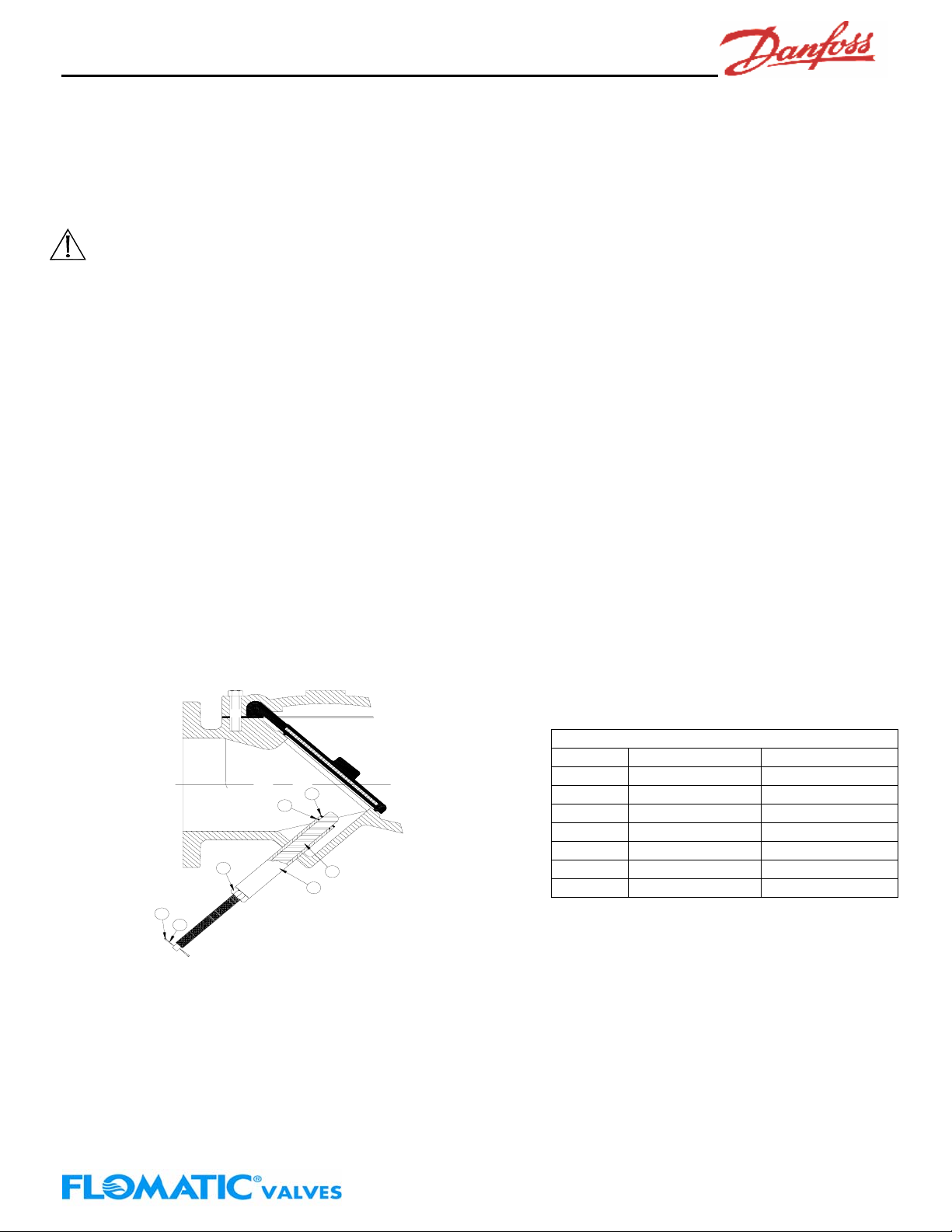
Backflush seal replacement: There are two parts (8&9) on the backflush that are subject to wear. To replace the
seals, the pipeline must first be depressurized and drained. Next, remove the backflush assembly from the valve by
turning the brass bushing (6) counterclockwise. Disassemble the actuato r as follows:
1. Remove on the retainer rings (12) with a sharp-blade screwdriver.
2. Remove the T-Handle (10) and jam nut (11) from the rod (7).
3. Remove the rod (7) from the bushing (6) by screwing in the rod fully clockwise and pull the rod thru the
valve end of the bushing (6).
4. Lubricate new seal with FDA approved grease such as Lubriko #CW-606 and install in the bushing end
grooves.
5. Clean, lubricate and reinstall rod in bushing.
6. Re-install jam nut (11) and T-Handle (10).
7. Snap retaining ring (12) on handle (10).
8. Apply Teflon thread sealant to bushing and carefully thread into valve taking care not to cross-thread
the bushing.
8
9
12
11
10
7
6
Item Description Material
6 Bushing Brass
7 Rod Stainless Steel
8 Rod Wiper Molythane
9 O’Ring Buna-n
10 Handle Carbon Steel
11 Jam Nut Brass
12 Retaining Ring Steel
1 Year Limited Warranty: Danfoss Flomatic valves are guaranteed against defects of materials or workmanship when used for the
services recommended. If in any recommended service, a defect develops due to material or workmanship, and the device is
returned, freight prepaid, to Danfoss Flomatic within 12 months from the date of purchase, it will be repaired or replaced free of
charge. Danfoss Flomatics’ liability shall be limited to our agreement to repair or replace the valve only.
Indicator Rod Part List
Danfoss Flomatic
Danfoss Flomatic Corp, 15 Pruyn’s Island, Glens Falls, New York 12801
Phone: 518-761-9797 Fax: 518-761-9798 www.flomatic.com
May 26,2004 Rev. A
745_backflow
 Loading...