

Page 1
FLOMAG s.r.o.
V Aleji 180/20a
CZ-620 00 Brno
Czech Republic
tel: +420 541212539
fax: +420 549240356
e-mail: info@flomag.com
www.flomag.com
Magnetic Flowmeter
FLOMAG
®
3000
Installation and Operation
Page 2

FLOMAG 3000 -
Installation and Operation Manual
2
Page 3
FLOMAG 3000 -
Installation and Operation Manual
3
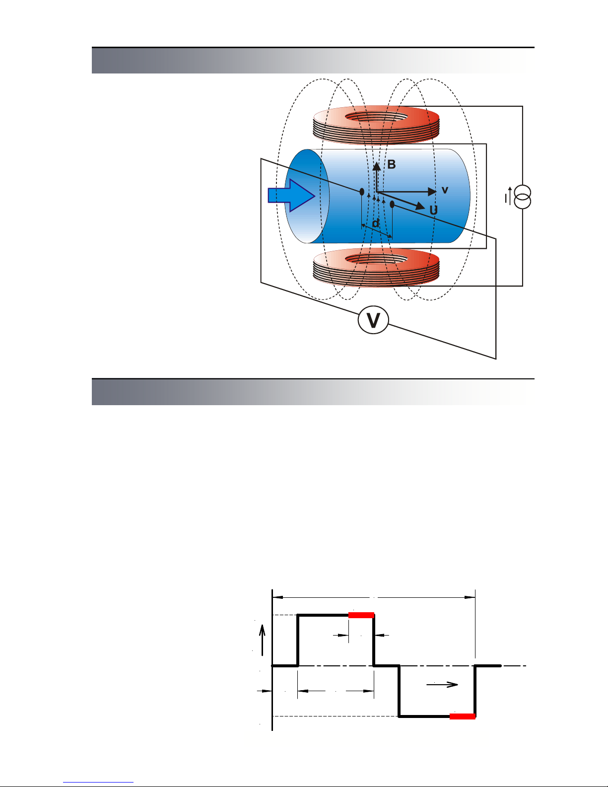
An magnetic flowmeter is used
for volume flow measurement of
electrically conductive liquids.
Measurement principle is based
on Faraday law on electromagnetic induction. A sensor consists of a non-magnetic tube
with non-conductive lining,
measuring electrodes and two
coils generating electromagnetic field. Flowing liquid forms
a conductor. Magnetic field induces voltage U in this conductor that is proportional to magnetic induction B, distance between electrodes d and flow
velocity v.
U = B x d x v
As magnetic induction and distance between electrodes are
constant, induced voltage is
proportional to velocity of liquid
flow in the tube. Volume flow
rate is product of flow velocity
and tube cross section.
Q = v x S
Fig.1 - Principle of measurement
Principle of measurement
Technical solution
The magnetic flowmeter itself
consists of two basic parts – a
flow sensor and a converter.
The converter can be either an
integral part of the sensor
(compact version) or separated,
connected with the sensor using a cable (remote version).
The sensor consists of a nonmagnetic tube with nonconductive lining, measuring
electrodes, excitation coils and
cables. There are various sensor versions available enabling
connection to adjacent tubes
with flanges (type P) and fittings
(gas fitting type G or food industry fitting type V) or wafer which
are installed between flanges
using clamps (type B). Nonconductive lining can be made
of technical rubber (types TG,
MG or NG) or Teflon (type T).
The converter is used for generating excitation current in coils,
processing of signal from measuring electrodes, displaying of
measured data and generating
output signals. Current in excitation coils has constant value
250 mA or 125 mA and is pulse
generated with alternating polarity to avoid permanent magnetization of the sensor. Excitation pulse frequency can be
chosen from six values – 25 Hz,
12,5 Hz, 8,33 Hz, 6,25 Hz,
3,125 Hz and 1,56 Hz. Excitation current of 250 mA with excitation frequency 3,125 Hz is
suitable for all standard applications. Other settings can be
used for specific applications.
Excitation current and frequency are factory set before
sensor calibration and their later
modifications are not allowed.
Voltage induced in measuring
electrodes is measured always
on the end of excitation pulse
when magnetic field is steady.
Each excitation pulse is followed by refreshing period. Signal processing and parameter
setting are performed digitally
and the converter contains no
setting controls or other moving
parts what ensures its high reliability and long-term stability.
T
t
I
+I
-I
m
m
1/8T 3/8T
1/8T
0
Fig. 2 - Excitation pulse form
Page 4
FLOMAG 3000 -
Installation and Operation Manual
4
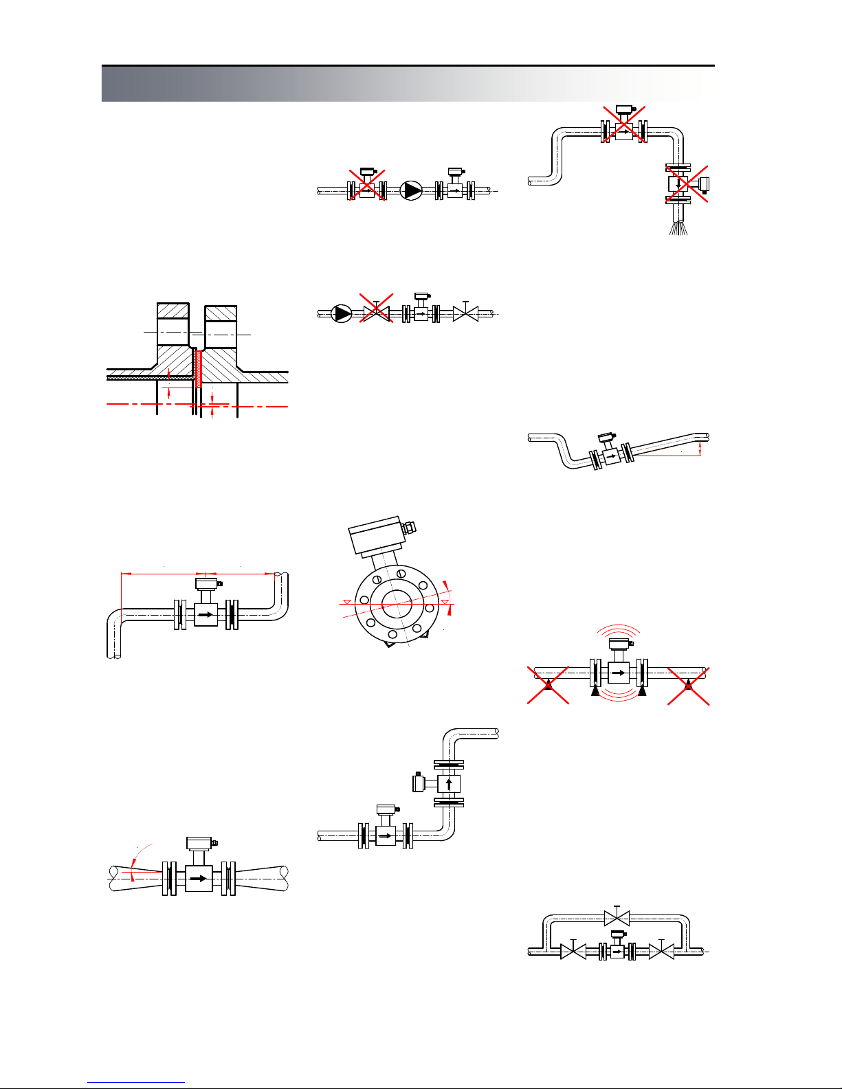
min 5 x DN min 3 x DN
The flowmeter will give the best
results when flow of liquid is
steady. Therefore a few basic
recommendations should be
observed for its locating in a
pipeline. There should be no
transitions between the sensor
and the adjacent pipeline that
could be a source of turbulence.
Correct axial alignment should
be observed during installation.
A gasket should not exceed
internal edges of tubes.
If more interfering elements are
present near the sensor (e.g.
bends, fittings), required steady
length should be multiplied by
number of these interfering elements.
Reductions with slopes up to 8°
can be included in steady
lengths.
x
x
Minimum straight steady
lengths of pipeline are required
on both sides of the flow sensor. Their lengths have to be
proportional to pipeline internal
diameter.
Fig. 3 - Overlaps
Fig.4 - Steady lengths
8
°
m
a
x
m
a
x
4
5
°
min 2 x DN
Fig.5 - Reduction
If water in the pipeline is
pumped by a water pump, the
sensor should be always located behind the pump to avoid
low pressure that can damage
the sensor. Steady length of at
least 25DN is required between
the pump and the sensor.
Fig. 6 - A water pump
For the same reason, never
locate stop valves behind the
sensor.
Fig. 7 - Stop valves
The sensor can work both in
horizontal and vertical positions;
only axis of measuring electrodes inside the sensor must
always remain in horizontal position and tapping of the sensor
should be directed upwards at
horizontal installations.
Fig. 8 - Electrode axis
For vertical installations, liquid
should flow upwards.
Fig. 9 - Vertical installation
To ensure correct measurement
and to avoid air lock, whole
sensor cross section should be
flooded. Therefore never locate
the sensor in upper parts of the
pipeline or in vertical positions
with liquid flowing downwards.
Fig.10 - Danger of air lock
If permanent flooding of whole
pipeline cross section cannot be
ensured, it is possible to locate
the sensor in a low water trap
so that it can be always completely flooded. Free water discharge should be located 2DN
higher than the sensor.
Fig.11 - Permanent flooding
To avoid vibrations that could
damage the sensor, ensure that
the adjacent pipeline is always
supported as near to the sensor
as possible.
Fig.12 - Danger of vibrations
Where continuous flow of fluid
is required and removal of the
sensor is impossible, a bypass
should be installed. The same
applies for locations where sensor removal would require
draining of too long part of the
pipeline.
Fig. 13 - A bypass
Installation instructions
Page 5
FLOMAG 3000 -
Installation and Operation Manual
5
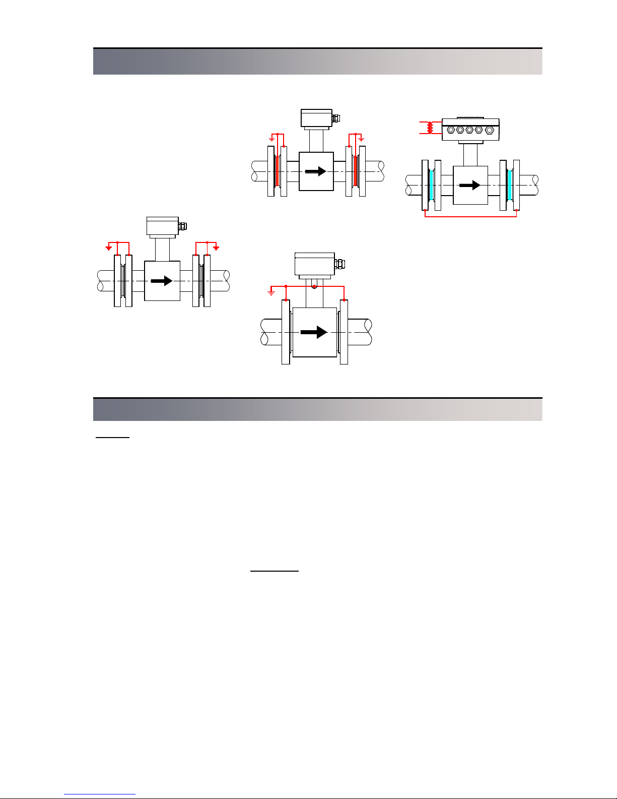
Correct function of the magnetic
flowmeter requires perfect electrical connection between the
sensor and the adjacent pipeline, grounding potential and the
power supply protective wire.
For the flanged sensor with the
adjacent conducting pipeline,
flanges should be electrically
connected and the pipeline
grounded.
If the adjacent pipeline is
non-conductive, grounding rings
should be inserted in it or
equivalent method should be
Fig.16: Grounding rings
Fig.17. The wafer sensor
Fig.18: Cathodic protection
Fig.15: Grounding of flanges
connection of sensor clamping
flanges with grounding point of
the sensor.
If electric current flows through
the pipeline, e.g. for pipeline
cathodic protection against corrosion, the sensor should be
electrically isolated from the
adjacent pipeline. The sensor
should be bridged over using a
wire and galvanic isolation of
the flowmeter power supply
should be provided so that the
flowmeter can be isolated from
all other devices.
Sensor grounding
Selection of suitable sensor lining and electrode material
Linings
Sensors have a non-conductive
lining from various materials.
Choice of material depends on
measured fluid characteristics.
· Technical rubber
Technical rubber is suitable for
low aggressive fluids with operational temperatures from 0.1
°C to 70 °C. It fits for most water management and sewage
treatment applications. It is
manufactured in two variants
“TG” – with hard structure and
“MG” – with soft structure. Soft
structure is used for fluids with
higher content of abrasive particles (e.g. sand). It is not suitable for drinking water.
· Resistant rubber
Type “NG” is suitable for medium aggressive fluids with operational temperatures from 0.1
°C to 90 °C. It can be used for
measurement of hot service
water, condensate etc., as well
as for drinking water. If tem-
perature 100 °C can be exceeded, Teflon (PTFE) lining is
recommended.
· Teflone or Hallar
Type “T” is the most universal
lining for aggressive fluids with
operational temperatures from 20 °C to 150 °C. It is suitable for
chemical and food industry applications.
Electrodes
Choice of material of measuring
electrodes also depends on
measured fluid characteristics.
· Stainless steel – “Ss”
Standard electrodes are made
of stainless steel AISI 316Ti.
They are suitable for all usual
water based fluids and for lower
concentrations of acids and
caustics.
· Hastelloy C-22 – “Ha”
For some special applications,
material of higher quality should
be used. Hastelloy C-276 elec-
trodes are characterized by increased resistance against acids and caustics and usually are
suitable for most of industrial
applications.
· Titanium - „Ti“
Suitable for some acids,
lyes, chlorine, urea and sewage.
· Platinum – “Pt”
For particularly aggressive fluids like concentrated acids and
caustics, chemically extremely
resistant material should be
chosen – platinum. However,
high cost of this material is its
essential drawback.
* Note – We can recommend
suitable lining and electrode
materials for your particular application.
used to connect measured fluid
electrical potential with ground.
For the wafer sensor, grounding
can be provided by electrical
Page 6
FLOMAG 3000 -
Installation and Operation Manual
6
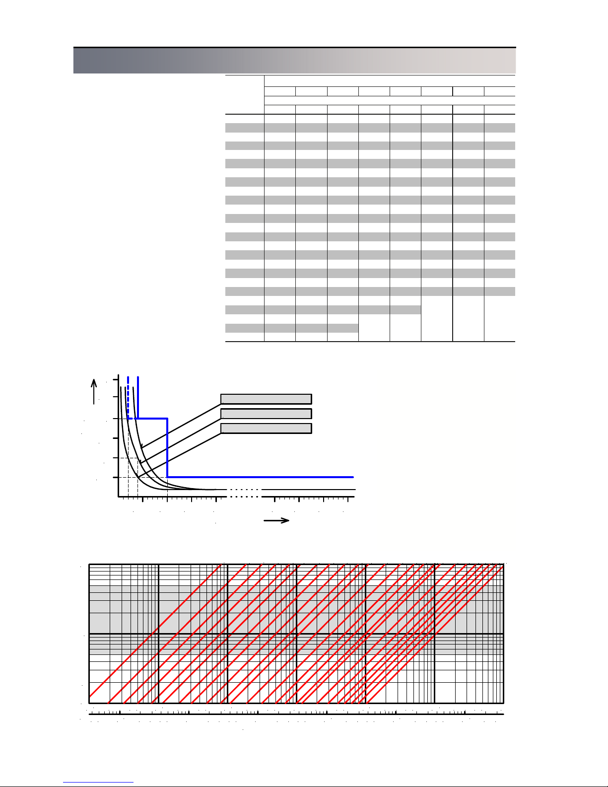
Converter is capable to detect
flow rates as low as 0.1 m/s.
Upper limit is determined by
capability of liquid to maintain
continuous flow at higher velocities. This is usually true for flow
rates up to 12 m/s.
Measurement error rapidly
increases for too low flow rates,
as can be seen in the diagram.
It shows limits of maximum relative measurement error as function of liquid flow rate.
On the other side, too high
flow rate causes discontinuity of
flow and results in chaotic turbulence and vacuum traps. This
results in instable measurement
and too high drift of flow rate
values.
Ideal operational range of the
sensor is in range from 0.5 to 5
m/s. This range is highlighted in
the diagram for correct size selection.
Flow rate ranges for individual
sizes are chosen to meet EN
14154 standard and they are
shown in table. Preferred
ranges are highlighted in bold.
For non-specified working meters, other range can be also
specified on request.
If range is not specified in a
purchase order, the sensor will
be calibrated in preferred range
in accordance with the table
above.
Correct sensor size selection
10
1
0.1
Flow velocity [ m/s ]
Volume flow rate
10 2 3 4 5 10 2 3 4 5 10 2 3 4 5 10 2 3 4 5 10 2 3 4 5 10
-2
-1
0
2
3
DN 10
D
N 20
DN 25
D
N 32DN
4
0
D
N 50DN 65DN 80
D
N
100
DN 125
D
N
1
50
D
N 15
D
N
20
0
D
N
25
0
DN 300
D
N 350DN
400
DN 500
D
N
600
D
N
700
D
N 800DN
900
D
N 1000
DN 1200
2 3 4 5 10
10 2 3 4 5 10 2 3 4 5 10 2 3 4 5 10 2 3 4 5 10 2 3 4 5 10
-1
3
4
2 34 5
3
2
Tab. Sensor ranges in m3/h according to their sizes
Fig. Limit of maximum relative error of measurement
Diagram for correct sensor size selection.
DN
S10 A25 B25 C25 C50 D25 D50 D100
Range Q3/Q1
R10 R25 R25 R25 R50 R25 R50 R100
10
1 0.63
1
1.6 1.6 2.5 2.5 2.5
15
2.5 1.6
2.5
4 4 6.3 6.3 6.3
20
4 2.5
4
6.3 6.3 10 10 10
25
6.3 4
6.3
10 10 16 16 16
32
10 6.3
10
16 16 25 25 25
40
16 10
16
25 25 40 40 40
50
25 16
25
40 40 63 63 63
65
40 25
40
63 63 100 100 100
80
63 40
63
100 100 160 160 160
100
100 63
100
160 160 250 250 250
125
160 100
160
250 250 400 400 400
150
250 160
250
400 400 630 630 630
200
400 250
400
630 630 1000 1000 1000
250
630 400
630
1000 1000 1600 1600 1600
300
1000 630
1000
1600 1600 2500 2500 2500
350
1000 630
1000
1600 1600 2500 2500 2500
400
1600 1000
1600
2500 2500 4000 4000 4000
450
1600 1000
1600
2500 2500 4000 4000 4000
500
2500 1600
2500
4000 4000 6300 6300 6300
600
2500
4000
6300 6300 10000 10000 10000
700
2500
4000
6300 6300 10000 10000 10000
800
4000
6300
10000 10000
900
4000
6300
10000 10000
1000 6300
10000
1200 6300
10000
Range marking
0.25 0.5
0.5
1
1.5
2
2.5
3
0.75 1
±F
10 11 12
[ % ]
v [ m/s ]
9
DN400..1200
DN10..25, 250..350
DN32..200
Page 7
FLOMAG 3000 -
Installation and Operation Manual
7
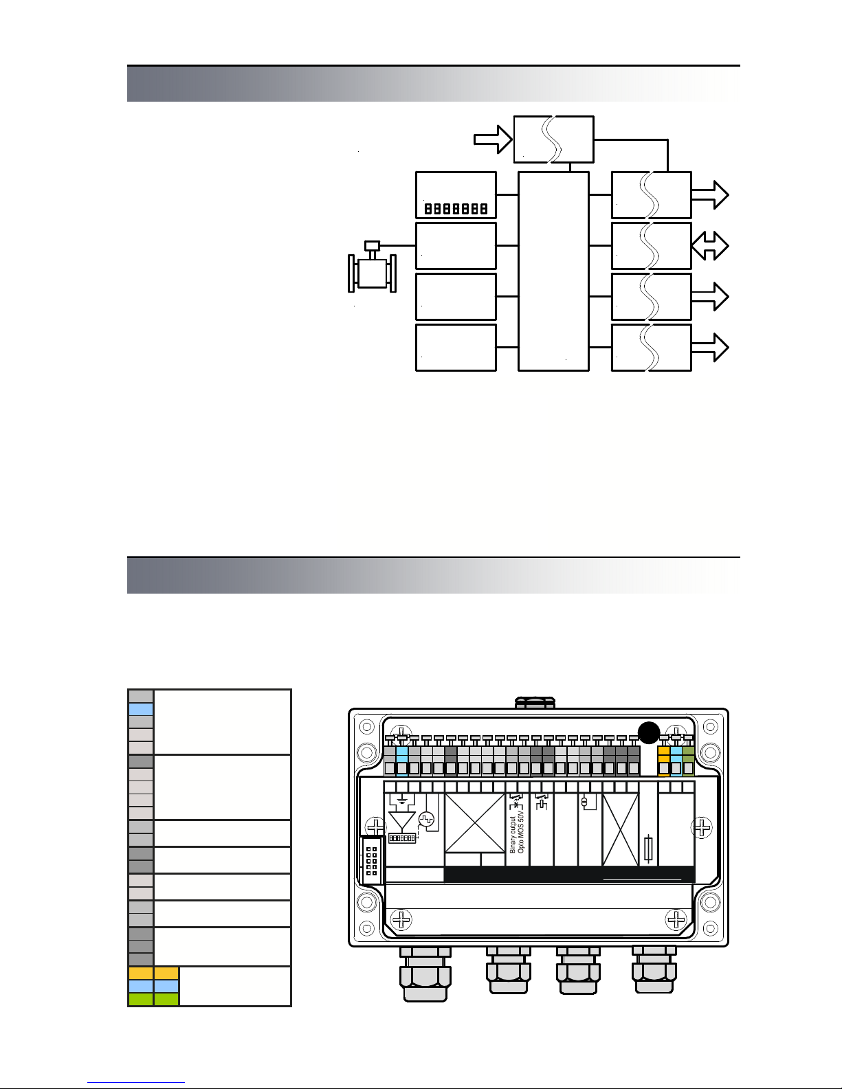
Volba výstelky snímače Block diagram of the flowmeter
Main advantage of the magnetic flowmeter FLOMAG3000
is its significant variability. Flowmeter converter in basic version
consists only of power supply,
microcomputer and sensor input module (module 1). Display,
outputs and other optional features are available as plug-in
modules. Thus, customer pays
only for features that he really
uses. Plug-in modules contain
memories where all configuration data is stored. In this way,
optional features can be added
or modified as required anytime
during the service life of the
flowmeter.
There are 4 free positions
available (module 4, 5, 6 and 7)
for binary and analog output
modules. Their signals are usually processed by connected
technological devices. All output
modules have galvanic isolation. At the same time, up to 4
binary output modules can be
fitted. These can operate either
as pulse or frequency outputs
for flow rate indication. Alterna-
Power
supply
module 4 B1
Binary output
module V1
Display
module 1 S1
Sensor input
module 2 F1
Electrode cleaning
module 5 B1
Binary output
module 6 C1
RS 232 interface
module 7 A3
Analog. output
Microcontroller
module 3 M1
Data logger
Sensor
85 - 265 VAC
(24V, 12V, AC/DC)
Fig. 19: Block diagram of the flowmeter
tively, they can serve for indication of flowmeter limit conditions. Galvanic isolation is ensured by an optoelement or a
relay. One position (module 7)
is dedicated for the active analog output module. Modules
with various accuracy and
ranges are available. One position (module 6) is designed for
the serial communication module. RS 232, RS 485 or MBus interface can be plugged
in.
Position (module 2) is for the
electrochemical electrodes
cleaning module.
A
Module 1
B
Sensor connection
C
Connected
D
internally
E
for compact version
1
module 2 F2 - F3
2
3
Not connected
4
5
6
module 4
7
A4, B1-B5, E1
8
module 5
9
A4, B1-B5, E1
10
module 6
11
A4, B1-B5, C1, D1, D2, E1
12
module 7
13
A1 - A5, B1-B5, E1
14
15
Not connected
16
17
L
18
N
Power supply
19
PE
Terminal connections
T0,5A
250V
ABCDE
12345678910111213141516PELN
B1B5C1A1
+
-
S1
V1
--
Magnetic flowmeter www.flomag.com
FLOMAG3000
Display
Sensor
connection
Relay ou
tpu
t
250VAC/
1
A
RS 232
0(4)..20mAAnalog o
utput
85 - 2
40
V
50 - 6
0 H
z
Power
T0,5A / 250V
Tab. Converter terminals Fig. 20 Converter – location of terminals
The converter is integrated in a
rugged aluminium box. After
opening the box you will gain
access to terminals. Terminals
17, 18 and 19 are for power
supply. Terminals A, B, C, D
and E are used for the sensor.
For compact version, the sensor is connected internally and
terminals remain free. Termi-
nals 1 to 16 are used for connection of inputs and outputs of
optional modules (binary outputs, current output, RS232,
RS485 etc.)
Page 8
FLOMAG 3000 -
Installation and Operation Manual
8
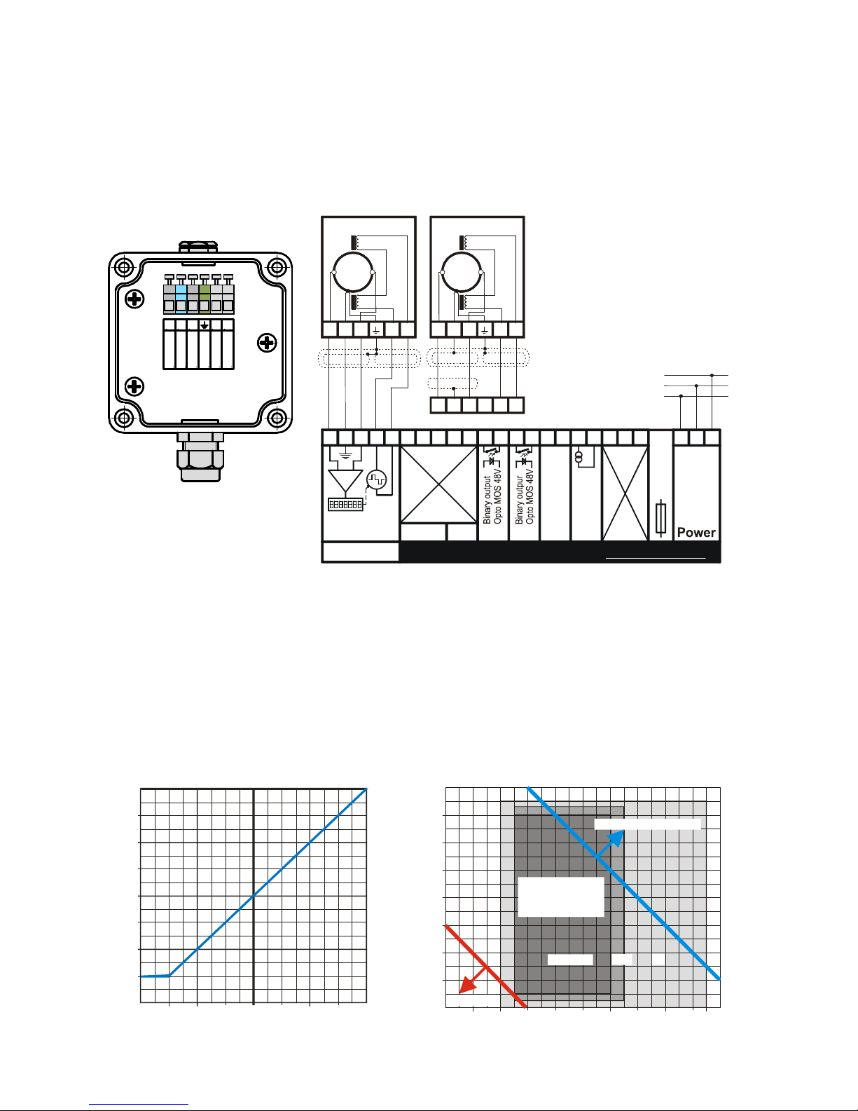
For the remote sensor, there
is a terminal box in its tapping
(see figure 21). The sensor
should be connected to the converter using a double shielded
cable. You can use our special
sensor cable PAAR-LiYCY-CY
[1X(2X0,25 LiYCY)+1X(2X0,75
LiYCY)+1X0,75]CY (length up
to 200 m) or standard double
Maximum length of the cable
between evaluation unit and the
sensor is significantly limited by
conductivity of measured fluid,
as shown in Figure 23.
Remote version should be used
when measured fluid is too hot
to avoid heat transfer to converter. See Figure 24 for assessment of remote version
utilization.
Parallel running of power and
0
25
50
100
200
0255075
100125150175200
Maximum length of cable
[ m ]
Fluid conductivity
[ S/cm ]
m
shielded cable Lapp UNITRONIC Cy PiDy 2x2x0.25 or
Alpha 1243/2C (length up to 50
m).
Fig. 21: Sensor terminal box Fig. 22: Remote sensor connection
signal wires is highly inappropriate; especially in case of the
cable that connects the sensor
with the remote converter. If the
instrument is used in environment with strong electromagnetic interference, cables
should be rather as short as
possible.
For connection of electronic
converter input and output terminals, shielded cables are suit-
able.
For connection of mains voltage, a standard three-core cable, e.g. CYKY 3x1,5 (wire) or
VM03VQ-F 3x1 (wire strand) is
recommended. The instrument
has no switch so it should be
fused and switched using other
device.
Fig. 23: Maximum length of the cable and conduc-
tivity
Fig. 24: Selection of version according to temperature
A B C D E
Yellow/Green
Yellow
Red
White
Brown
Green
AB
CDE12345678910111213141516PEL
N
B1B1C1A3
+
-
S1
V1
Magnetic flowmwter www.flomag.com
FLOMAG3000
Display
Sensor
input
RS 232
4..20mA
Analog. output
85 - 265 V
48 - 63 Hz
T0,5A / 250
V
AABBCCDDEE
PE
N
L
M1F
1
17181
9
AABBCCDDEE
Sensor
Sensor
ABCDEABCDE
Cable
PAAR-LiYCY-CY
[1X(2X0,25 LiYCY)
+1X(2X0,75 LiYCY)
+1X0,75]CY
Cable
Lapp UNITRONIC
Cy PiDy 2x2x0.25
or
Alpha 1243/2C
-20
-10
0
10
20
30
40
50
60
-60-40-20
0204080
100
120
140
160
Fluid temperature [ °C ]
Ambient temperature [ °C
]
TG, MG
NG
T
Remote version
Heating
Remote or
compact
version
Page 9
FLOMAG 3000 -
Installation and Operation Manual
9
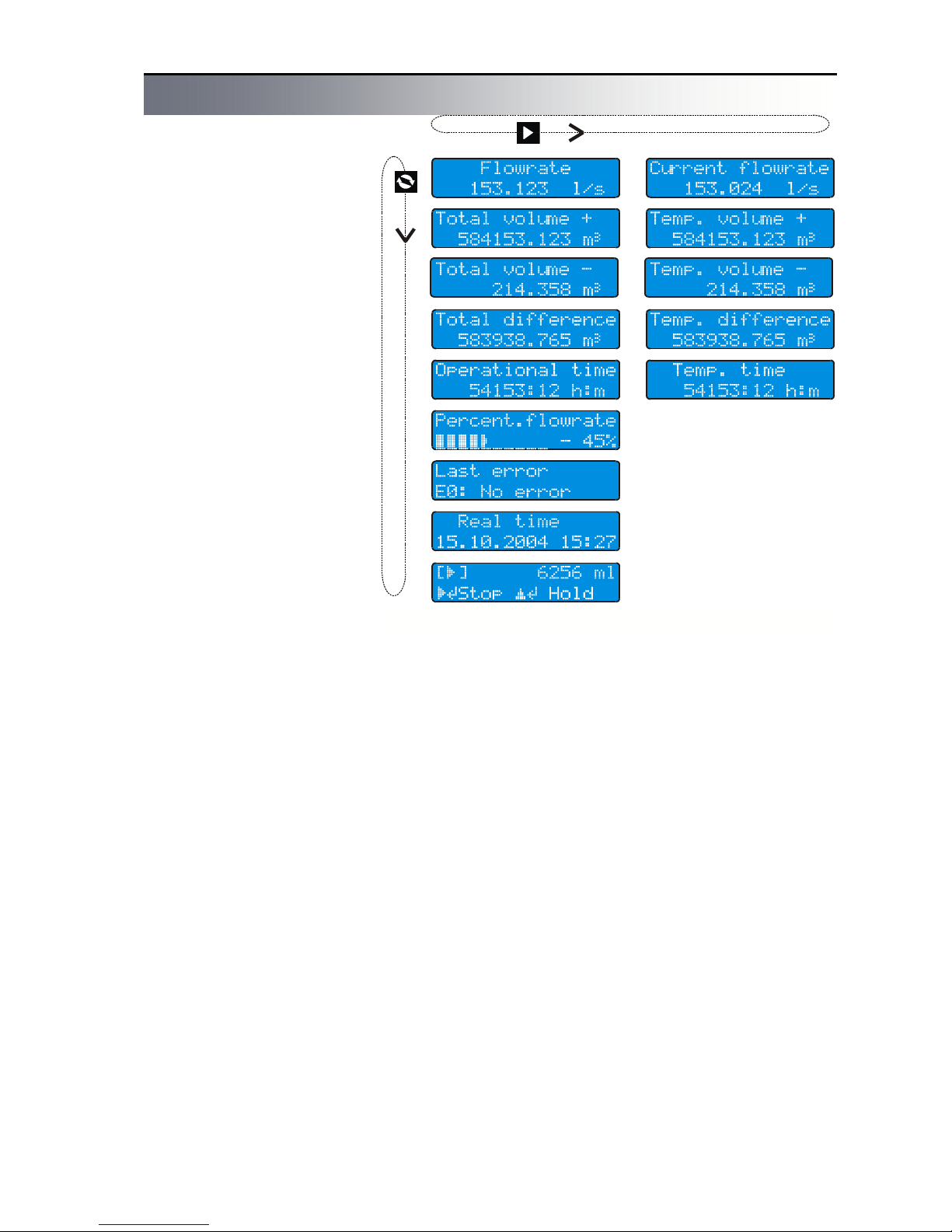
Displayed data
Fig. 25: Displayed data
The instrument is equipped with
a high quality backlit two-line
alphanumerical display with
character height 9.6 mm (2x16
characters) providing good
readability even from longer
distances. Backlight function
works in energy saving mode.
Backlight time is limited to 254
seconds after last pressing of
any key. If backlight is off,
pressing of any key will switch it
on again. Backlight time can be
set in menu from 20 seconds to
254 seconds. Setting to 0
switches backlight permanently
off; setting to 255 switches it
permanently on.
Up to 8 basic readings can be
read from the converter display.
You can alternate them using
1 key. Additional information
accessible via 2 key is avail-
able for some displayed data.
Flow rate
- Flow rate value treated by
floating averaging. Number of
averaging steps can be
changed in range from 1 to 256.
Flow rate units can be changed
as required.
Number of displayed decimal
places can be set in range from
0 to 4.
Total volume (+)
- Total volume of liquid flowed
in direction of arrow on the sensor from start of measurement.
Total volume (-)
- Total volume of liquid flowed
in opposite direction of arrow on
the sensor from start of measurement.
Volume difference
- Difference between positive
and negative volumes flowed
from start of measurement.
Operation time
- Total time of operation from
initial switching instrument on in
hours and minutes.
Percent. flow rate
- Flow rate information indicated
by horizontal bar (its width corresponds to flow rate) and as
numeric value in per cents of
chosen maximum value.
Last error
- Abbreviated text of the last
error message.
Current flow rate
- Flow rate value untreated by
floating averaging.
Temporary volume +
- User resettable value of volume flowed in direction of arrow
on the sensor.
Temporary volume -
- User resettable value of volume flowed in opposite direction of arrow on the sensor.
Temporary difference
- User resettable value of difference between volumes flowed
in direction and in opposite direction of arrow on the sensor.
Temporary time
- User resettable value of volume flowed in direction of arrow
on the sensor.
Values of temporary counters
can be reset by holding 3 key
and simultaneous pressing 4
key. This will reset all counters
at the same time – both volumes and time.
Batching
- Shows information about the
running batch. Detailed information is given in chapter Batching.
Page 10

FLOMAG 3000 -
Installation and Operation Manual
10
Archiving
Electromagnetic flowmeter
FLOMAG3000 automatically
saves in fixed time intervals ,
the value of the flowed volume.
There are three archives.
Hour archive where it is possible to find the flowed volumes
about the last 192 hours (8
days).
Daily archive where it is possible to find the flowed volumes
about the last 192 days (more
than half year).
Month archive where it is possible to find the flowed volumes
about the last 12 months.
Upper line shows always time
interval of the item in the archive. Second line shows the
flowed volume in the fixed time
interval and the power off time
in the fixed time interval (the
flowmeter was without power
supply).
Listing in archive
Pushing key 1, roll to item
Total volume+. By repeated
pushing of key 2 you can find
gradually Flow rate +, hour archive, day archive and month
archive.
By repeated pushing of key
3, in the hour archive you can
see gradually the saved sam-
ples from the previous hour,
totally 192 hours back.
By repeated pushing of key
3, in the daily archive you can
see gradually the saved sam-
ples from the previous day, totally 192 days back.
By repeated pushing of key
3, in the month archive you
can see gradually the saved
samples from the previous
month, totally 12 months back.
If you want to go back to the
last saved sample, please push
and hold key 3 and together
with it push key 4.
Fig. Hour archive
Fig. Daily archive
Fig. Month archive
Fig. Legend
Fig. Hour archive moving
Fig. Daily archive moving
Fig. Month archive moving
Ok - without power off
-#s - power off time in secunds
-#m - power off time in minutes
-#h - power off time in hours
-#d - power off time in days
Error messages
Fig. Error messages
In case of a fault, an error
message with short description of the fault is
shown immediately at the
LCD.
The error message begins
with character E followed
by error's number. If the
error is connected with a
defect of a module than it is
followed also by character
M and the number of the
module. After pushing but-
ton 1 the flowmeter returns to value display mode
and at the same time the error message is saved to last
error register. During the indication of the error message,
the flowmeter is measuring.
In case of error E-7, E-8 and E
-13, the flowmeter indicates 0
if the mentioned error message is not forbidden in the
menu.
Error messages are listed
below together with recommendation how to repair.
E0: No error
E1: EEPROM Checksum
error
Checksum error saved in
the module - re-check data
in the module and save
again
E2: Stack overflow
For module „B“ in pulse
mode - the time constants
are too long, the flow rate is
higher than it is possible to
send pulses, stack overflow
of un-sent pulses - change
pulse length and space
length or volume for 1 pulse
E3: Frequency limit ex-
ceeded
For module „B“ in frequency mode, it is required
higher output frequency than
the module is able to send,
flow rate is higher than it
was assumed - set higher
flow rate value for 1kHz.
E4: Power fail
Page 11

FLOMAG 3000 -
Installation and Operation Manual
11
Appears for short after
power fail
E5: Old software
For proper operation of the
module is required newer
firmware version than it is
installed in the convertor –
upgrade firmware.
E6: Can't use this mode
For module B placed in
position 6 and 7 is not possible to use frequence mode
(it is possible only in position
4 and 5) – change the position of the module or change
the mode to pulse.
E7: Sensor loop disconnected
No current to the coils – for
remote version check cables
and terminals
E8: Empty pipe
For modules F2 and F3,
indicates that the controlling
electrode is not submerged
E9: Low medium conductiv-
ity
For modules F1 and F3 in
electrodes cleaning mode,
no current in the electrodes,
sensor is not submerged,
electrodes are furred or low
medium conductivity - clean
the sensor
E10: MBus conflict
Module D3 – exist two stations M-Bus with same address – change the setting of
module D3
E11: Current output
overrange
For module A it is required
higher output current than
20mA, flowrate is higher
than it was assumed – set
higher flow rate value for
Imax
E12: Serial line fail -
communication error
Communication module
C1 or Dx sends data but
does not receive confirmation for receipt of data –
check cables, could be
caused also by external interference, high capacity of
the cables or too long cables.
E13: Sensor signal over-
range
Signal from the sensor is
overrange of the convertor electrodes are not submerged or there is short circuit of the cables – check
the sensor and the cables
User outputs – plug-in modules
T0,5A
250V
position 8
position 1
position 2
position 3
position 4
position 5
position 6
position 7
Flowmeter converter in basic
configuration contains the
power supply and boards required for measurement functions. All other inputs, outputs
and display units can be added
as plug-in modules. Customer
pays only for features that he
really uses. At the same time,
this concept allows using of
various types of inputs and outputs tailored to customer needs.
Following table and figure
indicate positions and functions
of individual modules.
Fig. Module positions
Tab. Module positions
Positio
n
Modules
Terminals
1
S1 sensor input
module, always
plugged in
A, B, C,
D, E
2
F1-F3 module for
sensor full pipe
checking and electrode cleaning
1, 2, 3,
4,
5,
3
M1 extended memory
module of measured
data
-
4
A4,A7 passive cur-
rent output 4 - 20 mA
B1-B5 binary outputs
incl. frequency up to
12 kHz
E1 binary input
6, 7
5
A4, A7 passive cur-
rent output 4 - 20 mA
B1-B5 binary outputs
incl. frequency up to
1,2 kHz
E1 binary input
8, 9
6
A4, A7 passive c.o.
B1-B5 except for
frequencies,
C1, D1, D2, D3, G1,
H1 data communica-
tion
E1 binary input
10, 11
7 A1-A3, A5, A6 active
current output
A4, A7 passive c.o.
B1-B5 except for
Frequencies
E1 binary input
12, 13
8
V1 display and key-
pad
10 pin
connector
Page 12

FLOMAG 3000 -
Installation and Operation Manual
12
Parameter setting
The magnetic flowmeter converter can be configured in two
ways, as required: either using
a PC connected via serial interface, or using keys.
Press 4 to switch the display
to programming mode. Programming mode is password
protected against unauthorized
access. Correct password (4digit number) must be entered
to obtain access to main menu.
Password of a new instrument
is always set to 0000.
Fig. Enter password
This is also initial value displayed as default. Simply confirm it to enter in menu.
Password can be changed as
required before you leave the
programming mode.
Warning! You can switch the
instrument to data display mode
anytime by pressing 1 and
check current parameter settings. However, the instrument
is not password protected
against unauthorized access
until you enter EXIT command.
Programming runs in background and with only a few exceptions has no influence to
measurement.
Fig. Cursor movement
2 key moves cursor to the
right. When the utmost right
position is reached, the cursor
returns to the left.
Fig. Character changing
system returns to the first available character.
Character set is always selected with regard to possibility
of character occurrence in text:
[0..9] for integers, [0..9,- , .] for
decimals and complete alphabet for text variables (including
Czech characters).
Confirm your selection by 4
key to finish editing.
A status message will be displayed. If your password is not
accepted, program returns to
editing mode. If correct password was entered, you will get
to main menu.
Use 3 to move in menu. This
key moves the lower line item to
upper line. In all menus, the
upper line with blinking first
character is always the active
line.
Press 4 to enter in submenu
or to edit item. Pressing 2
in submenu brings you always
back to previous menu
(“Escape” function). If you are in
main menu, pressing of this key
will offer exit from programming
mode.
Menu legend
Some menu items can be
used only for viewing and do
not allow change of values.
Fig. Movement in menu
Fig. Status message
+ Noise filter
+ Dynamic filter
» Enter password
○ 125 mA
● 250 mA
¤ Production date
3 key changes character at
cursor position. When the last
available character is reached,
Fig. Read only
Fig. Enter value
Press 4 to return to previous
menu.
Other menu items can be
used to enter value directly.
When you enter the value and
press 4, a status message will
be displayed.
If the value entered is accepted, press any key to return
to previous menu or to edit next
item.
If the value entered is out of
range, an error message will be
displayed; press any key to edit
the value.
In some cases, one of listed
values has to be selected.
Fig. Selection of one value
Use 3 to select required item.
When the required value is in
the upper line, press 4 to con-
firm your selection. A status
message will be displayed to
confirm that your selection has
been accepted. Press any key
to return to previous menu or to
edit next item.
In some cases, more of listed
values can be selected.
Fig. Selection of more items
There is a sign “+” (indicating
that the item is selected) or ““ (indicating that the item is not
selected) before each of items.
Fig. Selection of more items
Press 2 to change selection
for the item displayed in the
upper line. Press 4 to finish
your selection. A status message will be displayed to confirm that your selection has
been accepted. Press any key
to return to previous menu.
Page 13

FLOMAG 3000 -
Installation and Operation Manual
13
Flowmeter menu
» Enter password
↓
0.Production data → Production date → ¤ Production date
Serial number → ¤ Serial number
Software → ¤ Software
Meter's type → ¤ Meter's type
Modules used → ¤ Embeded modules
Date setting → » Date
Time setting → » Time
Permit upgrade → » Upgrade PIN
Delete history → » Delete PIN
Reset volumes → » Reset PIN
1.Sensor → Sensor constants → Constatnt 1 → » Sensor constant1
Constant 2 → » Sensor constant2
Excitation freq. →○ 2.775 Hz
● 3.125 Hz
○ 5.55 Hz
○ 6.66 Hz
○ 12.5 Hz
○ 25 Hz
Excitation curr. →○ 125 mA
● 250 mA
Supressed flow → » Do not meas. Q<
Samples → » Samples
Filters →√ Noise filter
√ Dynamic filter
Zero setting → » Autozero PIN
2.Module 2 → Specific settings for individual modules
…
7.Module 7 → Specific settings for individual modules
8.Display → Language →● [CZ] Česky
○ [D] Deutsch
○ [GB] English
○ [PL] Polski
○ [I] Italiano
○ [NL] Nederlands
○ [S] Svenska
○ [E] Espanol
○ [F] Francais
100 per cent → » 100 per cent
Flowrate units →● l/s
…
○ m3/h
…
○ User's → » Flowrate multipl
» Unit's name
Decimal places → » Decimal places
Backlight → » Backlight time
Display select →√ Flowrate
√ Total volume +
√ Total volume +
√ Total difference
√ Operation time
√ Percent flowrate
√ Last error
√ Real time
Error messages →√ E1
√ …
√ E13
9.Exit → Exit menu
Exit menu
New password → » Access password
Page 14

FLOMAG 3000 -
Installation and Operation Manual
14
0. Production data
This submenu relates to the
flowmeter converter.
·Production date – of con-
verter
·Serial number – of con-
verter
·Software – current soft-
ware version
·Type of meter – type num-
ber of flowmeter converter
·Modules used – types of
currently used modules
(Above listed items are only for
information and user cannot
change them)
·Date setting – setting of
current date
·Time setting – setting of
current time
·Upgrade enabled – a new
firmware version can be
uploaded after entering PIN
·Delete history – archives
will be deleted after entering
PIN
·Reset volumes – All total-
izers will be reset after entering PIN
1. Sensor
This submenu relates to the
sensor.
·Sensor constants – sen-
sor calibration constants
·Excitation frequency – of
sensor coils
·Excitation current – of
sensor coils
·Suppressed flow rate –
when flow rate is lower than
this value, it is considered
for zero. This setting is used
to suppress creeping flows.
·Number of samples – for
floating averaging that filters
measured flow rate value.
Higher number of samples
provides more stable flow
rate value, however it increases time constant and
causes delayed reaction to
flow rate changes.
·Filters
¨Noise filter partially re-
duces jump changes but
mainly removes lower periodical interference. Transient edges are rounded as
can be seen in figure of response to unit jump. The
filter is applied already on
input and thus influences
immediate flow rate value
and cumulated volume calculated from it. The noise
filter introduces only negligi-
ble delay (about 0.3 sec)
and can be used almost at
all circumstances.
¨Dynamic filter reduces
rapid jump changes of flow
rate. It protects very effectively against high short
peaks caused by interference. Unlike averaging, dynamic filter cuts input signal
and interference is not included in cumulated volume. It can however cause
delay of flow rate jump
change indication. This fact
should be considered if the
flowmeter is used for dosing
applications. Response to
unit jump can be seen in
figure.
8. Display
This submenu relates to data
shown on the display.
·Language – language of
displayed data. You can
select from 9 languages.
·100 per cent – 100 % flow
rate for bar diagram. It is
Fig. Dynamic filter
Fig. Noise filter
used only for percentage
bar diagram display; it is not
meant as range of the meter.
·Flow rate units – You can
select from 12 preset units
or add your own user defined unit. In such case you
have to enter multiple of
flow rate in l/s and a unit
name.
·Decimal places – Number
of decimal places of displayed flow rate. You can
enter 0-4 decimal places. If
5 places are entered, number of decimal places will be
dynamically changed to 4
valid decimal places.
·Time of backlight – Time
of display backlight in seconds. When you press any
key, backlight of display
goes on. When time period
set in seconds expires since
you pressed the last key,
the backlight goes off. You
can set time period from 1
to 254 seconds. If you set 0,
backlight will never be on. If
you set 255, the display will
be permanently backlit.
·Displayed values – De-
fines what items will be displayed. You can select any
of available items. These
will be alternately displayed
on the flowmeter display.
Press 1 to alternate displayed values.
·Error messages – Enable
or disable displaying of individual error messages.
9. Exit
·Exit menu – When you
finish editing, you have to
exit menu because only after that settings are permanently stored in module
memories. If you will not exit
the menu and power failure
occurs, previously entered
settings will be loaded. Also
access to menu is password
protected only when you
exit menu.
·New password – You can
change the access password before you finish your
editing.
Time
NtN
Sampling moments
Current flow rate
Flow rate
Average flow rate
Fig. Averaging
Page 15

FLOMAG 3000 -
Installation and Operation Manual
15
Modules A – analog current
output – are used for flow data
transmission. There are 4 different types available with various
ranges, accuracy and functions.
Outputs of A1 to A3, A5 and
A6 modules are active (forced
current) and are galvanically
isolated from other flowmeter
parts. Outputs can be loaded up
to 1000 Ω. They can be plugged
only in position 7.
A4 and A7 modules have passive current output (it has to be
powered externally) and are
also galvanically isolated.
Unlike A1-A3, A5, A6 modules,
it can be plugged in positions 4,
5 and 6.
0..+Q output
0..-Q output
IQI output
-Q..+Q output
Fixed current 0..20
Depending on flow rate (see
diagrams), output can work in 5
modes:
The first four modes generate
output current dependent on
flow rate, the fifth mode enables
direct entering of current. Following 4 ranges can be selected for all modes (except for
the fixed current mode):
A3, A4, A6 and A7 modules can
work only with range 4..20 mA.
0..20mA output
4..20mA output
0..10mA output
0..5mA output
Range
4..20mA 0..10mA 0..5mA
Flow rate / current
-Q
max
0 Q
max -Qmax
0 Q
max -Qmax
0 Q
max -Qmax
0 Q
max
0..+Q output 0 0 20 4 4 20 0 0 10 0 0 5
0..-Q output 20 0 0 20 4 4 10 0 0 5 0 0
0..IQI output 20 0 20 20 4 20 10 0 10 5 0 5
-Q.+Q output 0 10 20 4 12 20 0 5 10 0 2,5 5
0..20mA
A1
Range 0(4)..20 mA
Resolution 12 bit
Accuracy ± 0.2%, ± 0.2mA
Active - replaced by A5
A2
Range 0(4)..20 mA
Resolution 16 bit
Accuracy ± 0.1%, ± 0.1mA
Active - replaced by A5
A3
Range 4..20 mA
Resolution 16 bit
Accuracy ± 0.1%, ± 0.1mA
Active - replaced by A6
A4
Range 4..20 mA
Resolution 16 bit
Accuracy ± 0.1%, ± 0.1mA
Passive - replaced by A7
A5
Range 0(4)..20 mA
Resolution 16 bit
Accuracy ± 0.1%, ± 0.1mA
Active
A6
Range 4..20 mA res. 16 bit
Accuracy ± 0.1%, ± 0.1mA
Active - compatible with
module H1 ( HART )
A7
Range 4..20 mA res. 16 bit
Accuracy ± 0.1%, ± 0.1mA
Passive - compatible with
module H1 ( HART )
Current output modules A1 – A4
Fig. 0..+Q output
Fig. 0..+Q output
Fig. IQI output
Fig. -Q..+Q output
Fig. Menu structure of A modules
7.Current output →● 0..+Q output ○ 0..20mA output»Imax flowrate
○ 0..-Q output ● 4..20mA output
○ 0..|Q| output ○ 0..10mA output
○ -Q..+Q output ○ 0..5 mA output
○ Fixed current»Fixed current [mA]
1213
A5
0..20 mA
Current output
+
-
A
+
-
1011
A7
4..20 mA
Current output
+
-
A
+
+
-
Modules A6 and A7 enables
with module H1 (Bell 202 modem) to communicate through
current loop with a protocol
compatable with HART (only
Universal Commands)
Page 16

FLOMAG 3000 -
Installation and Operation Manual
16
B1
Passive (max 4 kHz)
Max. voltage 350 V
p-p
Max. perm. current 120 mA
Max. pulse current 300 mA
Resistance 27 Ω
B2
Passive (max 12 kHz)
Max. voltage 60 V
p-p
Max. perm. current 300 mA
Max. pulse current 500 mA
Resistance 5 Ω
B3
Active
Voltage 5 V
Max. current 10 mA
Max. frequency 12 kHz
B4
Active
Voltage 24 V
Max. current 40 mA
Max. frequency 12 kHz
B5
Relay contacts
Max. voltage 250 VAC
Max. current 1 A
Binary output modules B1 - B5
Flowmeter converter can control up to 4 multifunctional binary outputs in positions 4 – 7.
Following table indicates differences between individual modules:
Outputs can work as pulse,
frequency or status outputs.
Individual functions are explained in detail in following
section.
Binary module functions
· Normally closed/open
These modes are used for service purposes.
· Pulse outputs (not)
In this mode, a pulse is generated immediately after preset
volume has flowed. Pulse generation is determined by three
factors: pulse length “tu”, mini-
Tab. Binary output modules
mal delay between two pulses
“tD” and volume per pulse “V”.
Flow rate values are time integrated. Immediately after preset
volume per pulse has flowed,
the pulse of length tu is generated. After the pulse, there is a
delay of length at least tD. If the
delay expires and the preset
volume has not flowed again,
the output remains inactive;
otherwise, another pulse and
delay are generated immediately. If the preset volume flows
through sooner than the previous pulse is finished, the unsent
pulse will be stored in a buffer
with maximum capacity of 255
pulses. If buffer overflow occurs, an error message will be
generated. It follows from above
mentioned that parameters of
pulse output should be set such
that expected pulse frequency
cannot exceed limit frequency
determined by pulse length and
delay.
It applies: Maximum pulse
frequency [s-1] = 1 / (tu + tD)
Volume per pulse can be set in
range from 1 to 109 ml with 1 ml
step, i.e. from 1 ml to 1000 m3.
Delay and pulse lengths can be
set in range form 10 ms to 2550
ms with 10 ms step. It follows
from above mentioned that the
maximum pulse frequency is 50
s-1.
Pulses can be generated in
three modes depending on flow
rate, and pulse polarity can be
set (output is closed during
pulse or open in not modes).
Fig. Pulse generation
Fig. IQI pulses
Fig. Q+ pulses
Fig. Q- pulses
· Frequency outputs
In this mode of operation, frequency is generated on output
modules. Pulse to delay ratio is
always 1:1. Warning! Only two
frequency generators in positions 4 and 5 are available for
the converter. This function is
blocked in positions 6 and 7.
Maximum frequency in position
4 is 12 kHz and in position 5
only 1.2 kHz. If these limit frequencies are exceeded, output
frequency will be limited and an
error message will be generated.
Frequency outputs can work in
three modes of frequency dependence on flow rate.
Setting is done by selecting of
flow rate corresponding to 1
kHz output frequency.
Fig. Q+ frequency
Fig. Q- frequency
Fig. IQI frequency
Page 17

FLOMAG 3000 -
Installation and Operation Manual
17
Fixed frequency mode is used
for service purposes. Required
frequency is set directly in Hz in
range 1-120000 Hz in position 4
and 1-1200 Hz in position 5.
· Negative/non-negative
flow rate
This mode is used for flow direction differentiation. Output is
closed/open for negative flow
rate.
· Failure occurred/not oc-
curred
If failure with mode set to active
(see error messages) occurs,
the output closes/opens for at
least 5 seconds. If failure persists, output is closed/open for
whole period of failure duration.
· Limit flow rate exceeded/
undergone (not)
If flow rate is higher/lower than
limit value set, the output closes
(opens). When flow rate returns
to limits, the output opens
(closes) again taking in account
preset hysteresis. This function
Fig. Q > Qlimit
Fig. Q < Qlimit
Fig. IQI > Qlimit
Fig. IQI < Qlimit
Fig. Menu structure of B modules
Fig. Terminal connection
6
7
B1
Bi nar y o utput
Opt oMOS 35 0V
8
9
B2
Bi nar y out pu t
ac tiv e 5V/ 100mA
+
-
8
9
B5
Bi nar y out pu t
Re lay
4.Binary output ─►● Permanently open
○ Perm. Closed
○ IQI pulses » Pulse length [10ms]
○ IQI not pulses » Pause length [10ms]
○ Q+ pulses » Vol./ pulse [ml]
○ Q+ not pulses
○ Q- pulses
○ Q- not pulses
○ Q+ frequency » Flowrate at 1 kHz
○ Q- frequency
○ IQI frequency
○ Fixed frequency » Fixed frequency [ Hz ]
○ Negative flow
○ Non-neg. flow
○ 'Error occured √ E1
○ 'No error occured √ …
√ E13
○ Q>Qlim. » Flow limit
○ Q>Qlim. not » Hysteresis
○ Q<Qlim.
○ Q<Qlim. not
○ IQI>Qlim.
○ IQI>Qlim. not
○ IQI<Qlim.
○ IQI<Qlim. not
○ Cleaning
○ Not cleanig
○ Batch Opened » Volume Advance [ml]
○ Batch Opened not » Time Advance [ms]
○ Batch Stop puls » Pulse length [10ms]
○ Batch Stop /puls » Volume Advance [ml]
» Time Advance [ms]
works in four modes of dependence on flow rate with output
polarity differentiation.
· Electrode cleaning/no
cleaning
The output is closed/open during cleaning.
· Batch Opened
· Batch /Opened
Output is switched on /
switched off during the batch
running. It is possible to set the
advance of the output before
batch ending. Advance could be
set by time or volume. Detailed
information is given in chapter
Batching.
· Batch Stop pulse
· Batch Stop /pulse
Output generates pulse for
ending of the batch. It is possible to set pulse length (10ms 2,5s) and pulse advance before
batch ending. Advance could be
set by time or volume. Detailed
information is given in chapter
Batching.
Page 18

FLOMAG 3000 -
Installation and Operation Manual
18
C1, D1, D2 and D3 modules
Modules C1, D1, D2 and D3
are used for data communication. All these modules are galvanically isolated from flowmeter circuits. They can be installed only in position 6 and
their signals are output to terminals 10 and 11. Interface
RS232 is the only exception, as
it needs 3 wires.
C1 – RS232 interface
It is used primarily for
service purposes, because maximum cable
length from the converter
to a computer is 15 meters and only one converter can be connected
to a single link.
Connection to the computer equipped with RS232 interface is done using an included cable. Thread one end
of the cable through a cable
bushing and connect it to 3-pin
connector behind terminals 10-
11. The other end of the cable
is equipped with CANON 9M
connector. This ensures leading
of RS232 interface signals out
of converter box while protection level IP66 is maintained.
The interface is connected to
the computer using a crosslink
cable Laplink 9F-9F.
D1 – RS485 interface
It is used for permanent connection of multiple converters to
the computer. It enables con-
C1
RS232
D1
RS485 (MODBUS)
D2
0/20mA data current loop
D3
M-BUS
G1
GSM modem
H1
HART modem (with A6,7)
12345
6789
CANON 9F
12345
6789
CANON 9M
1011
C1
RS 232
Fig.RS232 cable connection
necting of up to 31 stations in a
communication network using a
twisted pair link cable with total
length of 1200 meters. Number
of stations and length of cables
can be increased by using re-
peaters. Stations are connected
to the link in parallel. The most
distant ends of line have to be
equipped with terminating resistors 120 Ω.
When setting stations, be
sure to set the same baud rate
for all of them and to set a
unique address for each of
them. MASTER address is always set to “0” and addresses
of individual stations can be set
in range 1-254.
D2 – Data current loop
interface 0/20 mA
It is used for permanent connection of multiple converters to
the computer. It enables connecting of multiple stations on
long distances. Data transfer
via current coding 0/20 mA is
highly resistant against interference and is suitable for indus-
Fig. RS485 network connection
Fig.Data current loop 0/20 mA
network connection
trial environment. Individual stations are connected in series.
Disadvantage of this configuration is that if one station fails,
then whole network breaks
down.
D3 – M-BUS interface
Standard M-Bus (Meter-Bus)
is designed for applications of
data acquisition from various
media consumption meters. It
enables connecting of many
devices (hundreds of them) on
distance of several kilometers.
Fig. M-Bus network connection
Fig. Communication module menu
M-BUS
DEVICE 1
DEVICE 2
DEVICE
3
M-BUS
M-BUS
M-BUS
MASTER
10
1110111011
6.RS232 ─► Baudrate ─►○ 300 Bd
○ 600 Bd
○ 1200 Bd
○ 2400 Bd
○ 4800 Bd
● 9600 Bd
○ 19200 Bd
○ 38400 Bd
○ 57600 Bd
○ 76800 Bd
○ 115200 Bd
Adress ─► »Own adress
Protocol ─►● FLOMAG
○ M-BUS
○ MODBUS-RTU
○ MODBUS-ASCII
○ HART
Parity ─►● No parity
○ Odd parity
○ Even parity
Word order ─►● Low word first
○ High word first
Page 19

FLOMAG 3000 -
Installation and Operation Manual
19
Modul E1
Module E1 is galvanically
separated active binary input for
nonvolatile contacts or open
collector. Input has SW transient immunity. It is necessary
min pulse length of 60 ms for
switching .
Functions of the binary
input
· Switch Off
· Batch Start
Starts the batch (see section
Batching).
· Batch Hold
Stops and holds the batch.
Counted batch can be continued after restarting it (see section Batching).
· Batch Stop
Asynchronously finishes the
batch and sets again the preset
batch volume (see section
Batching).
· Reset Volumes
Enables reset of the chosen
totalizers and working time.
· Cleaning Start
Starts electrochemical electrodes cleaning in modules F1
or F3 (requires plug-in modules
Fig Menu of module E1 Fig. Terminal connection
2. Electrode cleaning
─►
● OFF
○ Only once
○ During Power ON
○ Periodiccally
─►
»Clean every x [h]
»Time of start [h:m]
F1, F2 and F3 modules
F1 – F3 modules are used for
full pipe check and for electrochemical cleaning of electrodes.
F1-Electrochemical
electrode cleaning mod-
ule
During operation of the flowmeter, a non-conductive layer
can be formed on sensor electrodes. This layer increases
contact resistance between
electrodes and measured fluid
and results in lower measurement accuracy.
F1 module enables measuring electrode cleaning without
need of sensor deinstallation.
The method is based on electrochemical effect. Alternating
voltage is connected to electrodes and the deposited layer
dissolves in liquid. This cleaning
should be performed periodi-
F1
Electrochemical electrode cleaning module
F2
Empty pipe detection
module
F3
Module with combined
functions F1+F2
cally.
The cleaning cycle takes 1
minute. During cleaning, no real
measurement is performed.
Flow rate measured before start
of cleaning is simulated. Cleaning cycle duration can be indicated using binary outputs.
Running cleaning process is
indicated on display by moving
full character on upper line.
The instrument offers several
possibilities of cleaning cycle
start:
If ONCE is selected, a single
cleaning cycle is immediately
performed and then the instrument returns to Off mode.
If AFTER SWITCH-ON is selected, the cleaning cycle will be
always started if power supply
is switched on. Option PERIODIC starts cleaning in regular
intervals that can be set by user
in range from 1 to 255 hours.
Timer starts counting after time
value is entered. Starting time
of cleaning can be set to match
to real time. It makes sense
only if cleaning period is set in
multiples of 24 hours. Then
cleaning will be performed always in preset time. F1 module
has no wires connected to the
terminal block.
F2 - Full pipe check
module
Correct measurement of flow
rate by the magnetic flowmeter
is conditioned by full flooding of
the whole sensor cross section
by measured liquid. If flooding
is only partial, the magnetic
flowmeter will indicate flow rate
higher than real. However, if
both electrodes are not immersed in liquid, interfering voltage can be generated on elec-
OFF
Only once
During power ON
Periodically
Fig. F1 module menu
4. Binary input ─►● Off
○ Batch Start
○ Batch Hold
○ Batch Stop
○ Reset Counters
─►
√ Total volume +
○ Cleaning Start
√ Total volume -
√ Operational time
√ Temp. volume +
√ Temp. volume -
√ Temporary time
Page 20

FLOMAG 3000 -
Installation and Operation Manual
20
trode wires and the flowmeter
can indicate totally random values. To avoid this situation, the
sensor can be equipped with
checking electrode and converter with full pipe check module. The module continuously
checks if the checking electrode
is immersed in liquid. If it is not,
an error message will be displayed and zero flow rate will be
indicated. The checking electrode is connected to terminal 1.
This electrode cannot be retro-
fitted and should be considered on initial order.
Fig. F2 module menu
F3 - Electrode cleaning
and full pipe check module
This module combines functions of modules F1 and F2.
Besides different menu, all
above mentioned information
applies for this module.
Fig. F3 module menu
2. Full pipe check
─►
√ ON
2. Clean/Full pipe
─►
Electrode cleaning
─►
● Off
○ Once
○ During Power ON
○ Periodiccally
─►
»Clean every x [h]
»Time of start [h:m]
Full pipe check
─►
√ ON
Batching
Batching mode is used for
control of external equipment
( valves, pumps) in order to
measure repeatedly the preset
volume (batch). It is not recommended for batching of very
small volumes. The period of
one batch has to be min 30 s.
Electromagnetic flowmeter
FLOMAG3000 has very sophisticated batching functions. It
enables simple batching with
manual starting but also fully
automatic batching by remote
control.
Batching process is divided
into 4 phases. Single phases
are distinguished on LCD by a
symbol in square brackets. Upper line shows remaining volume in ml to the end of the
batch. Bottom line shows help
for manual batch control.
Phase 0 - Stop
During phase 0 outputs are
inactive, no batching runs, waiting for start of the batching
process. Manual start is real-
ized by holding button 3 and
simultaneous pushing of button
4 or from outside with the help
of module E in Batch Start
mode. During that phase the
batch volume is set. To enter
edit mode it is necessary to
hold button 2 and simultaneously push button 4.
Phase 1 - Hold
Phase 1 temporary batch in-
terruption. Outputs give signal
for interruption of the batch
(close valve, switch off pump).
Counted batch could ve continued again by manual start
choosing Restart or from outside with the help of module E
in Batch Start mode. It is possible also to abort the batch by
choosing Reset or from outside
with the help of module E in
Batch Stop mode.
Phase 2 - Run
During that phase runs the
measuring of the batch (valve is
open, pump is running). This
mode can be interrupted using
Phase 1 (Hold) activated manually or with the help of module E
in Batch Stop mode. It is possible also to abort it choosing Re-
Fig. Batching phase 0
Fig. Batching phase 1
Fig. Batching phase 2
Module G1
Module H1
Module G1 is a GSM modem
enabling sending by SMS messages on preset numbers, in
preselect intervals (or on re-
quest) inforamtion about the
status of the flowmeter and the
measured values. Detailed description of the module func-
tions is given in a separate
document.
Module H1 is Bell 202 modem, extensioning the function
of modules A6 and A7. It enables data communication
through current loop with a pro-
tocol compatible with HART
(only Universal Command). Assigning the variables of the
flowmeter is following:
PV - Flow rate [ l/s ]
SV - Current flow rate [ l/s ]
TV - Total volume + [ m3/h ]
QV - Total volume - [ m3/h ]
Page 21
FLOMAG 3000 -
Installation and Operation Manual
21
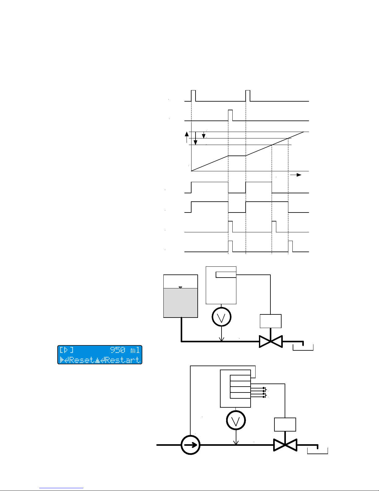
Fig. Batching phase 3
Fig. Batch running
Fig. Minimum batching option
Fig. More complex batching option
event which first takes place.
The advantage is that you can
set different advance for each
output. This way it is possible to
switch off a pump and later
close the valve.
Binary outputs have 4 options
for setting in batch mode. They
set or from outside with the
help of module E in Batch Stop
mode. During this phase there
is no reaction to external signal
Batch Start. If there is no any
preset outputs' advance, after
flowing of the set batch volume
comes switching to phase 0
(Stop). Outputs will send signal
for batch stop (switch off pump,
close valve). Because of the
late reaction to the output signal
a partial overflow of the set
batch volume will take place
and display will show negative
volume. That's why it is suitable
to send a signal for batch stop
in advance as it is described
below.
Phase 3 - Finish
In practice we need to send a
signal for batch stop in advance. It is mainly because of
the inertia of the technical
equipment (valves, pumps).
Phase 3 represents time when
one of the outputs have sent in
advance signal for batch stop.
According to the ability to forecast exactly the advance, the
batch can slightly overflow
which means to go to phase 0
or the batch will not finish and
will go to phase 3. In this case it
is possible to go to phase 0 by
choosing Reset or from outside
with the help of module E in
Batch Stop mode. In the same
time takes place presetting of
the volume batch accroding to
the preset value. Second possibility is to start new batch
choosing restart or from outside
with the help of module E in
Batch Start mode.
The binary outputs in batch
mode enable setting of the advance by volume when the output is activated, if the remaining
batch volume is smaller than
the preset volume advance.
Second possibility is to set time
advance when the flowmeter's
logic calculates what time remains to the end of the batch
according to the actual flow.
Both possibilites can be combined. Output reacts to the
time
volume
output 1
output 2
output 2 (puls)
output 1 (puls)
start
hold
volume - advance 2
volume - advance 1
volume of batch
Flowmeter
Electrically
controled
valve
module B
FLOMAG3000
Pump
Flowmeter
Electrically
controled
valve
module B
module B
module E
module E
FLOMAG3000
Start
Hold
can indicate condition when
runs the batch (phase 2) or to
sent a pulse for batch finish/
interuption. Pulse length can be
set from 10 ms up to 2550 ms,
step 10 ms. Both output modes
can work in both polarities.
Page 22
FLOMAG 3000 -
Installation and Operation Manual
22
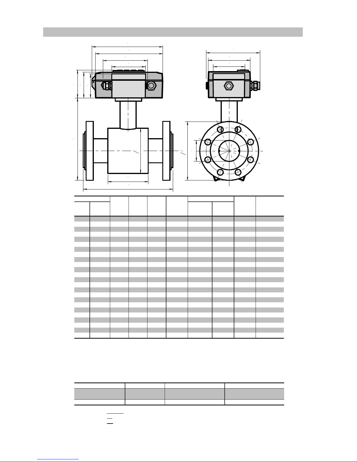
L
A
DN
o D
o d
l
160
168
80
114
58
65
70
75
100
136
* Standard construction length meets ISO 13359, different construction lengths should be indicated, e.g.
“l=215”
Construction length tolerance for DN£200: +0/-2 mm
DN³200: +0/-3 mm
** Weight of PDIN sensor without converter and terminal box
- weight of terminal box has to be added for remote version – 0.25 kg
- weight of converter has to be added for compact version – 0.9 kg
Flowmeter dimensions – flanged versions “P”, “PDIN” and “PANSI”
DN PN D d A l Weight**
ISO 13359
EN 14154
Optional
[mm] [inches] [mm] [mm] [ kg ]
15 1/2
16 95 62 164 200 138 66 3.5
20 3/4
16 105 62 170 200 138 66 3.5
25 1
16 115 72 180 200 215 96 3.5
32 1 1/4
16 135 82 199 200 215 96 6
40 1 1/2
16 145 92 209 200 215 96 7
50 2
16 160 107 223 200 215 96 8
65 2 1/2
16 180 127 244 200 215 96 10
80 3
16 195 142 260 200 215 96 12
100 4
16 215 162 280 250 215 96 16
125 5
16 245 192 310 250 305 126 21
150 6
16 280 218 340 300 305 126 28
200 8
16 335 274 398 350 380 211 35
250 10
10 405 370 480 450 380 211 42.5
300 12
10 440 420 535 500 515 320 55
350 14
10 500 480 584 550 515 320 65
400 16
10 565 530 642 600 515 320 94
450 18
10 565 530 642 600 515 320 94
500 20
10 670 640 752 600 515 320 122
600 24
10 780 760 870 600 615 320 158
700 28
10 895 880 990 700 715 420 230
800 32
6 1010 980 1100 800 815 420 325
900 36
6 1115 1040 1185 900 815 520 420
1000 40
6 1220 1140 1290 1000 1015 520 510
1200 48
6 1455 1340 1510 1200 1015 520 680
L*
[Bar] [mm] [mm] [mm]
[mm]
Type acc. to Flance DN PN Flange dimensions meet
PDIN
15..1200 2.5, 6, 10, 16, 25, 40, 63 EN 1092-1
BS 4504
PANSI
1/2“..40“ 150lb, 300lb ASA / ANSI B 16.5
Protection: compact version IP66, remote version IP67 (optionally IP68)
Electrodes: Ss – stainless steel AISI316Ti, Ha - Hastelloy C22, Ti - Titanium, Pt – platinum
Lining: TG – hard rubber, MG – soft rubber, NG – resistant rubber, PTFE – Teflon
Accessories: optional for a surcharge – grounding rings or grounding electrodes for nonconductive tube
Page 23

FLOMAG 3000 -
Installation and Operation Manual
23
L
A
DN
o d
160
168
80
114
58
65
70
75
100
136
DN D A L* Weight**
lining
TG, MG
lining
NG
lining
PTFE
[mm] [inches] [mm [mm] [mm] [mm] [mm] [ kg ]
10 3/8
62 145 - - 62 0.8
15 1/2
62 145 74 72 70 0.9
20 3/4
62 145 74 72 70 1.1
25 1
72 158 104 102 100 1.5
32 1 1/4
82 168 104 102 100 1.8
40 1 1/2
92 179 104 102 100 2.2
50 2
107 192 104 102 100 2.8
65 2 1/2
127 212 104 102 100 3.2
80 3
142 227 104 102 100 3.5
100 4
162 247 104 102 100 4
125 5
192 277 134 132 130 6
150 6
218 303 134 132 130 8
Flowmeter dimensions – wafer version “B”
* Standard construction length meets ISO 13359, different construction lengths should be indicated, e.g.
“l=215”
Construction length tolerance: +0/-2 mm
** Weight of the sensor without converter and terminal box
- weight of terminal box has to be added for remote version – 0.25 kg
- weight of converter has to be added for compact version – 0.9 kg
The sensor is designed for installation between flanges and for fastening by clamps (not included in
delivery). For sensor sizes DN20..DN120, flanges with corresponding dimensions are used. For sensor
sizes DN10..D15 the flange DN20 has to be used, because the sensor body is bigger than space
between openings of corresponding flanges.
Protection: compact version IP66, remote version IP67 (optionally IP68)
Electrodes: Ss – stainless steel AISI316Ti, Ha - Hastelloy C22, Ti - Titanium, Pt – platinum
Lining: TG – hard rubber, MG – soft rubber, NG – resistant rubber, PTFE – Teflon
Pressure: PN16, PN25, PN40, PN63
Accessories: optional for a surcharge – grounding rings or grounding electrodes for nonconductive
tube
Page 24

FLOMAG 3000 -
Installation and Operation Manual
24
L
A
DN
o d
l
160
168
80
114
58
65
70
75
100
136
DN d l A* Weight**
ISO 13359
EN 14154
Optional
[mm] [inches] [mm] [mm] [mm] [mm] [mm] [ kg ]
15 1/2
62 66 145 200 134 0.9
20 3/4
62 66 145 200 150 1.1
25 1
72 96 158 200 213 1.5
32 1 1/4
82 96 168 200 213 1.8
40 1 1/2
92 96 179 200 213 2.2
50 2
107 96 192 200 213 2.8
65 2 1/2
127 96 212 200 213 3.2
80 3
142 96 227 200 213 3.5
100 4
162 96 247 250 213 4
125 5
192 126 277 250 301 6
150 6
218 126 303 300 301 8
L*
Flowmeter dimensions – version with aseptic screwed fitting “B” (DIN 11851)
* Standard construction length meets ISO 13359, different construction lengths should be indicated,
e.g. “l=213”
Construction length tolerance: +0/-2 mm
** Weight of the sensor without converter and terminal box
- weight of terminal box has to be added for remote version – 0.25 kg
- weight of converter has to be added for compact version – 0.9 kg
The sensor is connected to the pipeline using an aseptic screwed fitting that meets DIN 11 851 standard. Part of the fitting with cap nut is firmly fixed to the sensor. Welded counterpart with male thread
and sealing are part of delivery. This sensor version is suitable for foodstuff flow. Non-conducting lining
of the sensor extends over its edges to avoid both leakage and depositing of measured fluid on edges.
Due to cap nuts, the sensor can be easily deinstalled and comfortably cleaned.
Screwed fitting: DIN 11 851
Protection: compact version IP66, remote version IP67 (optionally IP68)
Electrodes: Ss – stainless steel AISI316Ti, Ha - Hastelloy C22, Ti - Titanium, Pt – platinum
Lining: NG – resistant rubber (for drinking water), PTFE – Teflon (for foodstuff)
Pressure: PN16, PN25, PN40, PN63
Accessories: optional for a surcharge – grounding electrodes for nonconductive tube
Page 25

FLOMAG 3000 -
Installation and Operation Manual
25
L
A
DN
o d
l
160
168
80
114
58
65
70
75
100
136
G
DN G d l A L* Weight**
thread
ISO 13359
EN 14154
Optional
[mm] [inches] [inches] [mm] [mm] [mm] [mm] [mm] [ kg ]
15 1/2
1“ 62 66 145 200 134 0.9
20 3/4
1 1/4“ 62 66 145 200 150 1.1
25 1
1 1/2“ 72 96 158 200 213 1.5
32 1 1/4
2“ 82 96 168 200 213 1.8
40 1 1/2
2 1/2“ 92 96 179 200 213 2.2
50 2
3“ 107 96 192 200 213 2.8
65 2 1/2
3 1/2“ 127 96 212 200 213 3.2
80 3
4“ 142 96 227 200 213 3.5
Flowmeter dimensions – version with tube thread “G” (DIN ISO 228 )
The sensor is connected to the pipeline using a fitting with a cap nut and a gasket. Both ends of measuring tube are equipped with male tube thread. Adjacent tubes have to be equipped with fitting with cap
nut (not included in delivery) and sealed using gasket (not included in delivery).
Protection: compact version IP66, remote version IP67 (optionally IP68)
Electrodes: Ss – stainless steel AISI316Ti, Ha - Hastelloy C22, Ti - Titanium, Pt – platinum
Lining: TG – hard rubber, MG – soft rubber, NG – resistant rubber, PTFE – Teflon
Pressure: PN16, PN25, PN40, PN63
Accessories: optional for a surcharge – grounding electrodes for nonconductive tube
* Standard construction length meets ISO 13359, different construction lengths should be indicated, e.g.
“l=213”
Construction length tolerance: +0/-2 mm
** Weight of the sensor without converter and terminal box
- weight of terminal box has to be added for remote version – 0.25 kg
- weight of converter has to be added for compact version – 0.9 kg
Page 26

FLOMAG 3000 -
Installation and Operation Manual
26
PDIN 50 16 TG Ss Ge Fe Cv
Cv
compact version
Rvx
remote version (x = cable length in m)
_
without full pipe check electrode
Fe
optional full pipe check electrode
_
without grounding electrode
Ge
optional grounding electrode
Ss
stainless steel electrodes
Ha
Hastelloy electrodes
Pt
platinum electrodes
TG
hard rubber lining
MG
soft rubber lining
NG
resistant rubber lining
PTFE
Teflon lining
6, 10, 16, 25, 40
nominal pressure [bars]
150lb, 300lb
nominal pressure [lb]
10..1200
nominal bore diameter [mm]
3/8"..50"
nominal bore diameter [inches]
PDIN
flanged version – flanges according to DIN
PANSI
flanged version – flanges according to ANSI
B
wafer version
V
version with aseptic fittings for food industry
G
threaded version
Ti
Titanium electrodes
Sensor – marking and label
Tab. Sensor marking
Fig. Sensor label
Page 27

FLOMAG 3000 -
Installation and Operation Manual
27
FLOMAG 3 0 0 0 S1 F1 -- B1 B1 C1 A1 V1
--
module not fitted
V1
display and keypad
--
module not fitted
A1
active output module 0(4)..20 mA (12 bit) - replaced by A5
A2
active output module 0(4)..20 mA (16 bit) - replaced by A5
A3
active output module 4..20 mA (16 bit) - replaced by A6
A4
passive output module 4..20 mA (16 bit) - replaced by A7
A5
active output module 0(4)..20 mA (16 bit)
A6
active output module 4..20 mA (16 bit) (HART w. mod.H1)
A7
passive output module 4..20 mA (16 bit) (HART w. mod.H1)
B1..B5, E1
--
module not fitted
A7
pasive output module 4..20 mA (16 bit)
C1
RS232 module
D1
RS485 module
D2
communication loop module 0/20 mA
D3
M-Bus
G1
GSM
H1
Bell 202 modem HART compatible (only with module A6 or A7)
--
module not fitted
A7, B1..B5, E1
--
module not fitted
A7
pasive output module 4..20 mA (16 bit)
B1
binary output – passive optoMOS 250V(AD,DC) max.120mA max.4kHz
B2
binary output – passive optoMOS 60V(AD,DC) max.300mA max.10kHz
B3
binary output – active 5 VDC max.10mA max.12kHz
B4
binary output – active 24 VDC max.40mA max.12kHz
B5
binary output – relay 250VAC/1A
--
module not fitted
M1
memory module for data archiving
--
module not fitted
F1
electrochemical electrode cleaning module
F2
Full pipe check module
F3
module with F1+F2 functionality
S1
sensor signal input amplifier module (allways included)
0
Power supply 85-265 VAC
1
Power supply 24 V (18-36 VDC, 18-26 VAC)
2
Power supply 12 V (9-18 VDC, 9-14 VAC)
0
Compact version
1
Remote version
0
Unspecified (working) meter
1
Specified meter
B1..B5, E1
E1
binary input - active (for nonvolatile contacts or open collector)
Converter – marking and label
Tab. Converter marking
Fig. Converter label
Converter in remote version should be always completed with sensor with
the same serial number!
Page 28

FLOMAG 3000 -
Installation and Operation Manual
28
 Loading...