

Page 1
“Quad II Diaphragm”
Models4405 Series
Automatic Water System Pump
With Internal Bypass Valve
FEATURES
• Self-Priming
• Dry Running
• Soft, Noise Absorbing Mounts
• Corrosion Resistant Materials
• Models Meet U.S.C.G. Electric Standards
• Smooth Operation Without Accumulator Tank
SPECIFICATIONS
Motor: Permanent Magnet, Ball Bearing. CE Models
are fully suppressed.
Pump: Four chamber diaphragm design; Self-priming
up to 6 ft. suction lift; Pump able to run dry
without damage; Removable port to hose
connectors.
Note: The built-in bypass valve eliminates the need
for an accumulator tank. Do not install in a
system with an accumulator tank. The tank
will interfere with the internal bypass valve.
(Available on 12 & 24V d.c. Models)
With pump switch off, and battery fully charged, fill water
tank, open all faucets then turn pump switch on. Water
will begin to flow, when water is free of air, turn faucets
off, remember you are filling the water heater and the
toilet and shower lines. When all valves are shut off
pump will stop. Should pump fail to stop, turn switch off
and see the trouble shooting guide.
OPERATION
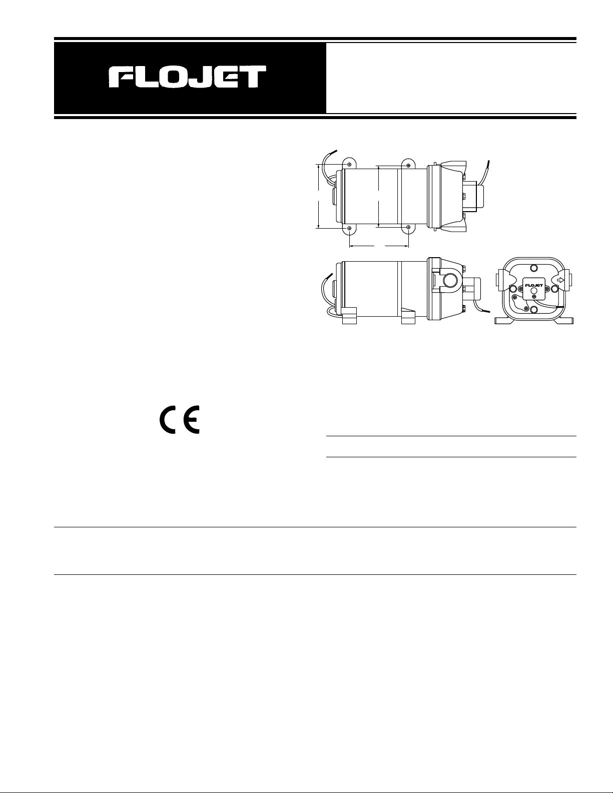
Pump Series Dimensions - Inches (mm) Weight
Height Width Length lb. (kg)
4405-XXX 3.75 (95) 6.3 (160) 8.2 (208) 3.9 (1.8)
AMP DRAW FLOW PRESSURE SWITCH
MODEL* VOLTS @ 10 psi (0.7 bar) GPM (l/min) MAX psi (bar)
4405-143 12V dc 3.9 3.3 (12.5) 35 (2.4)
4405-343 24V dc 2.0 3.3 (12.5) 35 (2.4)
4405-443 32V dc 1.3 3.3 (12.5) 35 (2.4)
* CE fully suppressed models are identified by a prefix “R” and a CE mark on the label. (i.e. R4405-343).
Self Declaration Of Conformance (SDOC) is available upon request.
Model 4405 Series
3.5
(90)
3.44
(87)
3.25
(82)
Page 2
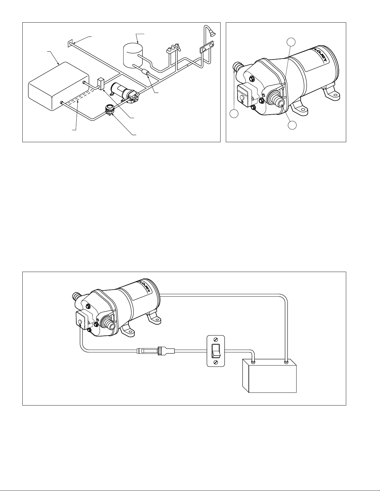
STEP I
Remove shipping plugs from Quad pump ports. Some
water from factory testing may spill out.
STEP 2
Install inlet A and discharge B port connectors. Firmly
push slide clips C forward to lock port connectors in
place.
STEP 3
Slide rubber mounts fully into 4 mounting tracks.
STEP 4
Mount pump vertically, with pump head down or
horizontally in an accessible location. If mounting
vertically, motor up, attach motor mounts first then
pump head mounts, while supporting weight of pump.
STEP 5
Use 1/2” I.D. flexible hose (preferably braided or
reinforced). Use hose clamps on the slip-on barb hose
connectors.
STEP 6
Install a 3/8” I.D. hose for feed lines. Use high pressure
hose on all city water lines.
STEP 7
Install a Flojet strainer in an accessible location (for
inspection and cleaning) between the tank and pump
inlet. This strainer or equivalent is required for pump
warranty to be valid.
NOTE: Do not use with an accumulator tank.
INSTALLATION
STEP I
Use 14 gauge stranded wire to 20’, 12 gauge to 50’,
from power source.
STEP 2
Use a 10-15 amp rated on-off switch on the (+) positive
(red) motor lead.
STEP 3
Install 10-15 amp fuse protection on the positive lead for
the -143 model, use a 7 amp fuse for the -343 and a 5
amp fuse for -443 model.
WIRING
Red (+)
Fuse
(+)
Switch
Battery
(–)
Black (–)
City Water
Inlet
Water
T ank
Autofill Tank V alve ,
Plumb to Tank
Check
Valve
Flojet Inlet
Strainer
Do Not Plumb Autofill
to Pump Suction Line
Water
Heater
B
A
C
Page 3
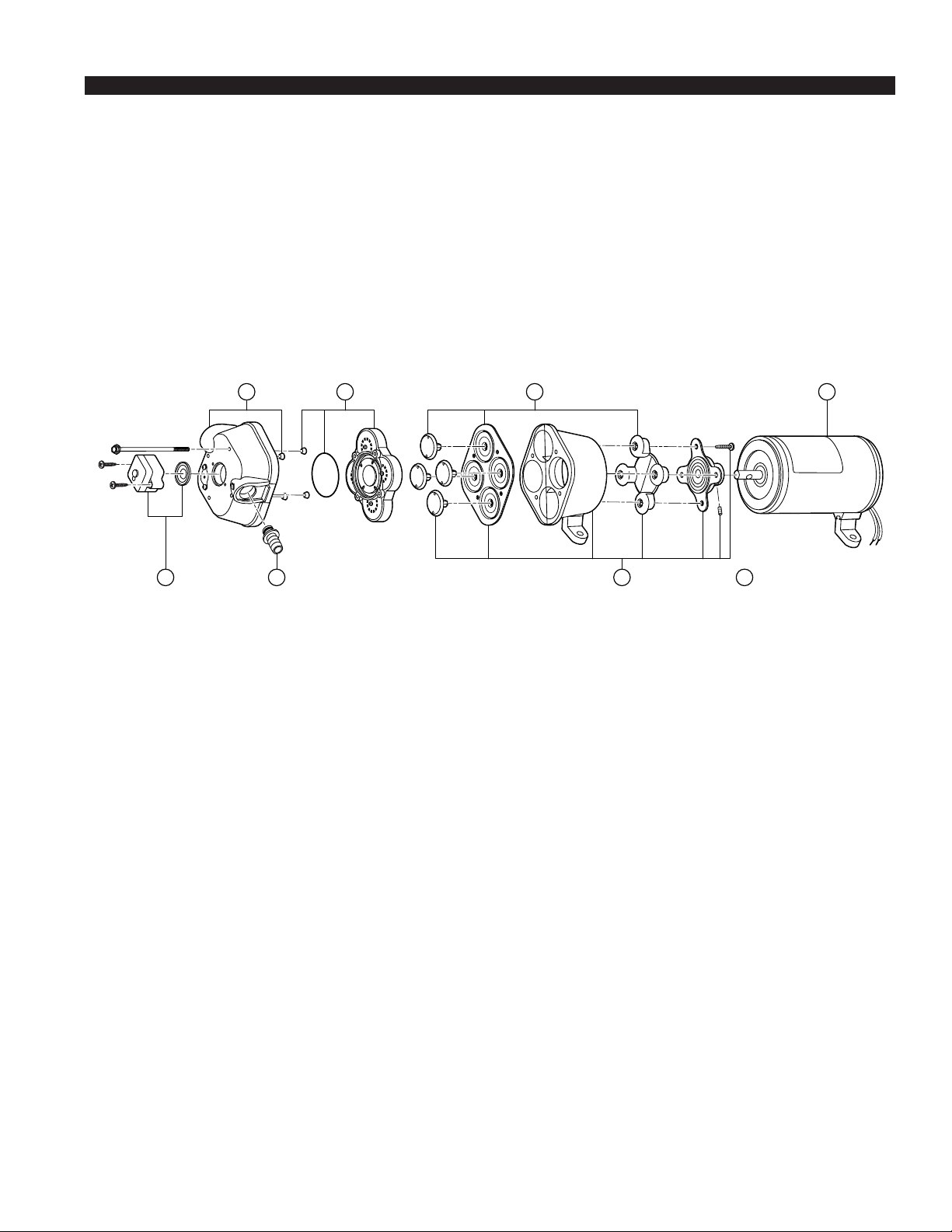
DISASSEMBLE
Upper Housing
1. Remove switch (9). Disconnect switch wires.
Upper Housing
2. Loosen but do not remove four pump head screws and
carefully remove upper housing assembly (1)
3. Inspect check valve (2) for debris
4. Reassemble new upper housing (1)
Check Valve Assembly
Follow steps 2 and 3
3. Replace check valve (2)
4. Reassemble upper housing (1)
Lower Housing, Diaphragm, Motor
Follow step 2, then slide rubber foot from mounting track.
3. Rotate lower housing (4) so mounting notch opening on lower
housing exposes set screw which holds bearing housing to
shaft.
4. Loosen this set screw by inserting wrench 1/8” Allen wrench
into mounting notch opening. Then, slide lower housing (4) off
motor shaft.
Diaphragm Cont’d
5. Loosen four cam piston screws with Phillips head screw
driver and pull apart cam from inner pistons. (Pistons should
always be replaced when a new diaphragm is installed.)
Motor Cont’d
5. Replace Motor
REASSEMBLE
Motor
1. Reassemble lower housing assembly (4) to motor. (Follow
steps 4 to 10.)
Diaphragm
2. Lower housing is assembled with:
• Flat side of diaphragm and outer pistons facing motor
• Hex stem of inner pistons must be aligned into hex holes in
outer pistons (4).
• Outer pistons must be aligned with alignment slots on cam
assembly making sure screw holes align in cam assembly,
otherwise diaphragm will leak.
3. Tighten cam piston screws partially, center piston in
diaphragm, then tighten screws securely (18 in. lbs. torque)
Lower Housing
4. Reassemble lower housing assembly (4) to motor.
5. Retighten set screw securely. Set screw head must be
positioned facing motor covering seam (indentation).
(Positioning of this screw is critical to avoid misalignment and
subsequent diaphragm damage.)
Upper Housing, Check Valve
6. Reassemble upper housing (1) and slide clips (8)
7. Properly seat O-Ring in check valve assembly (2) and check
if ferrules and screen are in place on upper housing (1)
8. Install check valve (2) into upper housing (1) and push in.
9. Assemble on to lower housing (4), align 4 screws on to motor
by rotating lower housing (4) if necessary to align feet.
10. Tighten screws evenly to 30 in. lbs. torque.
Pressure Switch
1. Place switch against front of pump (9), insert screws and take
care not to cross thread or strip out threads in housing.
2. Reconnect wires.
TROUBLESHOOTING
WARNING: BEFORE SERVICING PUMP, TURN OFF PUMP AND DRAIN WATER FROM SYSTEM!!
Failure to Prime - Motor operates, but no pump discharge
• Restricted intake or discharge line
• Air leak in intake line
• Debris in pump
• Punctured pump diaphragm (pump leaks)
• Crack in pump housing
Motor falls to turn on
• Loose wiring connection
• Pump circuit has no power
• Blown fuse
• Pressure switch failure
• Defective motor
Pulsating Flow
• Restricted pump delivery. Check discharge lines, fittings and
valves for clogging or undersizing
Pump Fails to Turn Off After All Fixtures Are Closed
• Empty water tank
• Insufficient voltage to pump (low battery)
• Punctured pump diaphragm (pump leaks)
• Discharge line leak
• Defective pressure switch
Low Flow and Pressure
• Air leak at pump intake
• Accumulation of debris inside pump and plumbing
• Worn pump bearing (excessive noise)
• Punctured pump diaphragm (pump leaks)
• Defective motor
21
4 7 Includes items 1 thru 49 6
3 5
Quite often when a pump is worn or defective the one failed component has overburdened others. To avoid frequent aggravating
repairs, Flojet offers service kit assemblies making repairs as quick and easy as possible.
Page 4
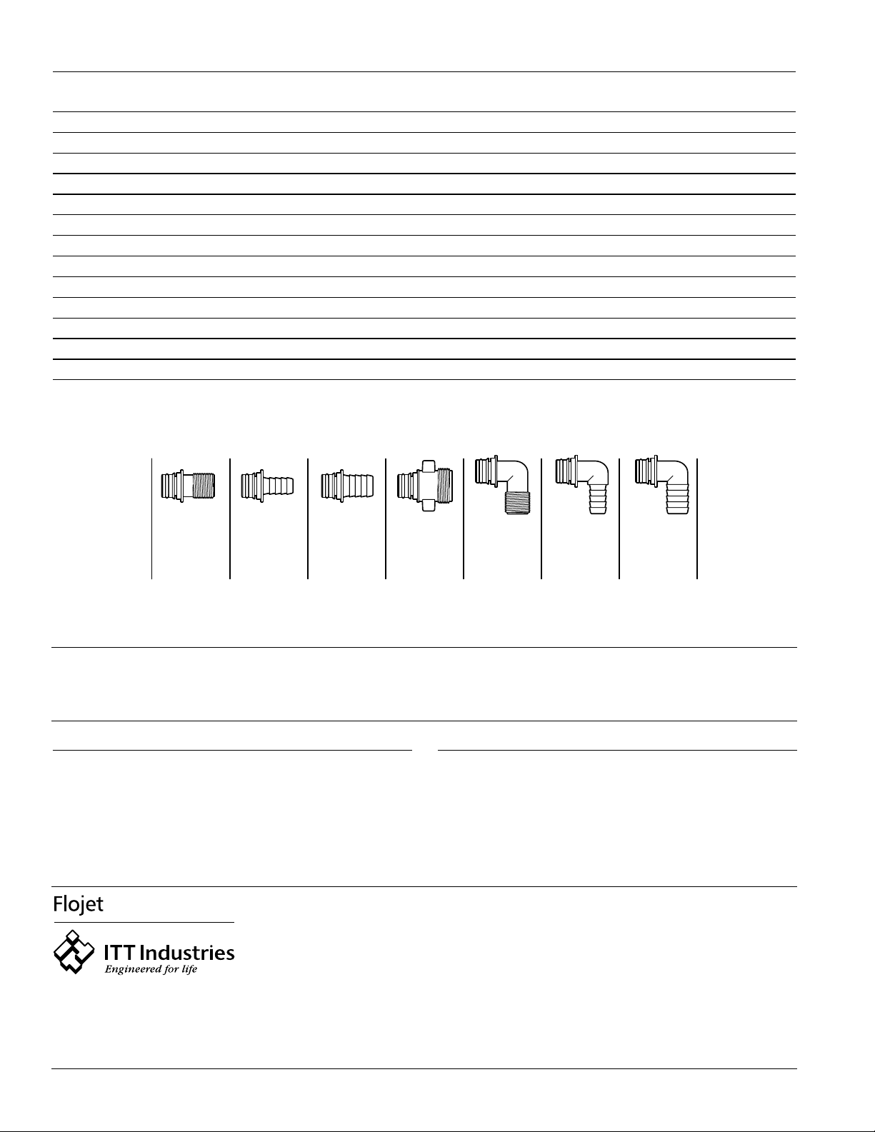
Pump Series Strainer Number Inlet Outlet Screen
4405-XXX 1740-012 1/2 Barb Quad Port 40 Mesh
1740-002 1/2 Barb 1/2 Barb 40 Mesh
1740-004 1/2 M Qest 1/2 M Qest 40 Mesh
1740-014 1/2 M Qest Quad Port 40 Mesh
STRAINERS
ACCESSORIES
20381-000
QUAD PORT x
1/2" MALE QEST.
STRAIGHT
20381-002
QUAD PORT x
1/2" HOSE BARB
STRAIGHT
20381-006
QUAD PORT x
3/4" HOSE BARB
STRAIGHT
20381-007
QUAD PORT x
GARDEN HOSE
ADAPTOR
20381-008
QUAD PORT x
1/2" MALE QEST.
90° ELBOW
20381-009
QUAD PORT x
1/2" HOSE BARB
90° ELBOW
20381-010
QUAD PORT x
3/4" HOSE BARB
90° ELBOW
QUICK CONNECT PORT SYSTEM
UNITED KINGDOM
Jabsco/Flojet
Bingley Road, Hoddesdon
Hertfordshire EN11 OBU
Tel: +44 (0) 1992 450145
Fax: +44 (0) 1992 467132
CANADA
Fluid Products Canada
55 Royal Road
Guelph, Ontario N1H 1T1
Tel: (519) 821-1900
Fax: (519) 821-2569
JAPAN
NHK Jabsco Company Ltd.
3-21-10, Shin-Yokohama
Kohoku-Ku, Yokohama, 222
Tel: 045-475-8906
Fax: 045-475-8908
U.S.A.
Flojet
20 Icon
Foothill Ranch, CA 92610-3000
Tel: (949) 859-4945
Fax: (949) 859-1153
GERMANY
Jabsco GmbH
Oststrasse 28
22844 Norderstedt
Tel: +49-40-53 53 73-0
Fax: +49-40-53 53 73-11
© Copyright 2001, ITT Industries Printed in U.S.A. All Rights Reserved Form: 81000-224 11/01
AUTOMATIC WATER SYSTEM PUMP SERVICE PARTS
WARRANTY
FLOJET warrants this product to be free of defects in material
and/or workmanship for a period of two years after purchase by
the customer from FLOJET. During this two year warranty period,
FLOJET will at its option, at no charge to the customer, repair or
replace this product if found defective in material or workmanship,
with a new or reconditioned product, but not to include costs of
removal or installation.
This is only an overview of our limited warranty. If you would like a
copy of our warranty, please call or write FLOJET.
RETURN PROCEDURE
Prior to returning any product to FLOJET, call customer service for
an authorization number. This number must be written on the
outside of the shipping package. Place a note inside the package with an explanation regarding the reason for return as well
as the authorization number. Include your name, address and
phone number.
MODEL#
KEY# DESCRIPTION 4405-143 4405-343 4405-443
0 Service Kit* 20409-043 20409-043 20409-043
1 Upper Housing With Clips 20404-002 20404-002 20404-002
2 Check Valve Assembly 20407-030 20407-030 20407-030
3 Diaphragm Assembly (includes screws) 20403-040 20403-040 20403-040
4 Lower Housing Assembly 20419-001 20419-001 20419-001
5 Motors 2009-073A 2019-023A 2049-025A
Motors CE Models R2009-073A R2019-023A —
6 Ports - 1/2 Barb (pair) 20381-002 20381-002 20381-002
Ports - 1/2 Qest (pair) .20381-000 20381-000 20381-000
Ports - 3/4 Barb (pair) 20381-006 20381-006 20381-006
7 Pump Head Assembly 20406-003A 20406-003A 20406-003A
8 Side Clips (pair) 20408-000 20408-000 20408-000
9 Pressure Switch Assembly 02090-104 02090-104 02090-104
*Service Kit includes #2, #3, #8 and drive cam assembly.
The above part numbers are packaged with 2 fittings per bag.
 Loading...