

Flo Fab 2FFSTEP Installation, Operation & Maintenance Manual
Submersible Euent Pumps
2FFSTEP
0.5 & 1 HP @ 3450 RPM
Installation, Operation &
Maintenance Manual
IMPORTANT! - Read all instructions in this manual before operating or servicing
a pump.
General Safety Information
Before installation, read the following
instructions carefully. Failure to
follow instruction and safety
information could cause serious
bodily injury, death and/or property
damage. Each Flo Fab product is
carefully inspected to insure proper
performance. Closely following these
instructions will eliminate potential
operating problems, assuring years
of trouble-free service.
DANGER
"Danger" indicates an
imminently hazardous situation
which, if not avoided, WILL result in
death or serious injury.
WARNING
"Warning" indicates
an imminenty hazardous situation
which, if not avoided, MAY result in
death or serious injury.
CAUTION
"Caution" indicates a
potentially hazardous situation
which, if not avoided, MAY result in
minor or moderate injury.
IMPORTANT! - Flo Fab Pumps is not
responsible for losses, injur y or
death r e sulting from failure to
observe these safety precautions,
misuse, abuse or misapplication of
pumps or equipment.
ALL R E TURNED
P R ODUC T S MUST B E
CLEANED, SANITIZED, OR
DECONTAMINATED PRIOR TO
SHIPMENT, TO INSURE EMPLOYEES
WILL NOT BE EXPOSED TO HEALTH
HA Z ARDS IN HANDLING SAID
MATERIAL. ALL APPLICABLE LAWS
AND REGULATIONS SHALL APPLY.
WARNING
junc tion connec tions must be in
accordance with the National Electric
Code and all applicable state and local
codes. Requirements may vary depending
on usage and location.
Installation, wiring, and
WARNING
I nstalla tion and
servicing is to be conducted by
qualied personnel only.
Keep clear of suction and
discharge openings. Do not
insert ngers in pump with
power connected; the impeller can
cause serious injury.
Always wear eye protection
when working on pumps. Do
not wear loose clothing that
may become entangled in moving
parts.
DANGER
Pumps build up heat
and pressure during
operation. Allow time
for pumps t o c ool
before handling or servicing the
pump or a ny accessor y i tems
associated with or near the pump.
DANGER
T his pump is not
i n t ended f or use in
swimming pools or water
installations where there is
human contact with pumped uid.
DANGER
Risk of electric shock. To
reduce risk of electric shock,
always disconnec t pump
from power source before
handling any aspect of the pumping
system. Lock out power and tag.
WARNING
Do not use these
pumps in water over 104º F. Do not
exceed manufacturers recommended
maximum performance, as this could
cause the motor to overheat.
DANGER
Do not lift, carry or
hang pump by the electrical
cables. Damage to the
electrical cables can cause
shock, burns or death. Never handle
connected power cords with wet
hands. Use appropriate lifting device.
WARNING
Sump and sew age
pumps often handle materials which
could cause illness or disease. Wear
adequate protective clothing when
working on a used pump or piping.
Never enter a basin after it has been
used.
DANGER
Failure to permanently
ground the pump, motor and
controls before connecting
to power can cause shock,
burns or death.
DANGER
These pumps are not to
be installed in locations
classied as hazardous in
accordance with the National
Electric Code, ANSI/NFPA 70.
WARNING
The Uniform Plumbing
Code ( UPC ) sta tes that sewage
systems shall have an audio and visual
alarm that signals a malfunction of the
systems, that are required to reduce
the potencial for property damage.
IMPORTANT! - Prior to installation,
record Model Number, Serial, Amps,
Voltage, Phase and HP from pump
name plate for the future reference.
Also record the Voltage and Current
Readings at Startup:
Model Number: ____________________
Serial: ____________________
Amps:_______ Voltage:_______
Phase:_______ HP:_______
01
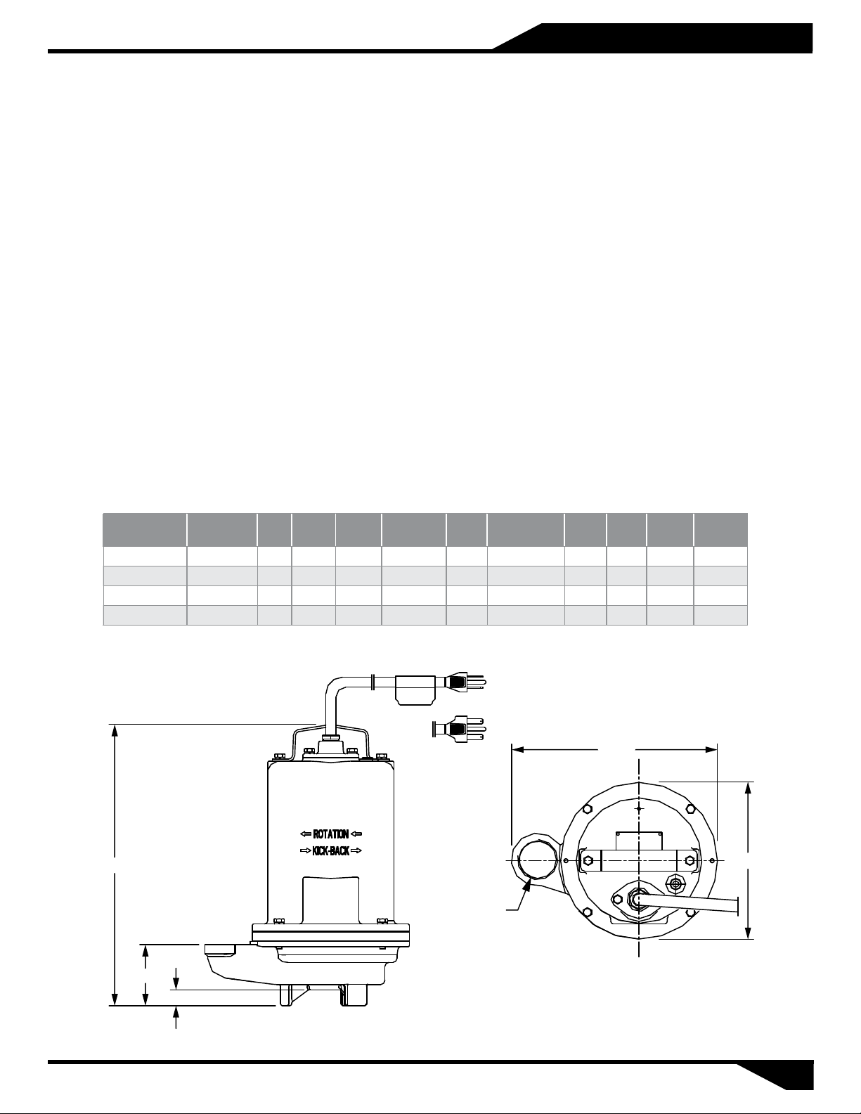
Specications & Dimensions
DISCHARGE: 2" NPT, vertical.
SPHERICAL SLD HNDLG: 3/4"
LIQUID TEMPERATURE: 104° F (40° C) continuous.
VOLUTE: Cast iron ASTM A-48 class 30.
MOTOR HOUSING: Cast iron ASTM A-48 class 30.
SEAL PLATE: Cast iron ASTM A-48 class 30.
IMPELLER: Single vane enclosed. Polypropylene with stainless steel insert.
SHAFT: Stainless steel.
O-RINGS: Square shaped Buna-N.
PAINT: Air dry enamel, water based.
SEAL: Outboard single mechanical, oil lled chamber. carbon / ceramic / Buna-N, with
stainless steel hardware.
HARDWARE: 300 series stainless steel.
CORD ENTRY: 20 ft of neoprene cord, sealed against moisture.
BEARINGS: Ball, single row, oil lubricated.
MOTOR: NEMA L, single phase, permanent split capacitor, oil lled, with
overload
in motor.
OPTIONAL EQUIPMENT: Additional cord, seal material, impeller trims, slide rail coupling (SRC-2).
protection
MODEL PART No. HP VOLTS PHASE
2FFSTEP
2FFSTEP
2FFSTEP
2FFSTEP
A = Automatic Float Switch.
16.53"
512 0.5 115 1 3450 13.1 26.2 G 14/3 SOW 80
512A 0.5 115 1 3450 13.1 26.2 G 14/3 SOW 80
522 0.5 230 1 3450 5.6 13.2 E 14/3 SOW 80
1022
-
-
-
- 1 230 1 3450 9.1 23.5 f 14/3 SOW 80
RPM
(Nominal)
MAX
AMPS
2" NPT
LOCKED
ROTOR AMPS
NEMA
CODE
CORD
SIZE
12.16"
CORD
TYPE
WEIGHT
(pounds)
9.25"
3.6"
0.94"
02
Recommendations and Warnings
Receiving inspection
Upon receiving the pump, it should
be inspected for damage or
shortages. If damage has occurred,
le a claim immediately with the
company that delivered the pump. If
the manual is removed from the
packaging, do not lose or misplace.
Storage
Any product that is stored for a
period longer than six (6) months
from the date of purchase should be
bench tested prior to installation. A
bench test consists of, checking the
impeller to assure it is free turning
and a run test to assure the motor
(and switch if provided) operate
properly.
Controls
Manual models require a separate
approved pump control device or
panel for automatic operation. Be
sure the ele
control selected properly match the
electrical specications of the pump.
ctrical specication of the
Installation
There are two methods of installing
euent pumps:
1. In a Flex-Hose system, most
commonly used in interceptor
tanks, and
2. A slide rail in a package system or
concrete wet well, which allows
the pump(s) to be installed or
removed without requiring
personnel to enter the wet well.
The sump, basin or lift station shall
be sealed and vented in accordance
with local plumbing codes. This
pump is designed to pump
sewage, euent or wastewater,
non-explosive and non-corrosive
liquids and shall NOT be installed
in locations classied as hazardous
in accordance with the National
Electrical Code (NEC) ANS
70 or Canadian Electric Code (CEC).
The pump should never be installed
in a trench, ditch, or hole with a dirt
bottom. The legs will sink into the
dirt and the suction will become
plugged.
I/NFPA
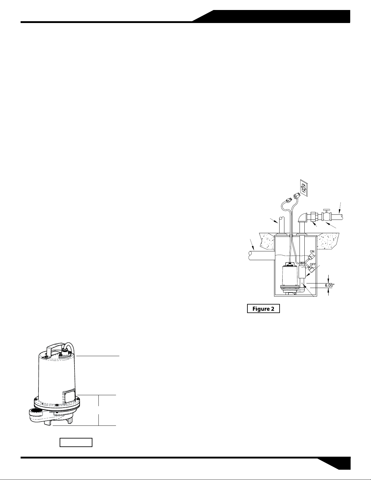
Liquid Level Controls
Typical Discharge Pipe Mounted:
Refer to Figure 2 below which shows
a typical installation of a 1 phase 120
or 240 volt pump using a level
control mounted to the discharge
piping with a piggy-back plug. The
level control should have adequate
clearance so it cannot hang up in it’s
swing and that the pump is
completely submerged when the
level control is in the "O" mode. By
adjusting the cord tether the control
level can be changed.
Typical Installation with Wide
Angle Level Control
DISCHARGE
VENT
UNION
INLET
GATE
VALVE
CHECK VALVE
Submergence
The pump should always be
operated in the submerged
condition. The minimum sump liquid
level should never be less than above
the pump’s volute (See Figure 1).
Recommended
Submergence
Level
Minimum
Submergence
Level
6"
Bottom of Feet
Figure 1
The installation should be at a
sucient depth to ensure that all
plumbing is below the frost line. If
this is not feasible, remove the check
valve and size the basin to
accommodate the additional
backow volume.
Discharge Piping
Discharge piping should be as short
as possible and sized no smaller than
the pump discharge. Do not reduce
the discharge pipe size below that
which is provided on the pump.
Both a check valve and a shut-o
valve are recommended for each
pump. The check valve is used to
prevent backow into the sump. The
shut-o valve is used to manually
stop system low during pump
servicing.
Drill ¼" dia. vent hole
to prevent air locking
Level Control Basic Instructions:
Plug the level control plug into the
GFI receptacle, then plug the pump
into the piggy-back plug (See Figure
3). One cycle of operation should be
observed, so that any potential
problems can be corrected.
It is recommended that the level
control oat should be set to insure
that the liquid in the sump never
drops below the top of the motor
housing or a minimum level of 6
inches above the basin oor.
03
 Loading...