

Page 1

FLOE VSD 5000 PONTOON LIFT
P/N 511-50085-01 LIFT FRAME
WITH PATENTED EASY- LEVEL
TM
LEG SYSTEM
ASSEMBLY INSTRUCTIONS
©Manufactured by:
Floe International Inc.
48473 State Hwy. 65
McGregor, MN 55362
www.floeintl.com
Instruction P/N 611-50085-01 Rev H
Issued 5/7/2018
Page 2

Required Tools
Page 3

Card Contents
(511-04255-00)
Step
Part Numbers
QTY
Descriptions
Torques
001-70215-00
001-70217-00
001-70210-00
001-70219-00
001-71023-00
001-76072-00
6
8
8
2
48
24
HHCS, 1/2-13 x 3” ss 18-8
HHCS, 1/2-13 x 3 1/2” ss 18-8
HHCS, 1/2-13 x 1 3/4” ss 18-8
HHCS, 1/2-13 x 4” ss 18-8
FLAT WASHER, .5 ID x .75 OD ss
NUT, 1/2-13 ALUMINUM NYLOCK
60 ft. lbs.
45 ft. lbs.
45 ft. lbs.
60 ft. lbs.
001-70218-00
001-76072-00
4
4
HHCS, 1/2-13 x 3 3/4” ss 18-8
NUT, 1/2-13 ALUMINUM NYLOCK
20 ft. lbs.
001-76071-00
001-70115-00
001-70117-00
8
4
4
NUT, 3/8-16 ALUMINUM NYLOCK
HHCS, 3/8-16 x 3” ss 18-8
HHCS, 3/8-16 x 3 1/2” ss 18-8
35 ft. lbs.
001-70124-00
001-70127-00
001-76071-00
001-70121-00
2
1
6
3
HHCS, 3/8-16 x 5 1/2” ss 18-8
HHCS, 3/8-16 x 7” ss 18-8
NUT, 3/8-16 ALUMINUM NYLOCK
HHCS, 3/8-16 x 4 1/2” ss 18-8
35 ft. lbs.
35 ft. lbs.
35 ft. lbs.
001-70209-00
001-70245-00
001-76350-00
8
1
8
HHCS, 1/2-13 x 1 1/2” ss 18-8
HHCS, 1/2-20 x 1 3/4” ss 18-8
NUT, 1/2-13 ALUMINUM
45 ft. lbs.
50 ft. lbs.
Hardware Card Contents
Page 4
continued
Step
Part Numbers
QTY
Descriptions
Torques
001-70211-00
001-76072-00
001-70227-00
002-04140-00
007-06201-00
4
5
1
1
1
HHCS, 1/2-13 x 2” ss 18-8
NUT, 1/2-13 ALUMINUM NYLOCK
HHCS, 1/2-13 x 7” ss 18-8
CABLE HOLDER
3” CLAMP SHEAVE
45 ft. lbs.
45 ft. lbs.
001-70109-00
001-71017-00
001-76071-00
001-70124-00
001-76071-00
4
8
4
4
4
HHCS, 3/8-16 x 1 1/2” ss 18-8
3/8” SAE FLAT WASHER
NUT, 3/8-16 ALUMINUM NYLOCK
HHCS, 3/8-16 x 5 1/2” ss 18-8
NUT, 3/8-16 ALUMINUM NYLOCK
10 ft. lbs.
35 ft. lbs.
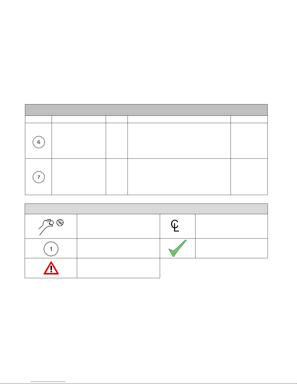
Assembly Image Definitions
Tighten without Clamping
Centerline
Hardware Card #
Check, Inspect, Verify
Important Notice
Page 5
IMPORTANT NOTE:
DO NOT USE IMPACT WRENCH
WHEN ADJUSTING THE EASY
LEVEL LEGS
Warnings
Tips
• Torque nuts to specification, not bolts.
• Place parts and fasteners in designated locations prior to each step.
• Before tightening fasteners to specified torque, ensure that the lift is square.
• Measure from corner to corner (A to C/B to D) to verify that the lift is square.
• Measure distance between corner posts (A to B, B to C, C to D, A to D) above frame beam and at the
top of the corner post to verify that the lift is square.
• Ensure that the lift is level and square before proceeding to install the V-Brace or Ball Screw Tube.
• Assemble cradle clamps with given bolt and nut before installing onto cradle beam.
• Use a marker to denote fasteners which have been tightened to the specified torque.
•
Read instructions and understand them before attempting assembly.
Page 6
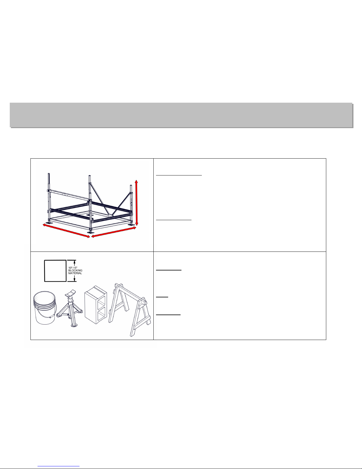
Lift Dimensions
Length: 162”
Width: 135”
Height: 120”
Work Space
Level work space
Allow space to organize parts
Material
Blocking may be anything 10”-15” in height.
(5 gallon bucket, jack stands, blocks, saw horses)
QTY
4 (2 for each side)
Purpose
Blocking used to support lift during assembly steps
1 and 2
Pre-Assembly Prep
Page 7
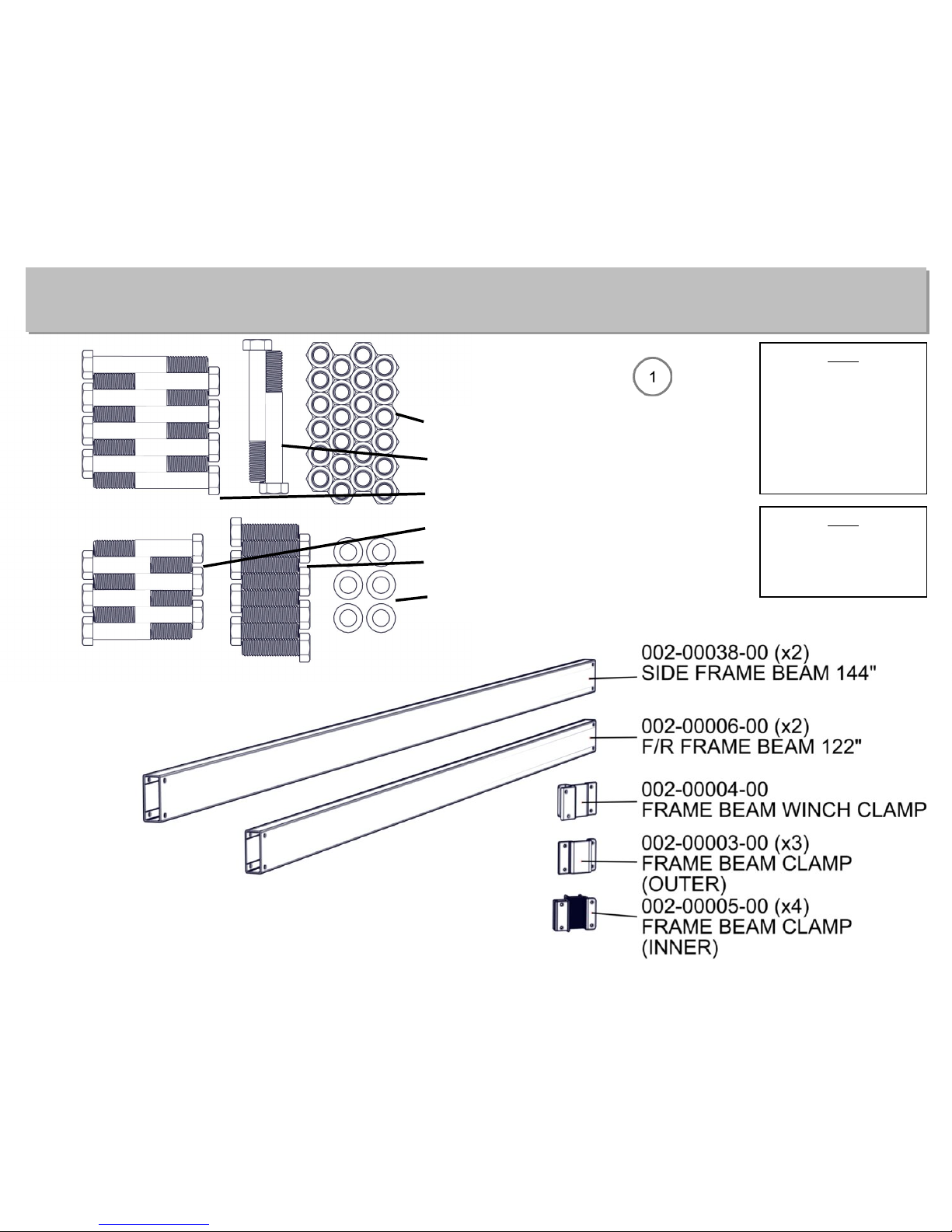
Contents for Step 1
(24) 1/2” Alum. Nylock Nuts
(2) 1/2 x 4” ss Bolts.
(8) 1/2 x 3 1/2” ss Bolts
(6) 1/2 x 3” ss Bolts
(8) 1/2 x 1 3/4” ss Bolts
(48) 1/2” ID x 7/8” OD ss Washers
NOTE
(2) ½” Nylock Nuts
and (2) ½” Washers
are used in Step 6-D
to attach lifting
cables to (2) ½” x 4”
Bolts.
NOTE
ALL FASTENERS IN
STEP 1 ARE HAND-
TIGHTENED ONLY.
Page 8
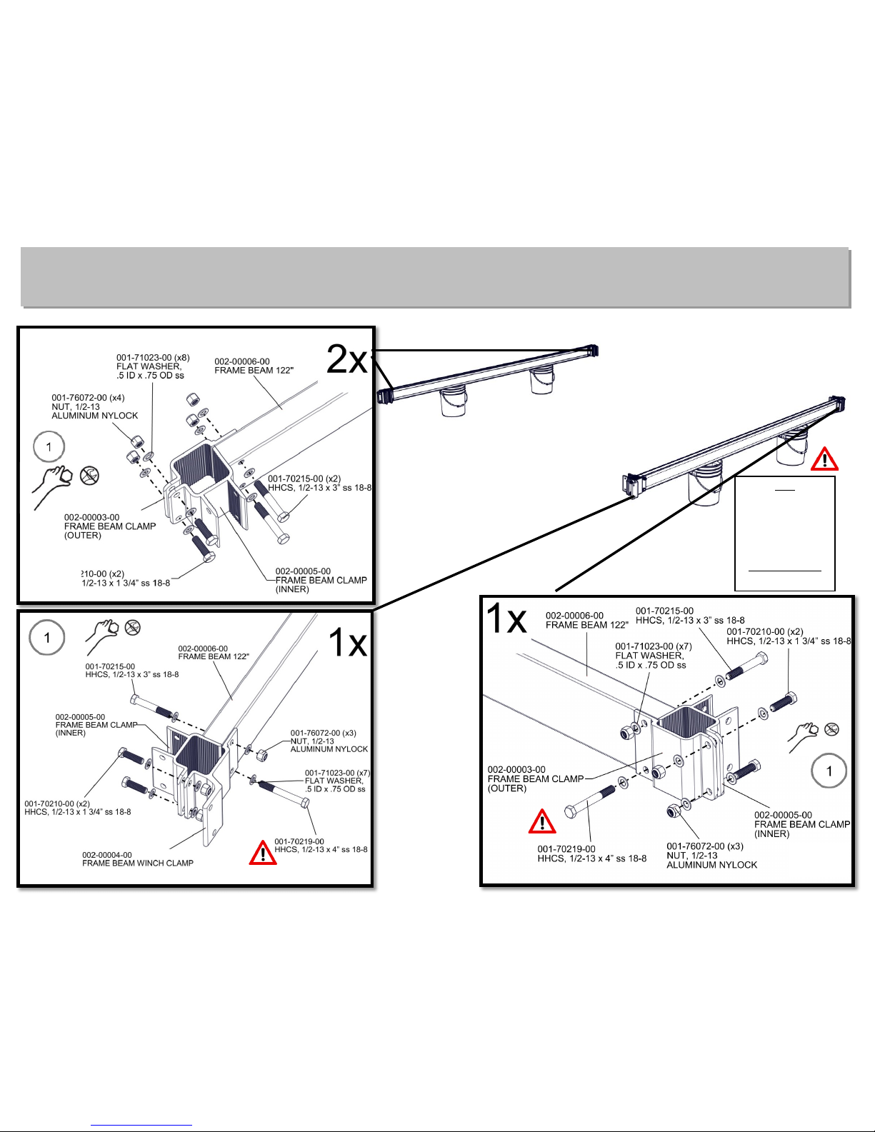
Assembly for Step 1
1-A
1-B
1-C
B
A
D
C
NOTE
(2) ½” Nylock
Nuts and (2) ½”
Washers ARE
NOT used for (2)
½” x 4” Bolts on
corners A and D
until Step 6-D.
Page 9
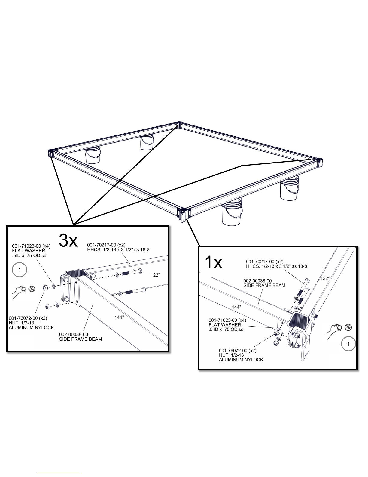
1-E
1-D
B A D
C
Page 10
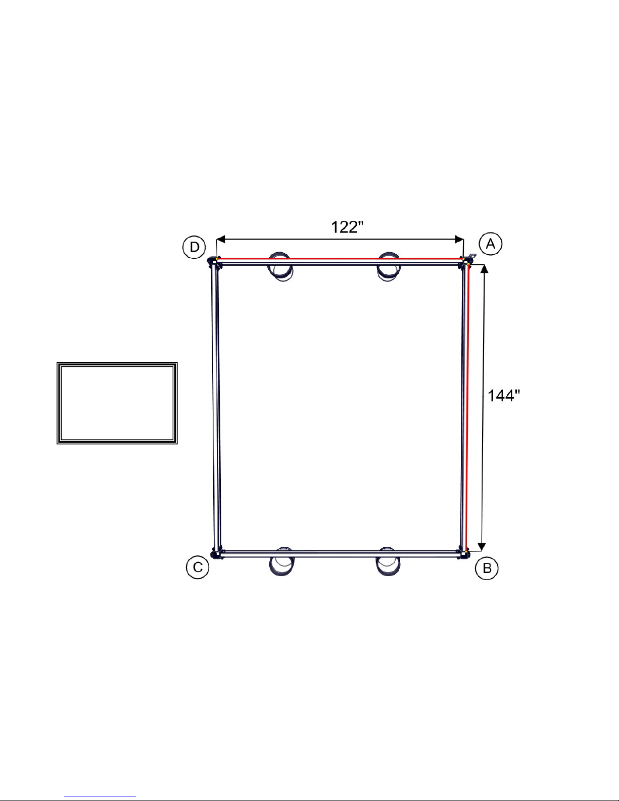
IMPORTANT NOTE:
FRAME BEAMS MUST
BE IN THIS
ORIENTATION
BEFORE CONTINUING.
FRONT/REAR
FRONT/REAR
Page 11

(4) 1/2” Alum. Nylock Nuts
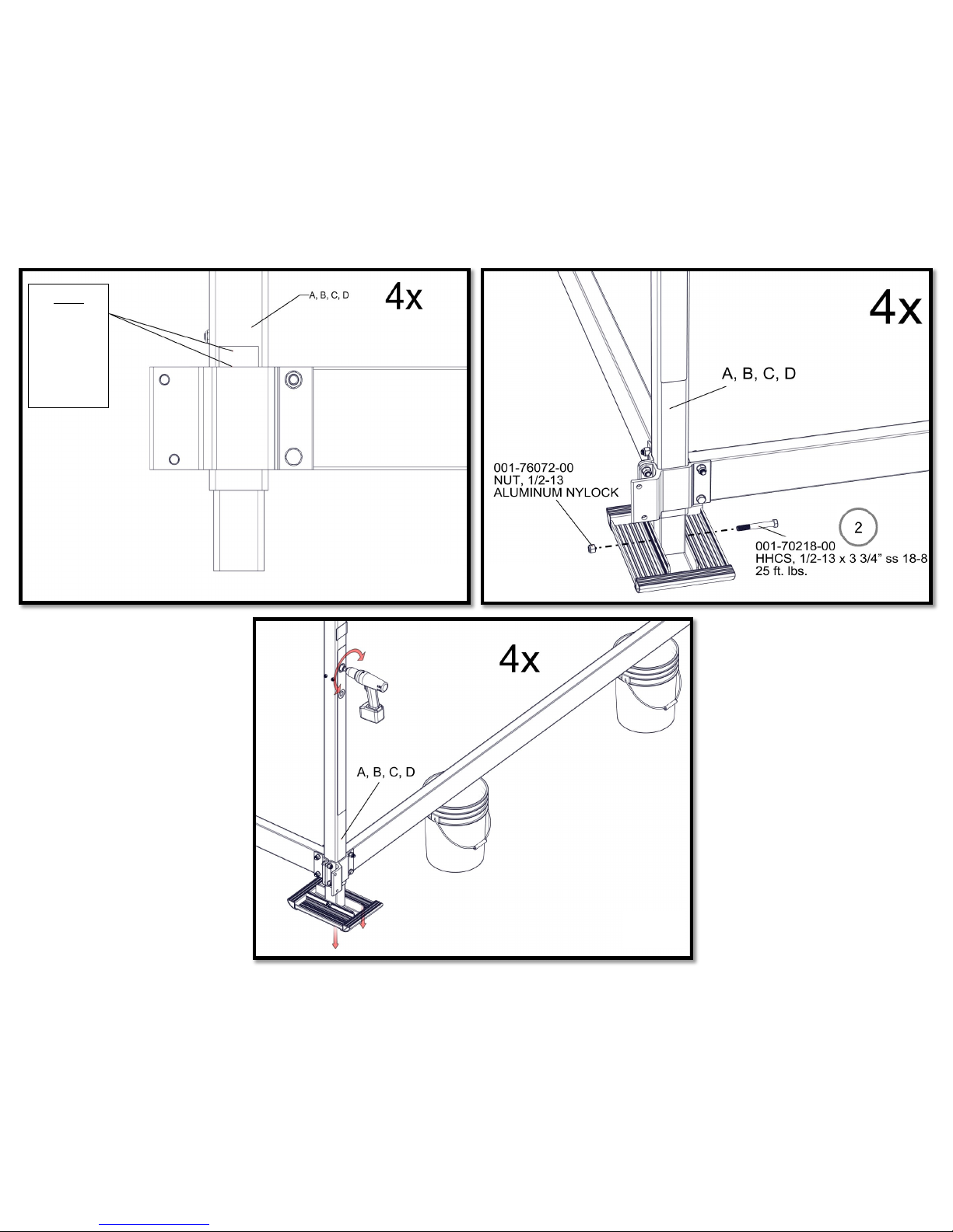
(4) 1/2 x 3 3/4” ss Bolts Torque to 25 ft. lbs.
Contents for Step 2
Page 12
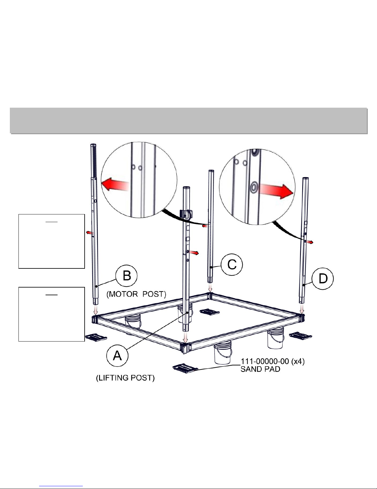
Assembly of Step 2
NOTE
CARRIDGE BOLT
HEADS MUST FACE
INSIDE OF LIFT.
NUTS MUST FACE
OUTSIDE OF LIFT.
NOTE
WATER DEPTH
STICKERS MUST FACE
OUT ON FRONT AND
REAR OF LIFT.
Page 13
NOTE
BUTT
CORNER
POST TAB
UP TO
FRAME
CLAMP
2-A
2-C
2-B
Page 14
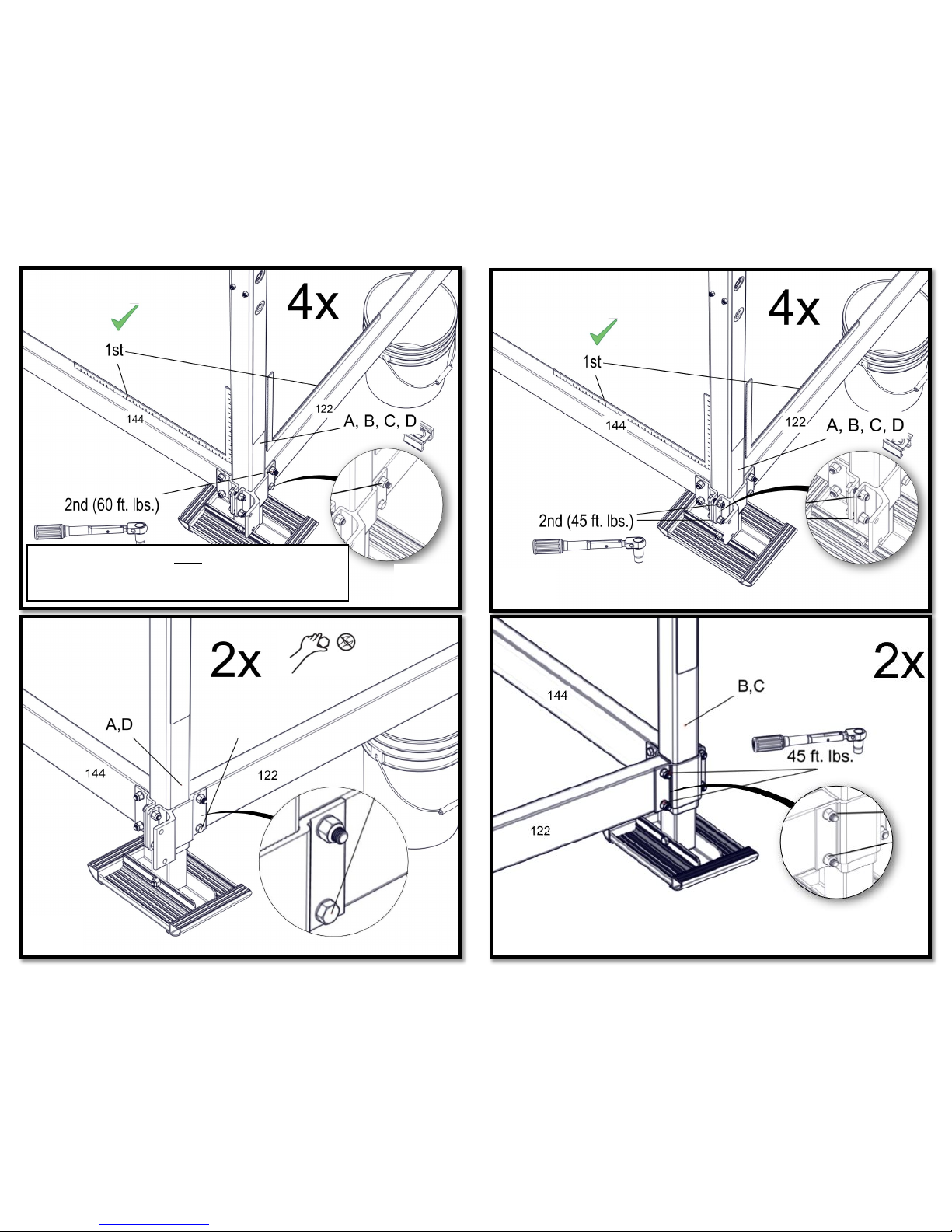
2-D
2-E
2-F
2-G
NOTE
THIS TORQUE SPECIFICATION APPLIES TO THE 3” BOLT
(ABOVE 4” BOLT) BOLTS ON POST A AND POST D ONLY.
Page 15
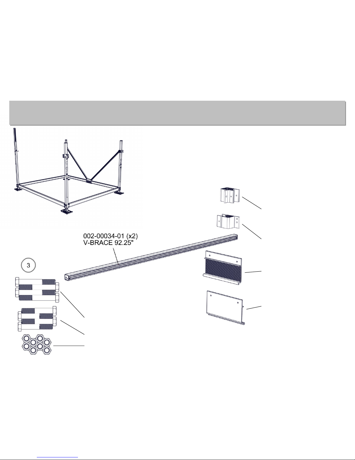
Contents for Step 3
002-00002-00
BRACKET, UPPER V-BRACE – 4”
002-00001-00
BRACKET, UPPER LFTG/V-BRACE
002-04064-00 (X2)
V-BRACE CLAMP
(FEMALE)
002-04066-00 (x2)
V-BRACE CLAMP
(MALE)
(4) 3/8 x 3 1/2” ss Bolts Torque to 35 ft. lbs.
(4) 3/8 x 3” ss Bolts Torque to 35 ft. lbs.
(8) 3/8” Alum. Nylock Nuts
Page 16
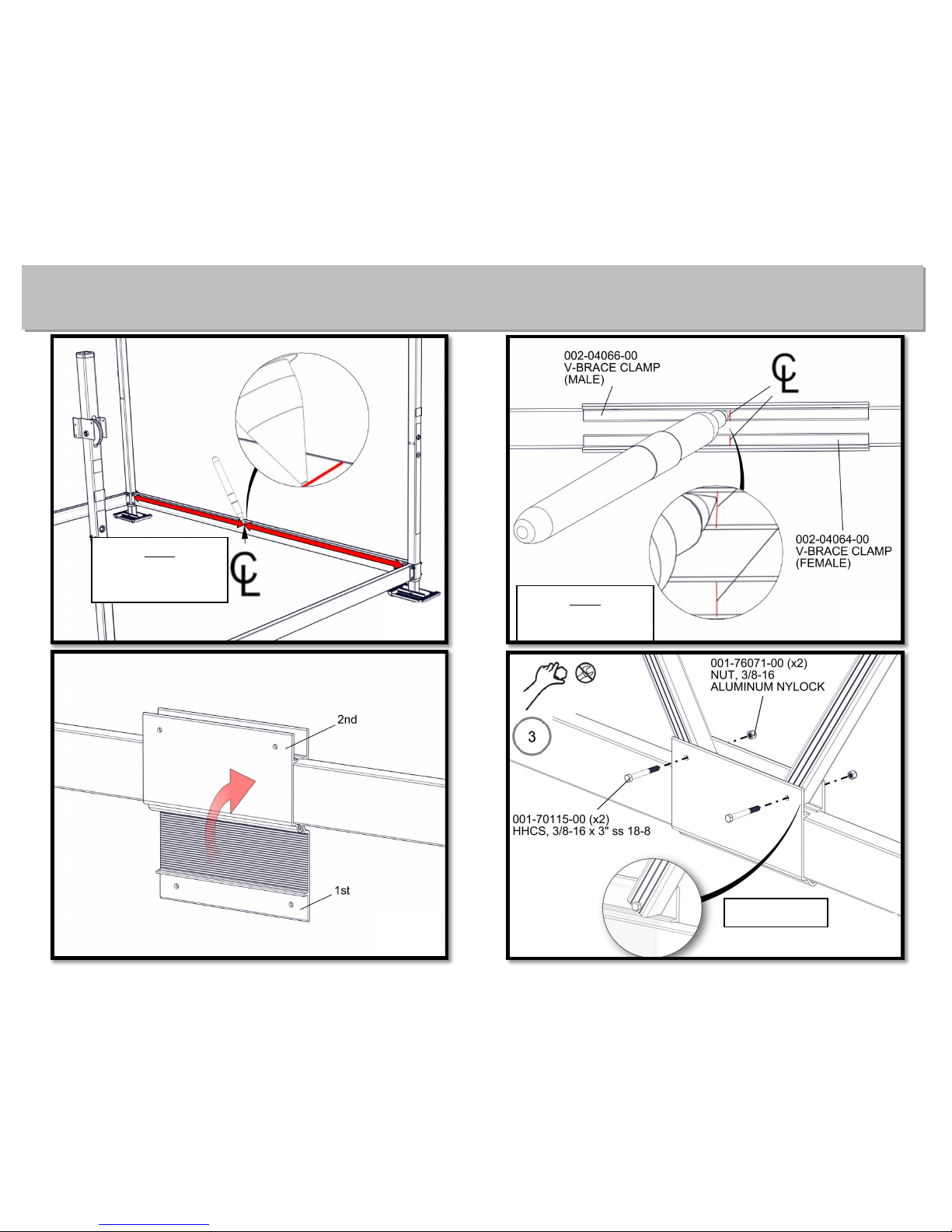
Assembly of Step 3
3-A
3-D
3-B
3-C
NOTE
MARK CENTERLINE
AS SHOWN
NOTE
MARK CENTERLINE
AS SHOWN
INSIDE OF LIFT
Page 17
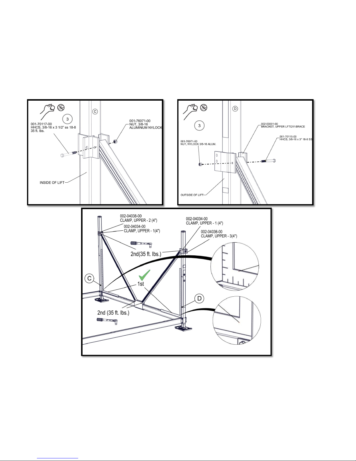
3-E
3-G
3-F
Page 18
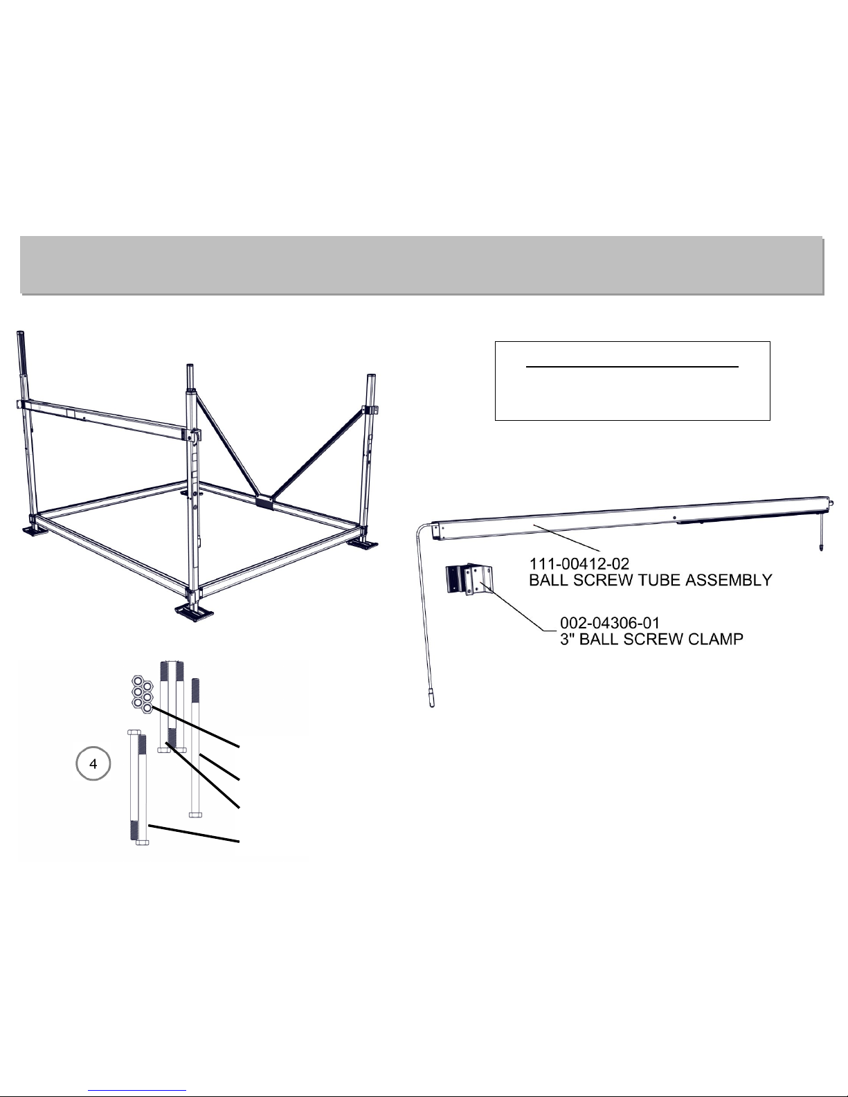
Contents for Step 4
(6) 3/8” Alum. Nylock Nuts
(1) 3/8 x 7” ss Bolts Torque to 35 ft. lbs.
(3) 3/8 x 4 1/2” ss Bolts Torque to 35 ft. lbs.
(2) 3/8 x 5 1/2” ss Bolts Torque to 35 ft. lbs.
ASSEMBLY CAUTION NOTE
Two people are required for
assembly step 4
Page 19
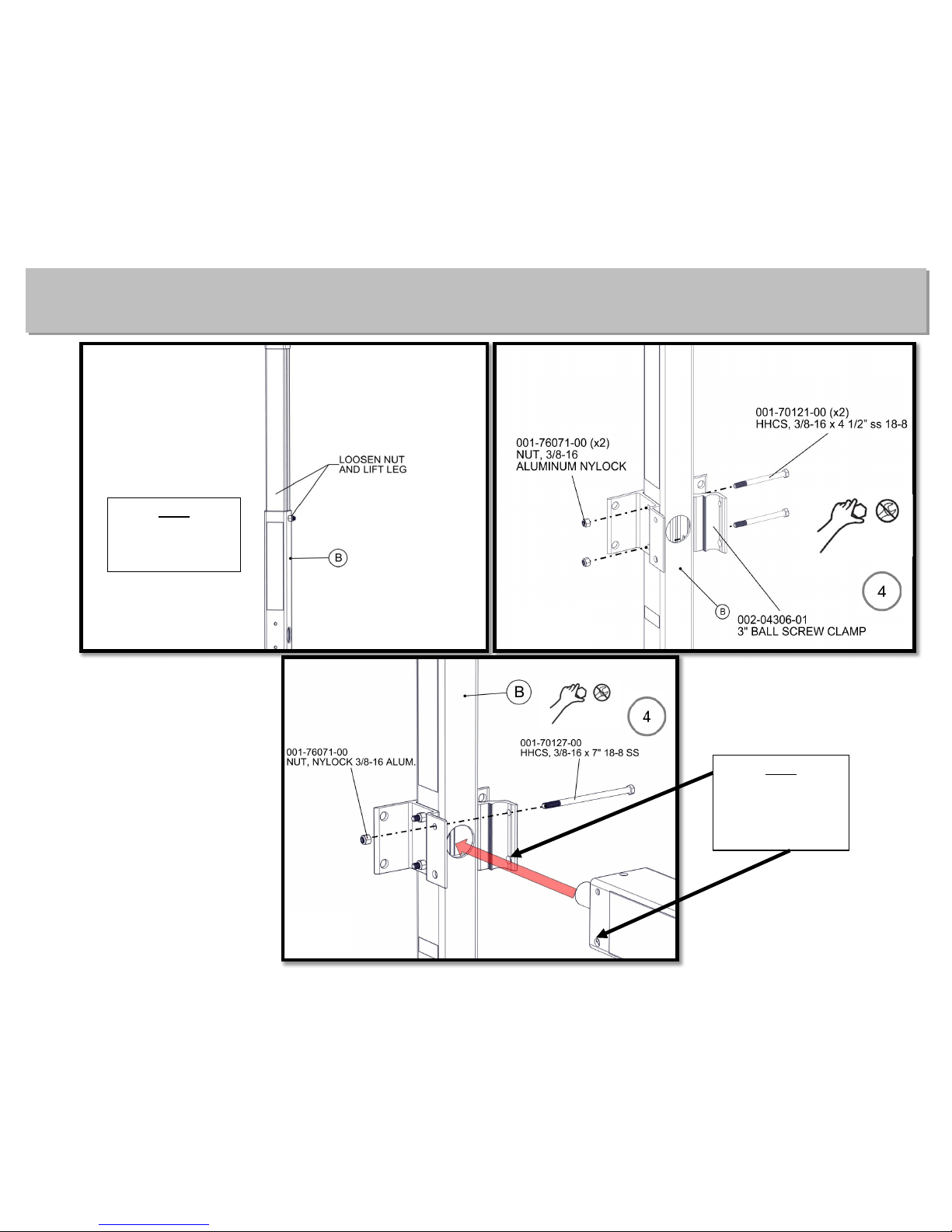
NOTE
DO NOT ALLOW LEG
TO FALL INSIDE
CORNER POST.
Assembly of Step 4
4-C
4-B
4-A
NOTE
MAKE SURE HOLES IN
BALL SCREW ARE
ALIGNED WITH
HOLES IN CLAMP.
Page 20
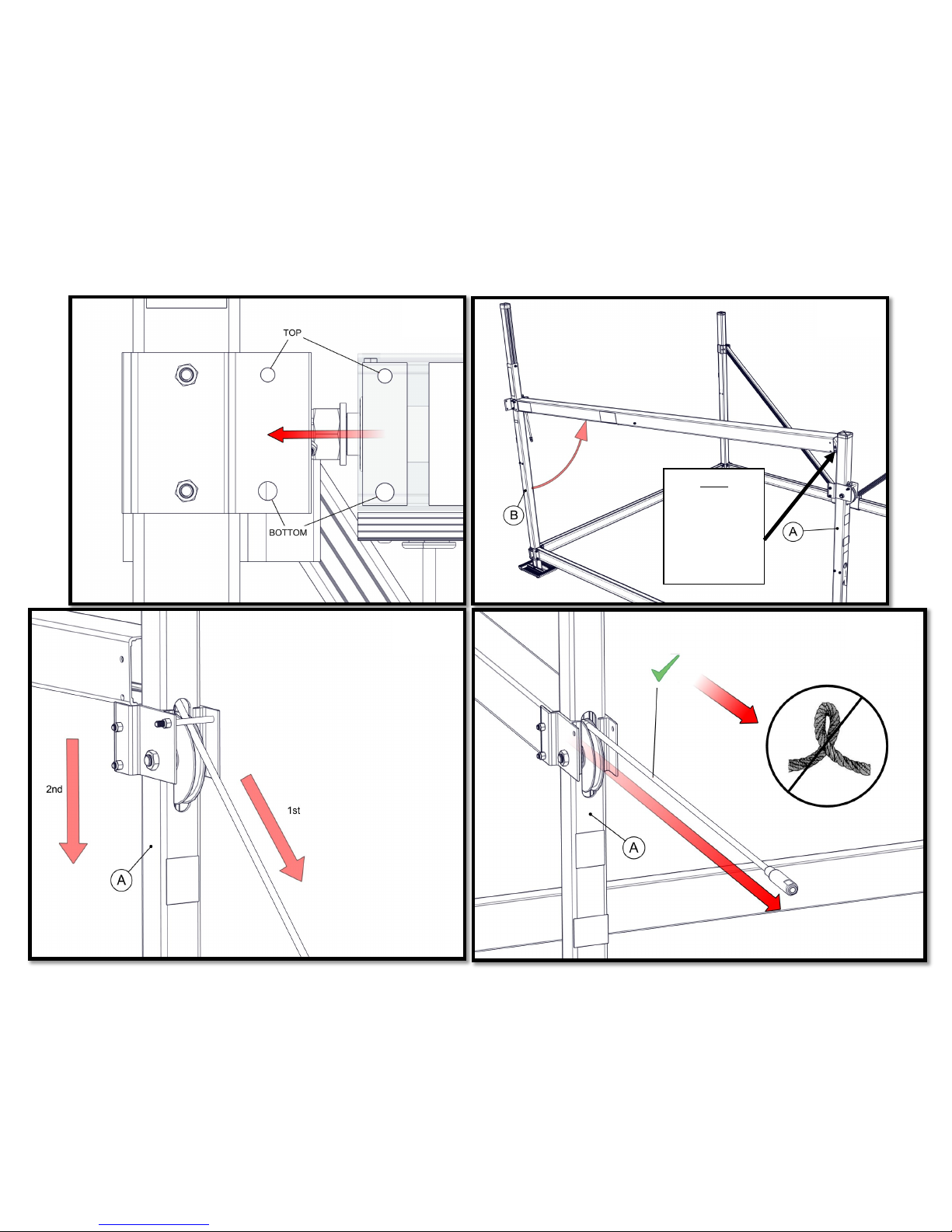
4-D
4-E
4-F
4-G
NOTE
PULL CABLE OUT
OF BALL SCREW
TUBE PRIOR TO
PLACING
BETWEEN
CORNER POSTS.
Page 21
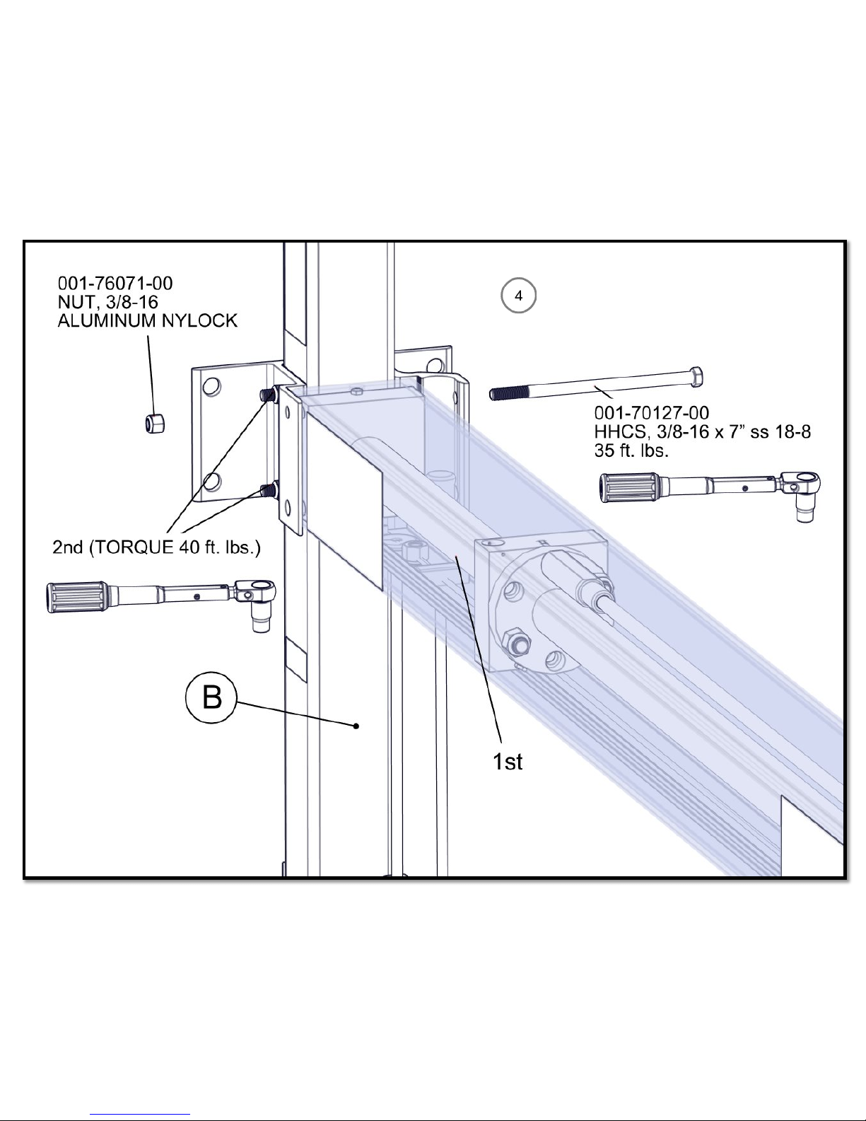
4-H
Page 22
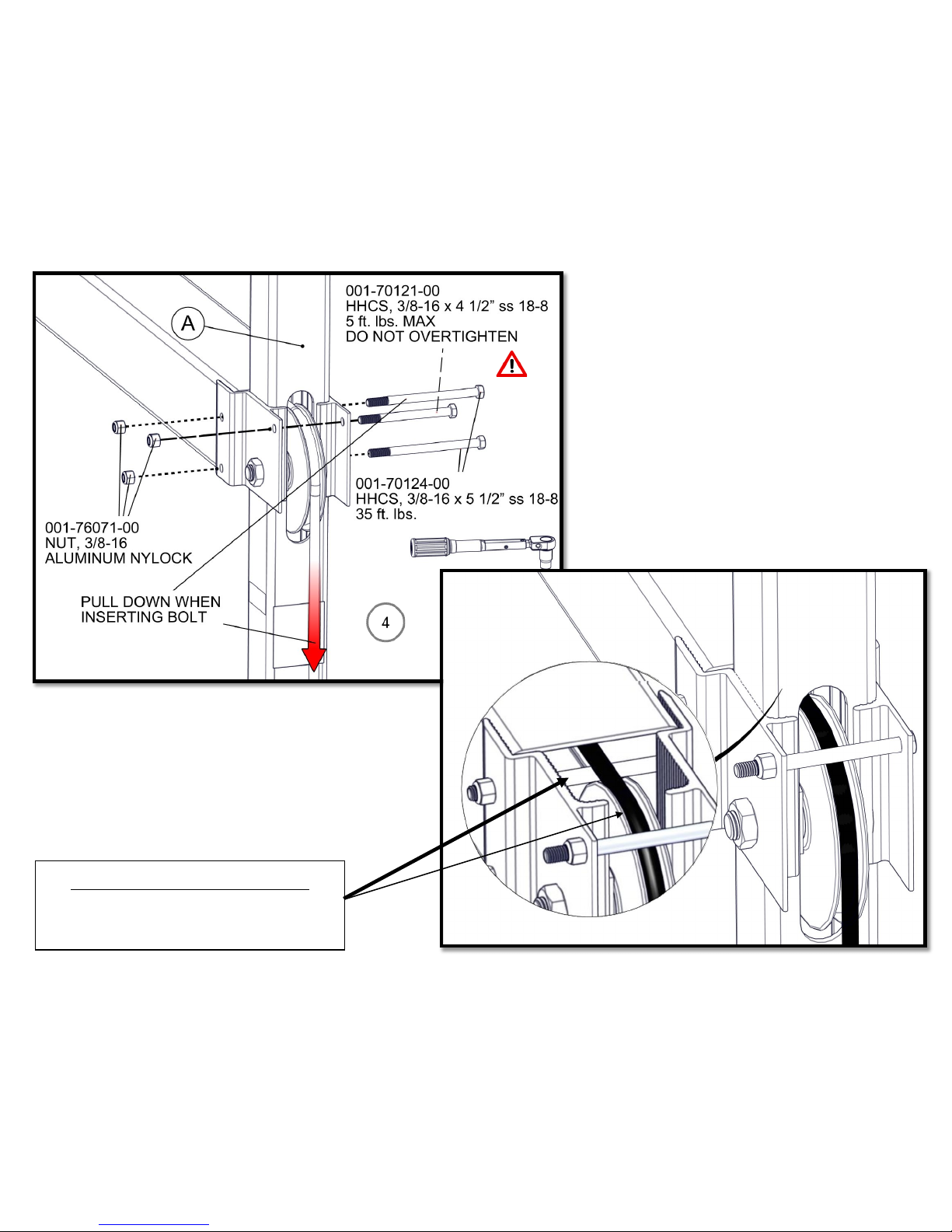
4-I
ASSEMBLY CAUTION NOTE
CABLE MUST BE ABOVE BOLT
AFTER ASSEMBLY
Page 23
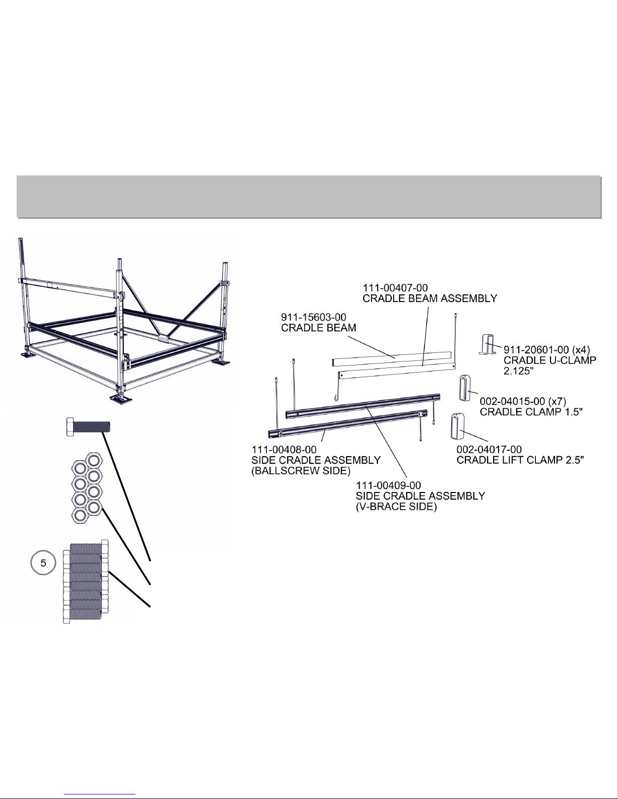
Contents for Step 5
(1) 1/2 x 1 3/4” ss Bolt Torque to 50 ft. lbs.
(8) 1/2” Alum. Nuts
(8) 1/2 x 1 1/2” ss Bolts Torque to 45 ft. lbs.
Page 24
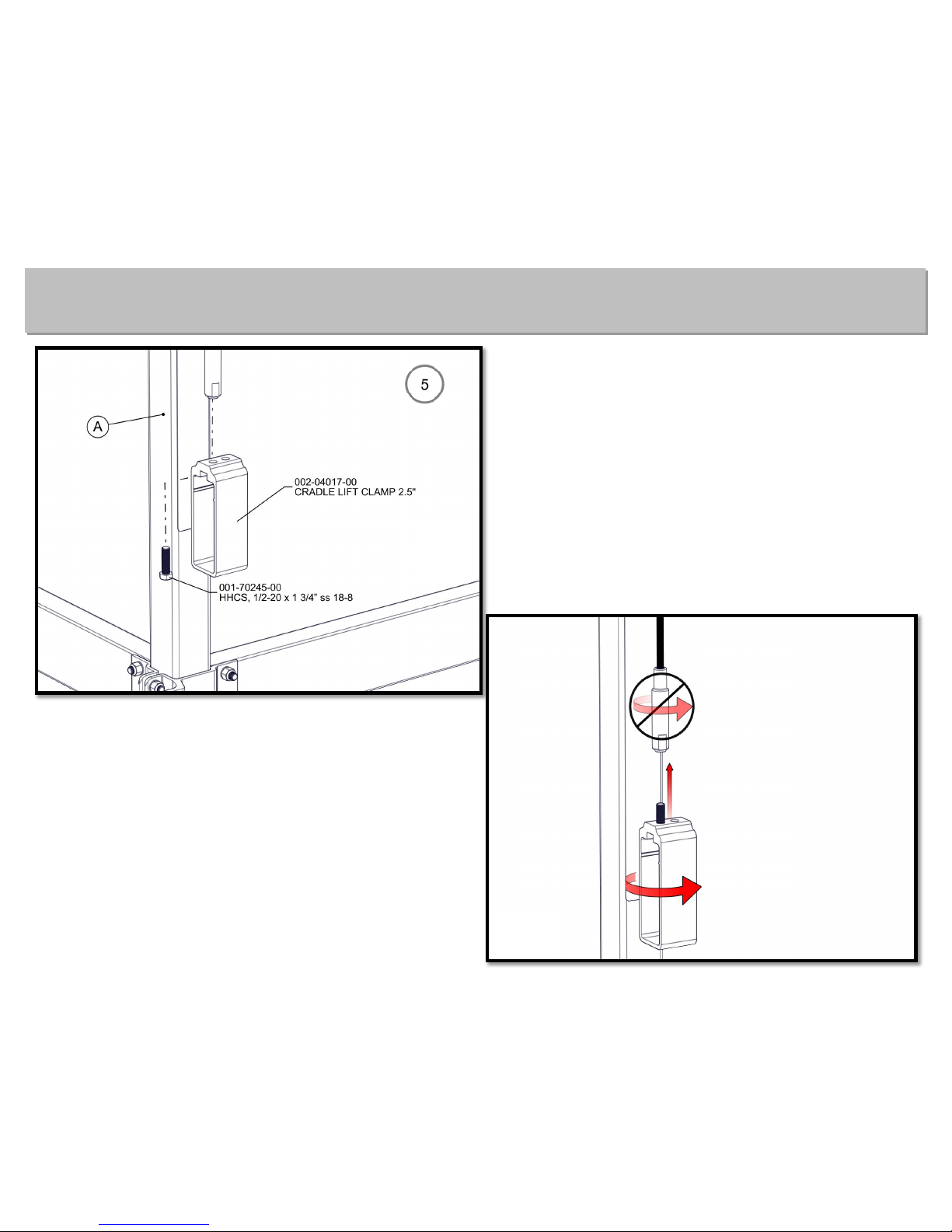
Assembly of Step 5
5-A
5-B
Page 25
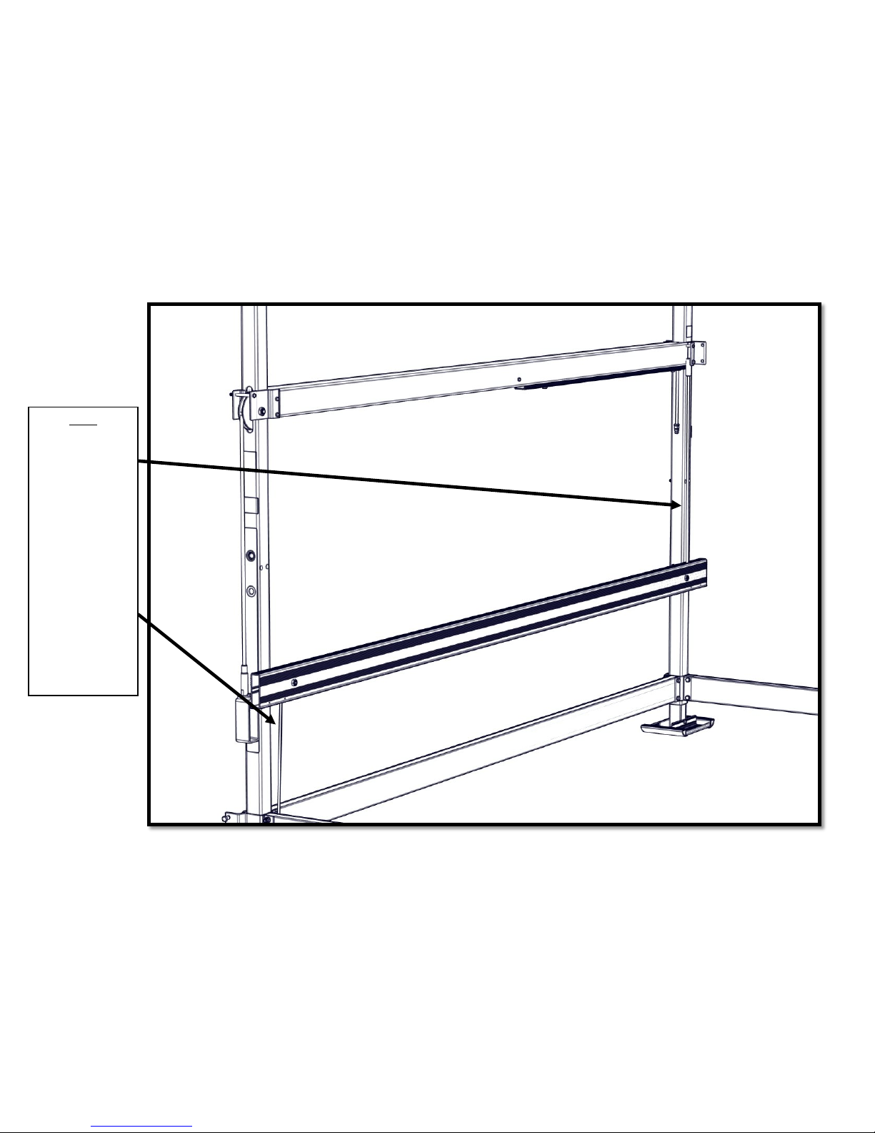
NOTE
LIFTING CABLE
IN UPWARD
DIRECTION IS
PLACED ON
MOTOR SIDE.
LIFTING CABLE
IN
DOWNWARD
DIRECTION IS
PLACED ON
LIFTING
(OPPOSITE)
SIDE.
5-C
Page 26
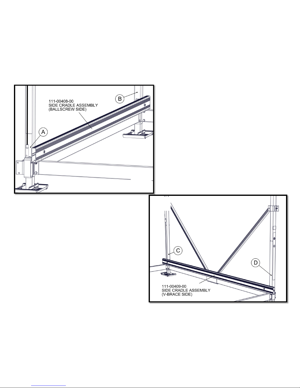
5-E
5-D
Page 27
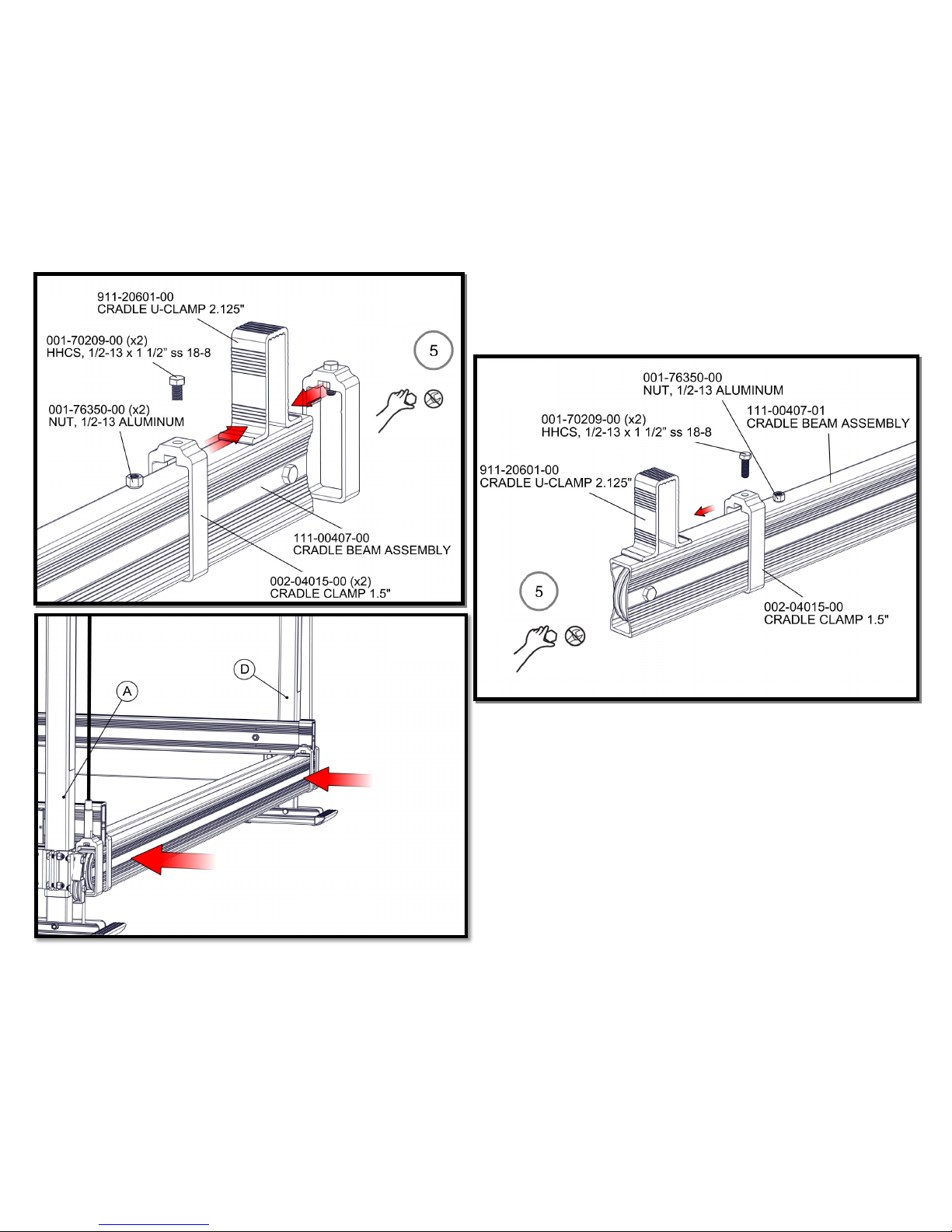
5-F
5-G
5-H
Page 28
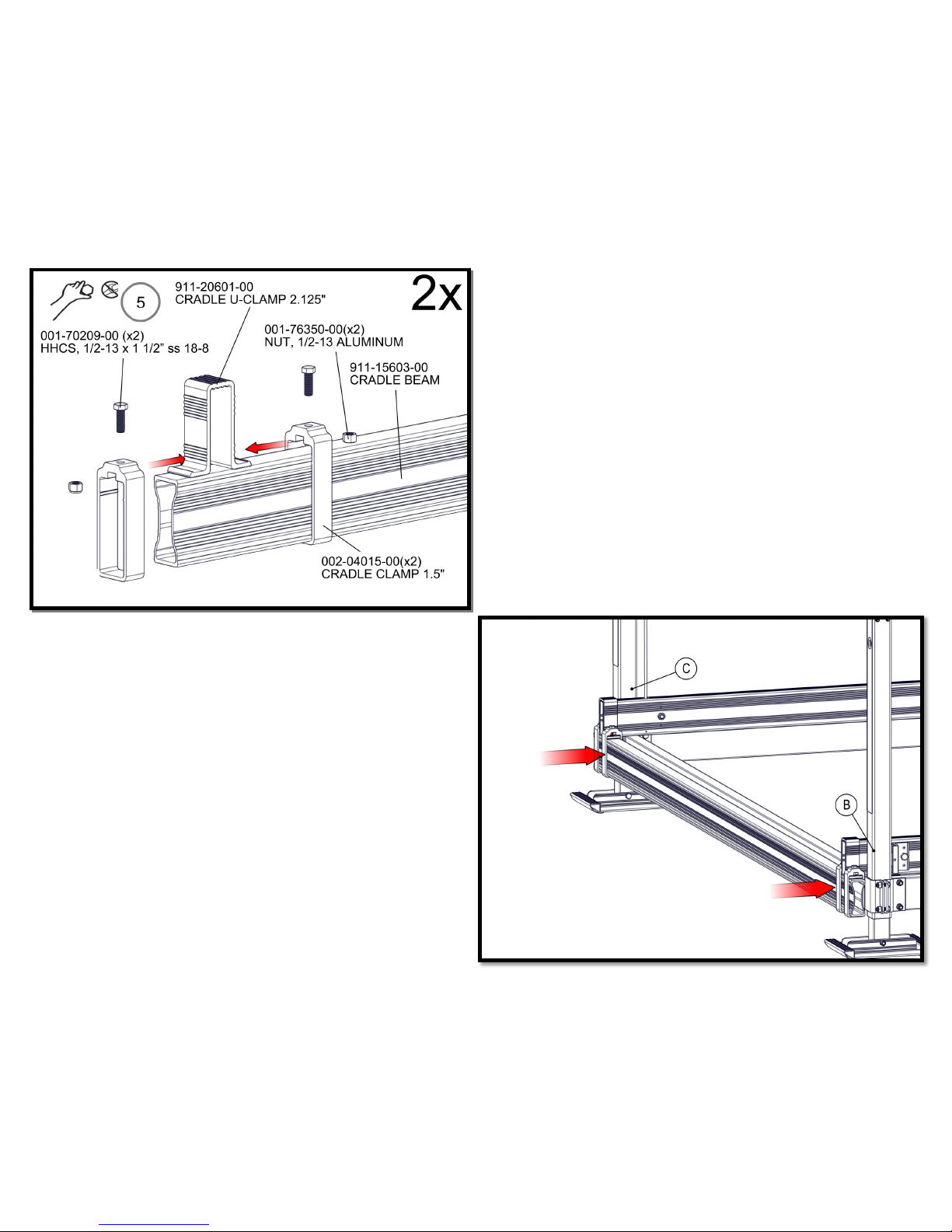
5-I
5-J
Page 29
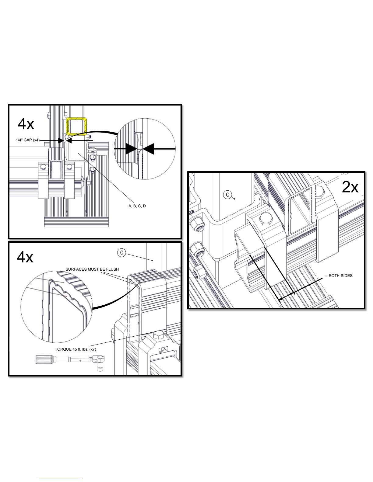
5-K
5-L
5-M
Page 30
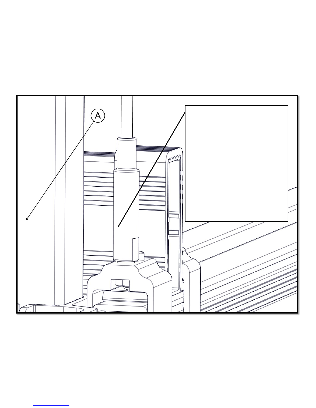
TORQUE TO 50 ft. lbs.
Note:
Torque the lifting clamp while
positioned on the end of the
front cradle beam. Remove
lifting clamp and allow it to
unwind to a neutral position,
then re-install clamp by turning
it in the nearest direction to
properly position clamp back
onto the end of the front cradle
beam. Fasten securely
.
Page 31
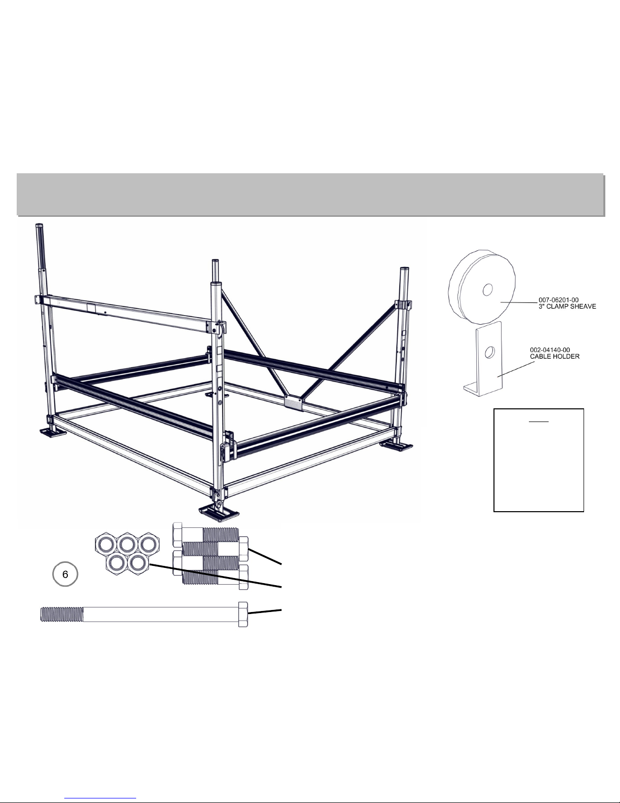
Contents for Step 6
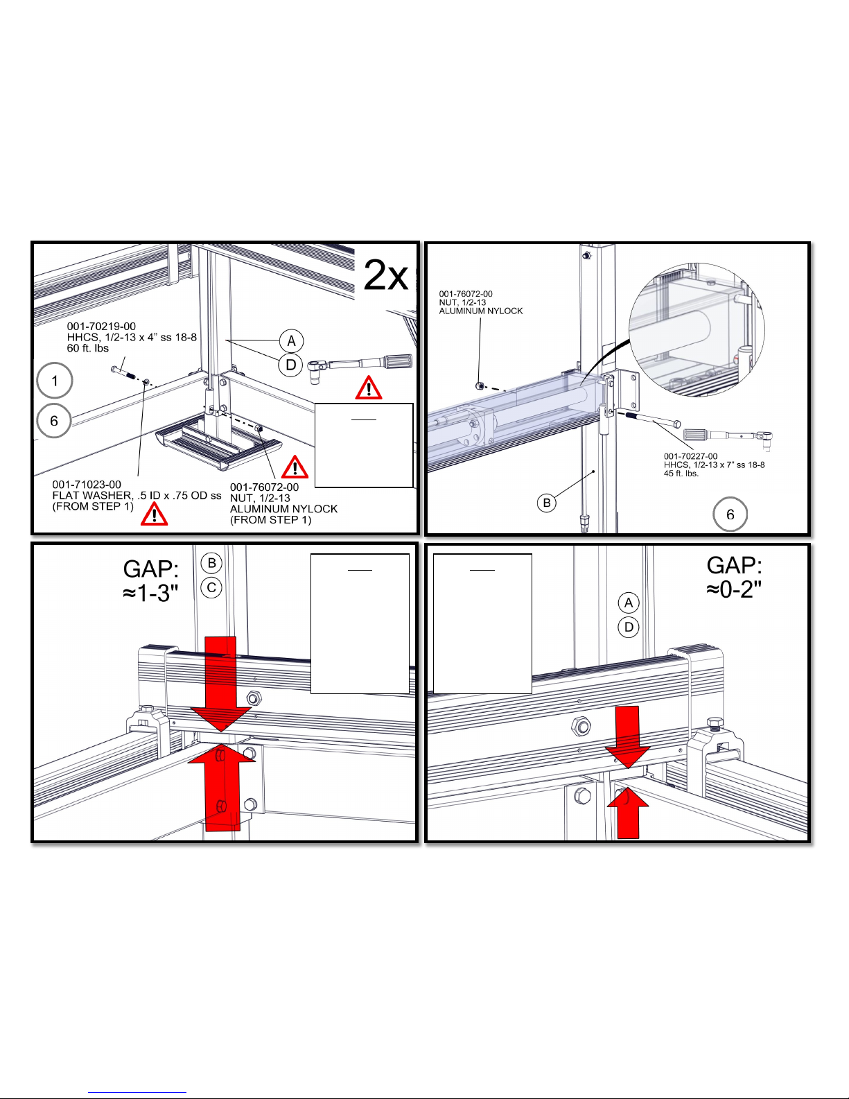
(4) 1/2 x 2” ss Bolts Torque to 45 ft. lbs.
(5) 1/2” Alum. Nylock Nuts
(1) 1/2 x 7” ss Bolt Torque to 45 ft. lbs.
NOTE
Recall (2) ½”
Nylock Nuts and
(2) ½” Washers
from Step 1.
Torque to 60 Ft.
Lbs.
Page 32
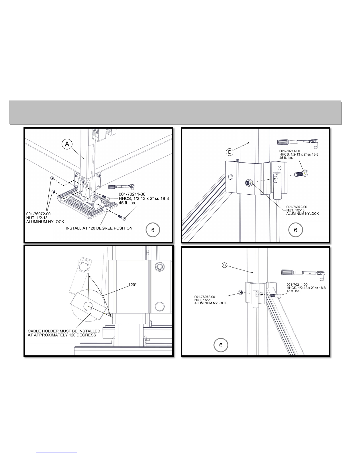
Assembly of Step 6
6-A
6-B
6-C
Page 33
6-D
6-E
NOTE
Recall (2) ½”
Nylock Nuts and
(2) ½” Washers
from Step 1.
NOTE
CHECK
ASSEMBLY OF
LIFT IF GAPS
BETWEEN
CRADLE BEAM
AND FRAME
BEAM ARE
EXTREME.
NOTE
CHECK
ASSEMBLY OF
LIFT IF GAPS
BETWEEN
CRADLE BEAM
AND FRAME
BEAM ARE
EXTREME.
Page 34
Step 7
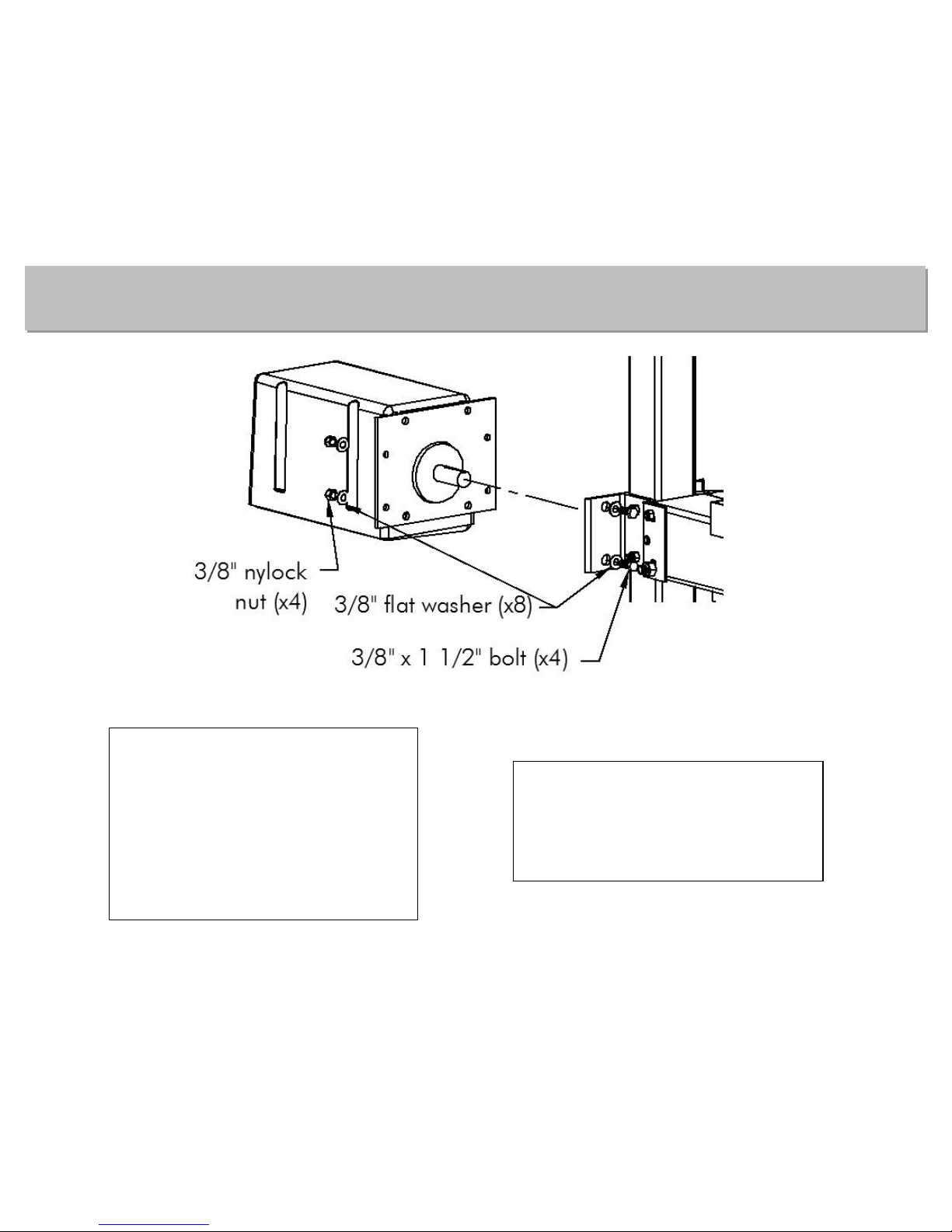
The drive train (SOLD SEPARATELY) can now be
attached to the lift. Note that the rigid coupler
on the drive train and ball screw mate together.
With the drive train being held in place, attach it
to the lift using (4)3/8" x 1 1/2" bolts, (4) nylock
nuts, and (8) flat washers as shown in Fig 7A.
Torque to 10 ft/lbs. Make sure the bolt threads
clear the nylock before using torque wrench.
See Note:
NOTE:
Apply a generous amount of Anti-Seize from
the small packet included, to the inside of the
Rigid Coupler and to the Motor Shaft before
attaching the Drive Unit to the
Lift's Frame.
Page 35
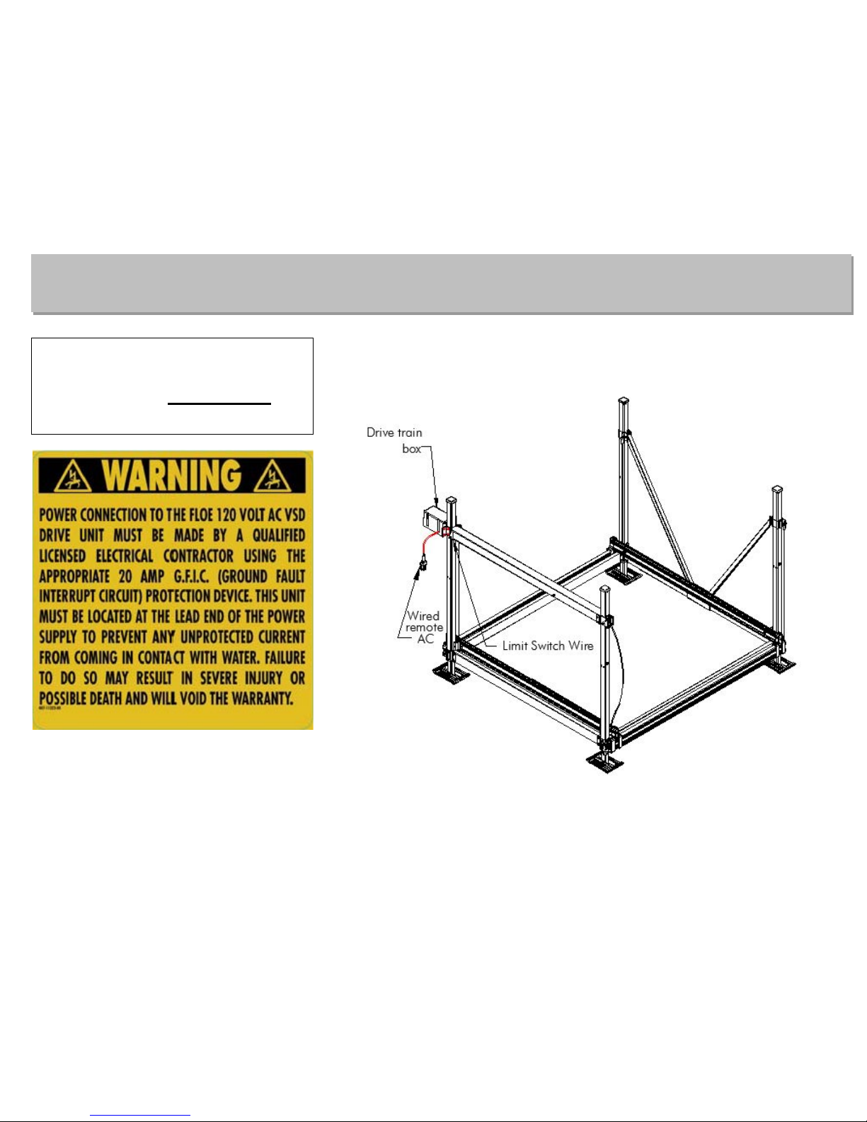
The drive train can now be connected to the
power source. It is very important that this
connection be made in accordance with State
and Local Regulations. SEE WARNING:
STEP 7 AC
Page 36
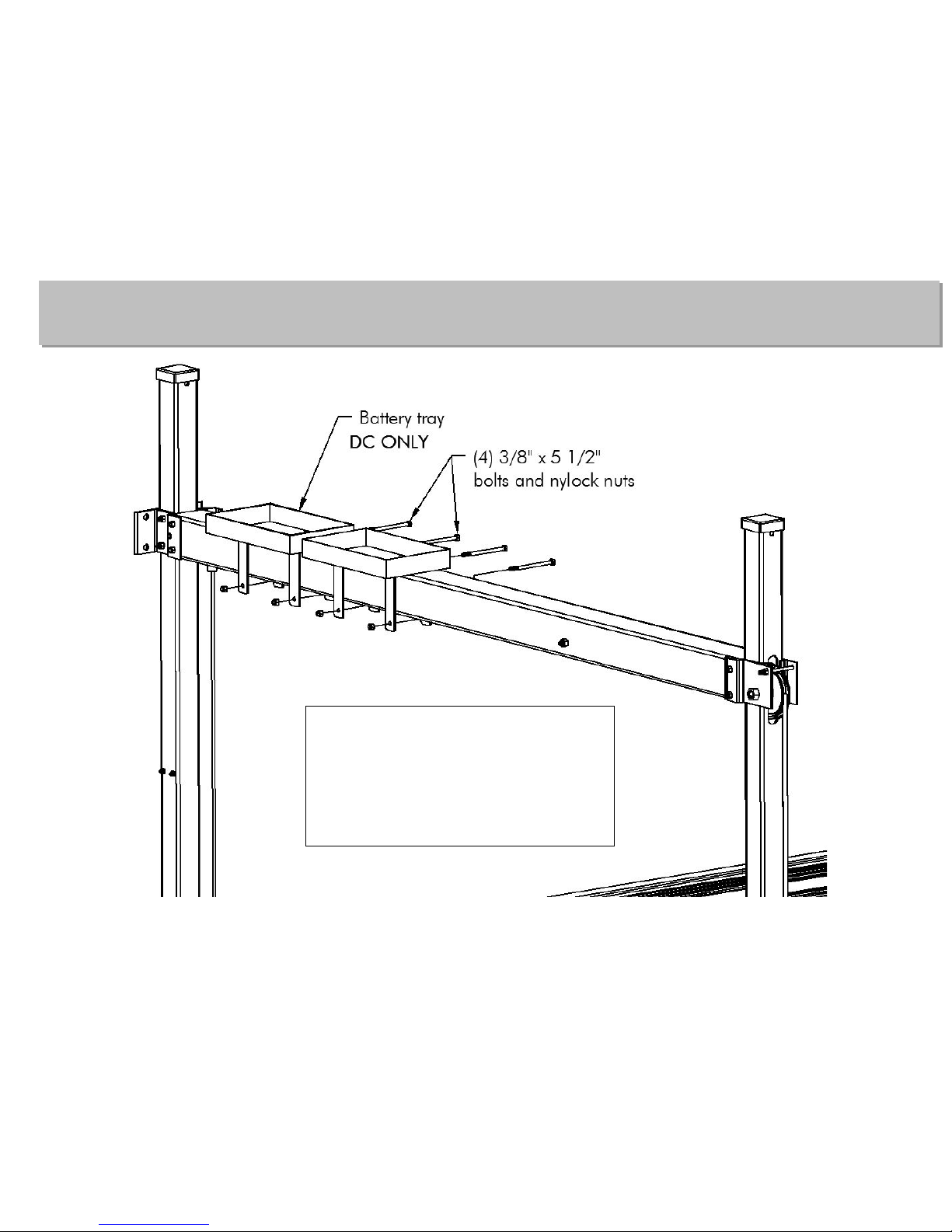
Step 7 DC
DC ONLY
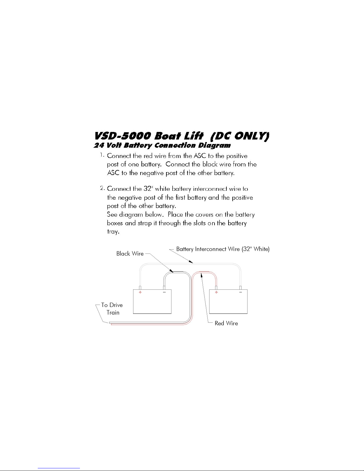
If you purchased the 24 Volt VSD Drive, attach
the battery trays to the ball screw tube using (4)
3/8 x 5 1/2" bolts and nylock nuts. The offset
side of the tray should go to the outside of lift to
provide clearance for the inside of lift.
Page 37
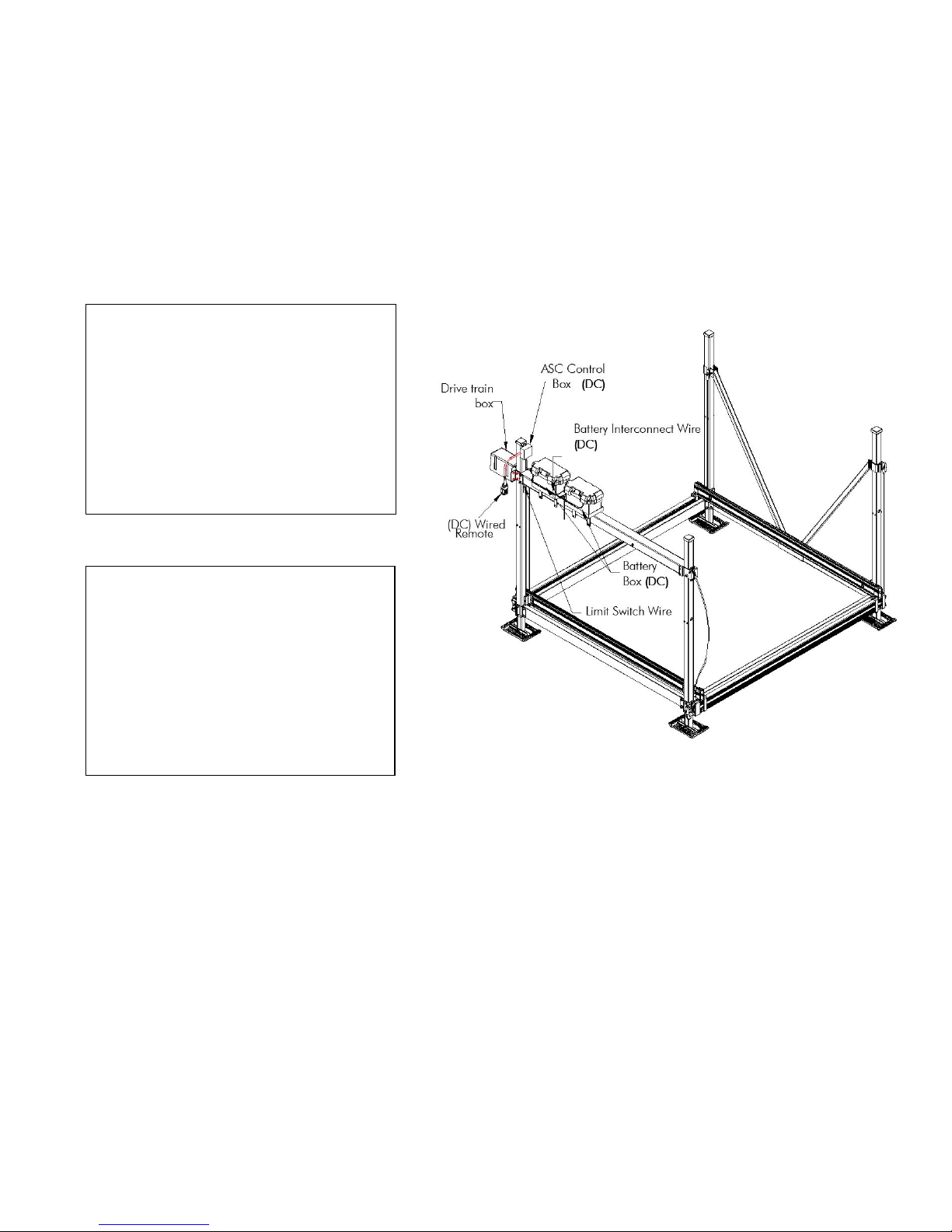
Insert a 12 volt battery into each battery box
(DC ONLY)
. Plug the wired remote into the
plug on the ASC labeled "Wired Remote". Plug
the limit switch wire into the ASC plug Labeled
"Limit Switch". See Fig. 7B. Secure all wires
using the supplied Velcro. If canopy is to be
installed on the lift, the wired remote can be
strung along a canopy hoop and hung next to
the dock and secured to the canopy hoop with
Velcro.
Before installing cap on corner post, insert
1/2"x3/4" bolt through top hole with head inside
post. If lift has canopy, discard 1/2 x 3/4 bolt
that came with the ASC box. Remove nut
from1/2x11/4" bolt holding canopy insert.
Attach ASC box to bolt, install nut, torque to
60ft/lbs with canopy or a1/2 turn past snug for
no canopy. Stick
Dual Lock on corner post, press firmly
together.
Page 38
Page 39

VSD Pre-installation Check List
Prior to installing your lift please follow this
check list to confirm proper operation.
1. Raise the lift up to confirm operation of upper limit switch.
Approach the upper limit switch cautiously by pressing the UP
button in short bursts as you near the top of the lift travel. A
properly working limit switch will stop the lift before the ball
screw reaches its limit of travel. If the limit switch does not
stop the lift and the ball nut reaches the end of the ball screw
you will be able to see the drive unit twisting slightly,
indicating that the motor is trying to run. Also, you probably
would have heard the ball nut hitting the metal stop at the
end of the screw. The brake will still click when stopped at
the limits.
2. Lower the lift down to confirm operation of lower limit
switch. Again, as you approach the bottom of the lift travel
press the DOWN button in short bursts. The lift should stop
with a small amount of slack in the lifting cable after the
cable contacts the lift frame. If the limit switch does not stop
the lift and the ball nut reaches the end of the ball screw you
will be able to see the drive unit twisting slightly indicating
that the motor is trying to run. Also, you probably would
have heard the ball nut hitting the metal stop at the end of
the screw.
If either limit switch does not stop the lift
correctly, contact FLOE customer service and do
not use the lift until the problem is corrected.
3. Listen for unusual noises during lift operation. Squeaking
may indicate that the lift may not have been greased. Both
the thrust bearing and the ball nut MUST be greased before
using the lift. Please see owners' manual for details.
4. If you have a wireless remote it would be good idea to
test it at this time. There is no need to go all the way to the
limit switches since those were tested above. Also check the
inside (amber) light and the mast light if you have one. The
lights come on when their buttons are pressed and go off
with a second press or after about 7 minutes of no light
button activity.
Page 40
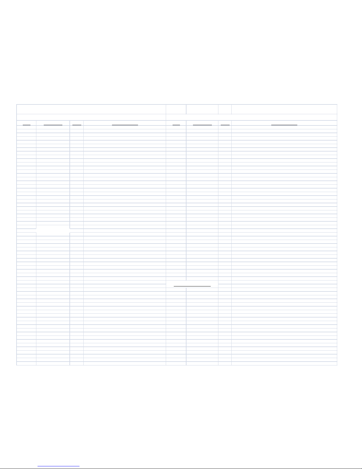
VS D- 5000 Pontoon L IFT
NO.
PART NO.
QTY.
DESCRIPTION
NO.
PART NO.
QTY.
DESCRIPTION
1 002-04015- 00 7 CRADLE CLAMP 1.5" 59 001-70211- 00 4 HHCS, 1/2-13 X 2" SS 18-8
2 002-00038- 01 2 SIDE FR AME BE AM 144" ( .125) 60 001-70217- 00 14 HHCS, 1/2-13 X 3 1/2" SS 18-8
3 002-04017- 00 1 CRADLE LIF T CLAMP 2.5" 61 001-70218- 00 4 HHCS, 1/2-13 X 3 3/4" SS 18-8
4 002-00006- 00 2 F/R FR AM E BE AM 122" (. 125) 62 001-70221- 00 2 HHCS, 1/2-13 X 4 1/2" SS 18-8
5 002-00034- 01 2 V-B RACE 92.312" 63 001-70215- 00 2 HHCS, 1/2-13 X 3" SS 18-8
6 002-04031- 00 4 CRADLE GUIDE 64 001-70227- 00 1 HHCS, 1/2-13 X 7" SS 18-8
7 002-00001- 00 2 BRACKET,UPPER LFTG./V-BRACE 65 001-70310- 00 2 HHCS, 5/8-11 X 1 3/4" SS 18-8
8 001-70117- 00 2 HHCS, 3/8-16 X 3 1/2" 18-8 SS 66 001-70313-00 4 HHCS, 5/8-11 X 2 1/2" SS 18- 8
9 002-00002- 00 2 BRACKET, UPPER V-BRACE - 4" 67 001-16369- 00 1 HHCS, 3/4-16 X 4" GRADE 5 PLA IN
10 002-04040- 00 2 SIDE CRADLE 109" 68 001-70817- 00 2 NUT, JA M 3/4- 10 SS 18-8
11 001-40365- 00 1 FLA TWA SHER , M 24 ZIN C 69 001-70816- 00 6 NUT, JA M 5/8- 11 SS 18-8
12 002-00057- 01 1 FR ONT CR ADLE BE AM 127" (. 145) 70 001-70861- 00 8 NUT, JA M 5/16- 18 ALU MIN UM NYLOCK
13 002-04064- 00 1 V-BRACE CLAMP (FEMALE) 71 001-71017- 00 8 3/8" SAE FLA T WA SHE R
14 002-04066- 00 1 V-BRACE CLAMP (MALE) 72 001- 71021-00 19 1/2" F LAT W ASH ER SAE SS 18-8
15 002-00005- 00 4 FRAME BEAM CLAMP (INNER) 73 001- 71022-00 32 1/2" FLAT W ASH ER USS SS 18-8
16 002-00003- 00 3 FRAME BEAM CLAMP ( OUTER) 74 001-26969- 00 4 PIN , G ROOV E 5/32" X 1 1/ 8" ZINC
17 002-00004- 00 1 FRAME BEAM WINCH CLAMP 75 001-26911- 00 4 DOWE L P IN 3/16" X 7/8"
18 002-04140- 00 1 CABLE HOLDER 76 001- 74402-00 8 CARRIAGE BOLT, 5/16- 18 X 3 1/2" SS 18- 8
19 002-04314- 00 4 LEVEL LEG BRACKET (3") 77 001-71024- 00 16 FLA TWA HER , 5/8" X 1 1/4" X .060" SS
20 002-00067- 01 1 CORN ER POST 89. 5" LIF TING (. 188) 78 001-76071- 00 13 NUT, 3/8- 16 ALUM IN UM N YLOCK
21 002-00070- 01 1 CORN ER POST 89. 5" MOTOR (. 188) 79 001-76072-00 44 NUT, 1/2- 13 ALU MIN UM N YLOCK
22 002-00071- 01 2 CORN ER POST 89. 5" (. 188) 80 111-00248-00 1 BALL N UT BLOCK ASSE MBLY
23 111-00410- 02 1 BALL SCREW TUBE WELDMENT 81 001-73454-00 1 SHCS, 10-32 X 1 3/4" SS 18- 8
24 002-04306- 01 1 3" BALL SCRE W CLAM P 82 001-76073- 00 1 NUT, 10-32 A LUM INU M N YLOCK
25 002-04307- 00 1 3" PULLE Y CLAMP (OUTER) 83 001-93524- 00 1 NUT, SLOTTE D M24 X 1. 5
26 002-04308- 00 1 3" PULLE Y CLAMP (INNER) 84 001-70245- 00 1 HHCS, 1/2-20 X 1 3/4" SS 18-8
27 111-00000- 00 4 SAND PAD 85 001-76069- 00 8 5/8" FLA T WA SHE R - NYLON
28 111-00216- 01 4 WE LD'T, INNE R LEG 4000- 5000 86 007-05223-00 1 RIG ID COUPLER
29 111-15603- 00 1 CRADLE B EAM 127" (.145) 87 007-05242- 00 1 3/16" SQ. X 2" KE Y
30 911-20601- 00 4 CRADLE U -CLAMP 2.125" 88 111-38500- 00 1 LIMI T SWITCH ASS' Y 3800/5000
31 006-10202- 00 4 CRADLE GUIDE WEAR PAD 89 001-70203- 00 2 HHCS, 1/2-13 X 3/4" SS 18-8
32 006-10206- 00 8 SIDE CRADLE SHEAVE SPACER 90 007-05126-00 1 M 8 X 1 GREASE ZE RK (FLUSH )
33 006-11001- 00 4 UHMW - 3/16" X 1/2" X 5" LG . 91 001-70124- 00 2 HHCS, 3/8-16 X 5 1/2" SS 18-8
34 006-15200- 00 3 3" CORN ER POST CA P 92 001- 71023-00 16 FLAT W ASHE R, .5 ID X .75 OD SS
35 007-04154- 00 1 3/4" SHEAVE PIN 93 911-14201- 00 1 ADJ USTABLE IN SER T
36 111-00311- 00 1 ASS'Y BEA RIN G BLOCK W/BEAR ING 94 006-15022-00 1 CAP , VINYL - CA NOPY / WIN CH INSERT
37 007-05013- 00 1 BALL SCRE W E ND STOP PLATE 95 006-10021- 00 1 UHMW BALLSCREW SUPT. SLEEVE
38 007-05023- 00 4 TOP BEVEL GEAR - 1:1 96 006-22202- 00 1 STEE L SLEE VE 1" X 2.25" LG
39 007-15024- 00 4 BOTTOM BEVEL GEA R -( FAB) 97 001- 70209-00 8 HH CS, 1/2- 13 X 1 1/2" SS 18- 8
40 007-05079- 00 4 BEVEL GEAR ADJUSTMENT SCREW 98 007-07707- 00 2 SPA CER , P ULLE Y 3800/5000
41 007-06201- 00 1 3" CLAM P SHEAV E 99 002-03323- 00 4 PLATE, 1 X 2" X 3/16" THK ( WE LDE D TO COR NE R P OST)
42 111-00201- 00 1 ASS'Y , 6" LIF TIN G SHE AVE
43 007-07700- 00 4 SPA CER TUBE - 1. 297"
44 007-07701- 00 2 SPA CER TUBE - 1. 055"
45 007-09004- 00 2 SIDE LEVE LIN G CA BLE - 214. 125" 100 111-00408- 00 SIDE CRAD LE A SSEMBLY ( A)
46 007-09350- 00 1 FR ONT LE VELING CAB LE - 207.250" INCLU DE S ITEM S 6, 10, 31, 32, 33, 43, 45, 49, 66, 69
47 007-09149- 00 1 LIFTI NG CABLE 150.750" 101 111-00409-00 SID E CR ADLE ASSE MBLY (B)
48 011-15005- 00 1 1727mm BALL SCRE W 40- 10-m m W/N UT INCLU DE S ITEM S 6, 10, 31, 32, 33, 43, 45, 49, 66, 69
49 111-00107- 00 6 5" SHEAVE W/BUSHING 102 111- 00407-01 F RON T CRA DLE ASSEMBLY ( .145)
50 001-70123- 00 1 HHCS, 3/8-16 X 5" 18-8 SS INCLU DE S ITEM S 12, 44, 46, 49, 65, 69
51 001-23876- 00 1 SHCS, 1/ 2-20 X 1 1/4" BLACK 103 111- 00431-02 V5000 COR NE R P OST ASSY (A )
52 001-33092- 00 1 FLA T WA SHER , SA E 3/4" Z INC INCLU DE S ITEM S 20, 25, 26, 34, 35, 42, 68, 70, 76, 105
53 001-70109- 00 4 HHCS, 3/8-16 X 1 1/2" SS 18-8 104 111-00418- 02 V5000 CORN ER POST A SSY ( B)
54 001-70115- 00 4 HHCS, 3/8-16 X 3" SS 18-8 INCLU DE S ITEM S 22, 34, 70, 76, 105
55 001-70121- 00 3 HHCS, 3/8-16 X 4 1/2" SS 18-8 105 111-00419- 02 V5000 CORN ER POST A SSY ( C)
56 001-70210- 00 8 HHCS, 1/2-13 X 1 3/4" SS 18-8 INCLU DE S ITEM S 22, 34, 70, 76, 105
57 001-70127- 00 1 HHCS, 3/8-16 X 7" SS 18-8 106 111-00420- 02 V5000 CORN ER POST ASSY ( D)
58 001-70207- 00 1 HHCS, 1/2-13 X 1 1/4" SS 18-8 INCLU DE S ITEM S 22, 34, 70, 76, 105
107 111-00234-01 ASS' Y, INN ER LEG 4600-5000
INCLU DE S ITEM S 19, 28, 38, 39, 40, 72, 74, 75, 77, 85
108 111-00412-02 3800/5000# B ALL SCR EW TUBE ASSE MBLY
INCLU DE S ITEM S 11, 23, 36, 37, 47, 48, 50, 51, 52, 63,
67, 78, 79, 80, 83, 86, 87, 88, 89, 90, 95, 96
109 111-00411-01 CAN OPY/WIN CH POST
INCLU DE D ITE MS 58, 72, 79, 93, 94
LIFT P /N 511-50085- 01
SUB-ASSEMBLIES
Page 41
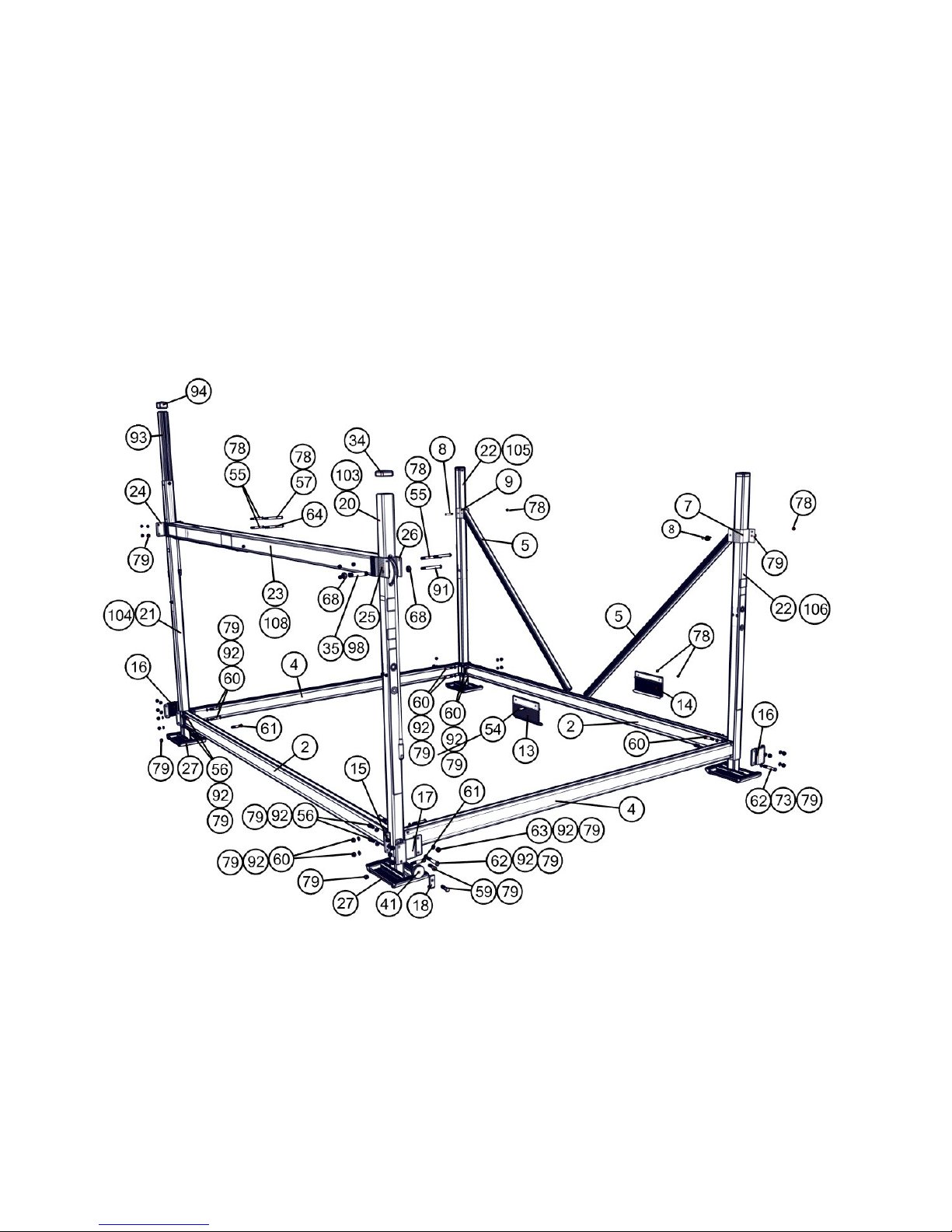
VSD 5000 Pontoon Frame Exploded View A
LIFT P/N 511-50085-01
Page 42
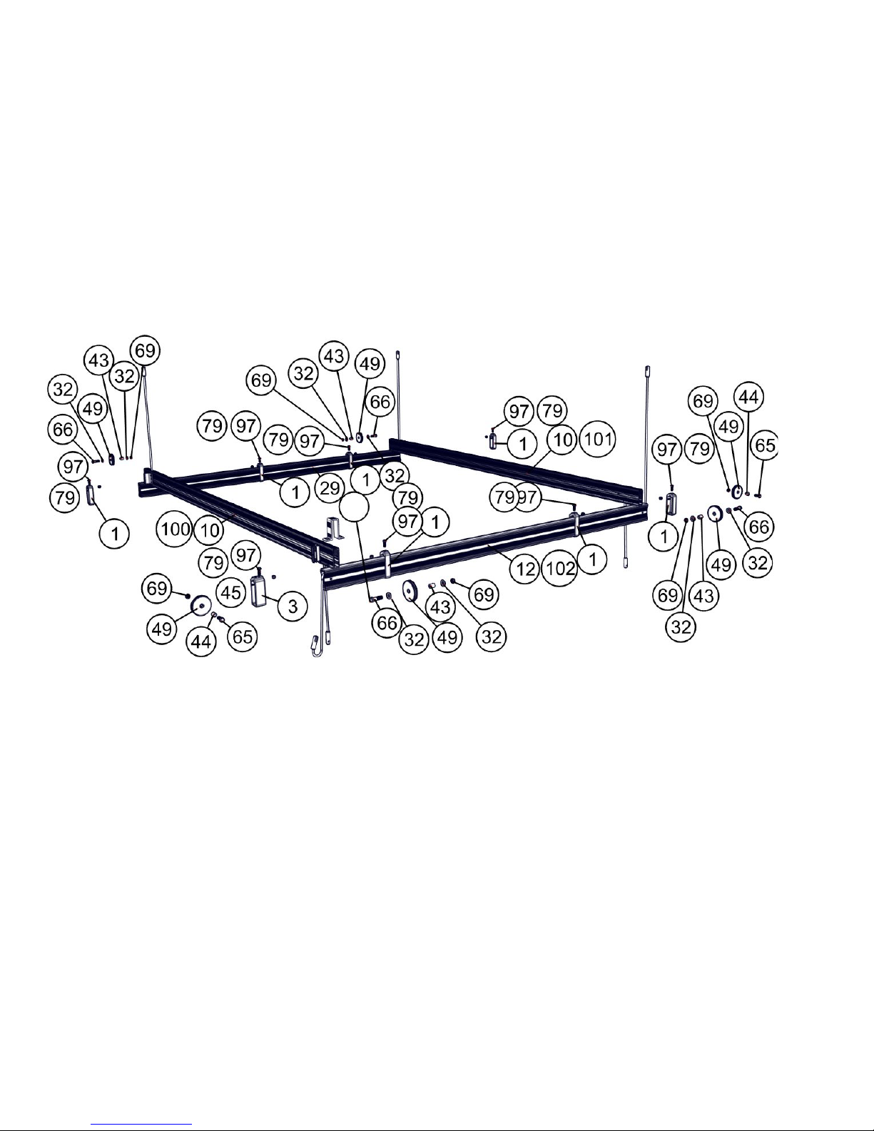
VSD 5000 Pontoon Frame Exploded View B
LIFT P/N 511-50085-01
Page 43
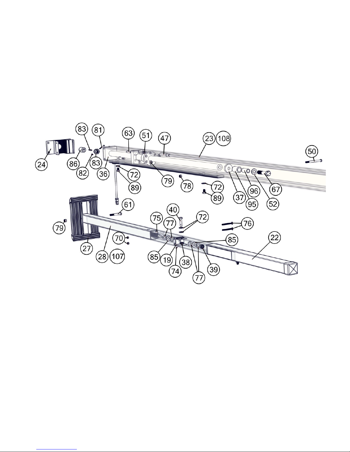
VSD 5000 Pontoon Frame Exploded View C
LIFT P/N 511-50085-01
Page 44

 Loading...