

Floe VSD 3800 Assembly Instructions Manual

FLOE VSD
38
00 BOAT LIFT
P/N 511-38075-01 LIFT FRAME
WITH PATENTED EASY LEVEL LEG SYSTEM
ASSEMBLY INSTRUCTIONS
©Manufactured by:
Floe International Inc.
48473 State Hwy. 65
McGregor, MN 55362
www.floeintl.com
In
struction P/N 611
-
38075
-
01 Rev H
Issued 5/7/2018
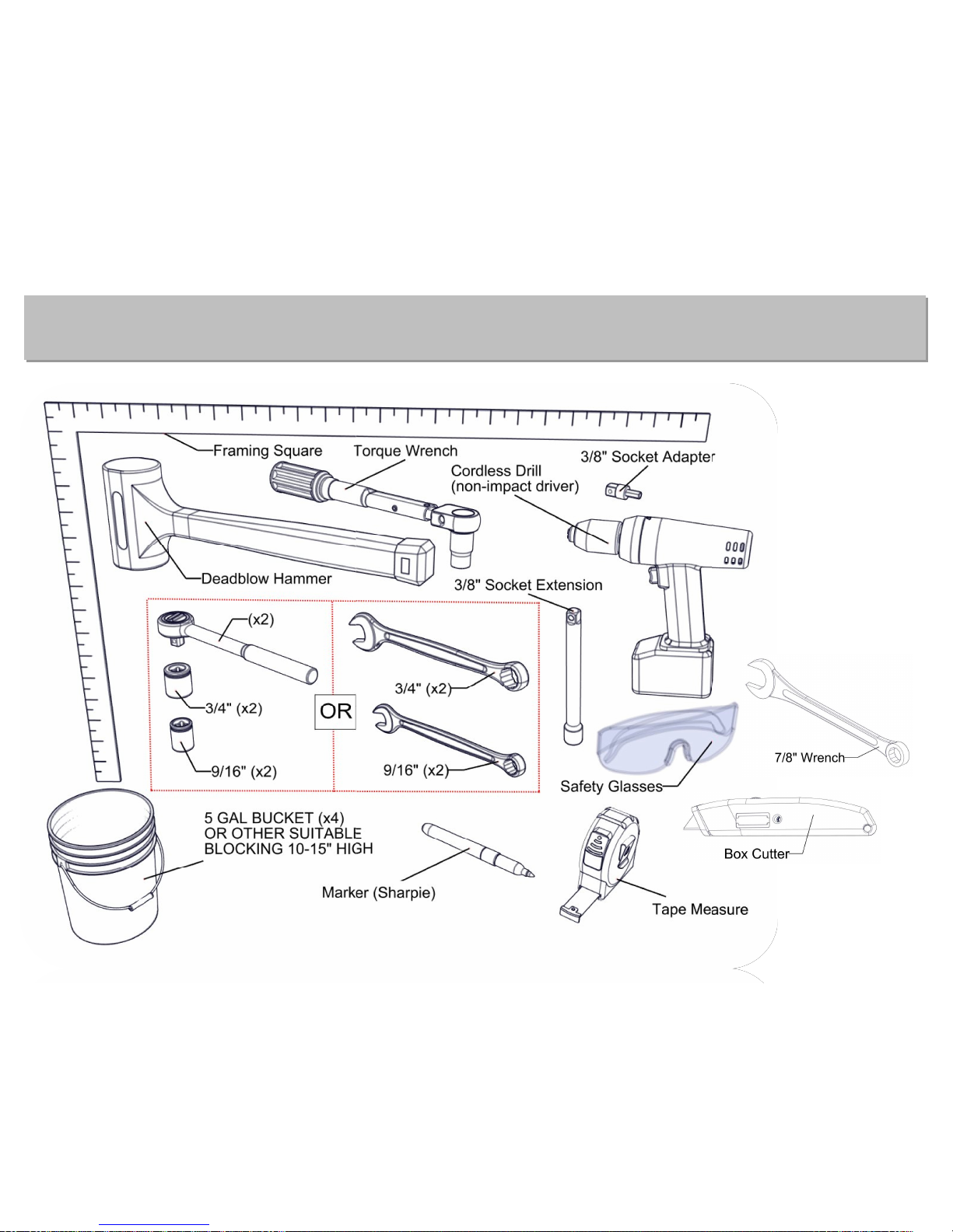
Required Tools
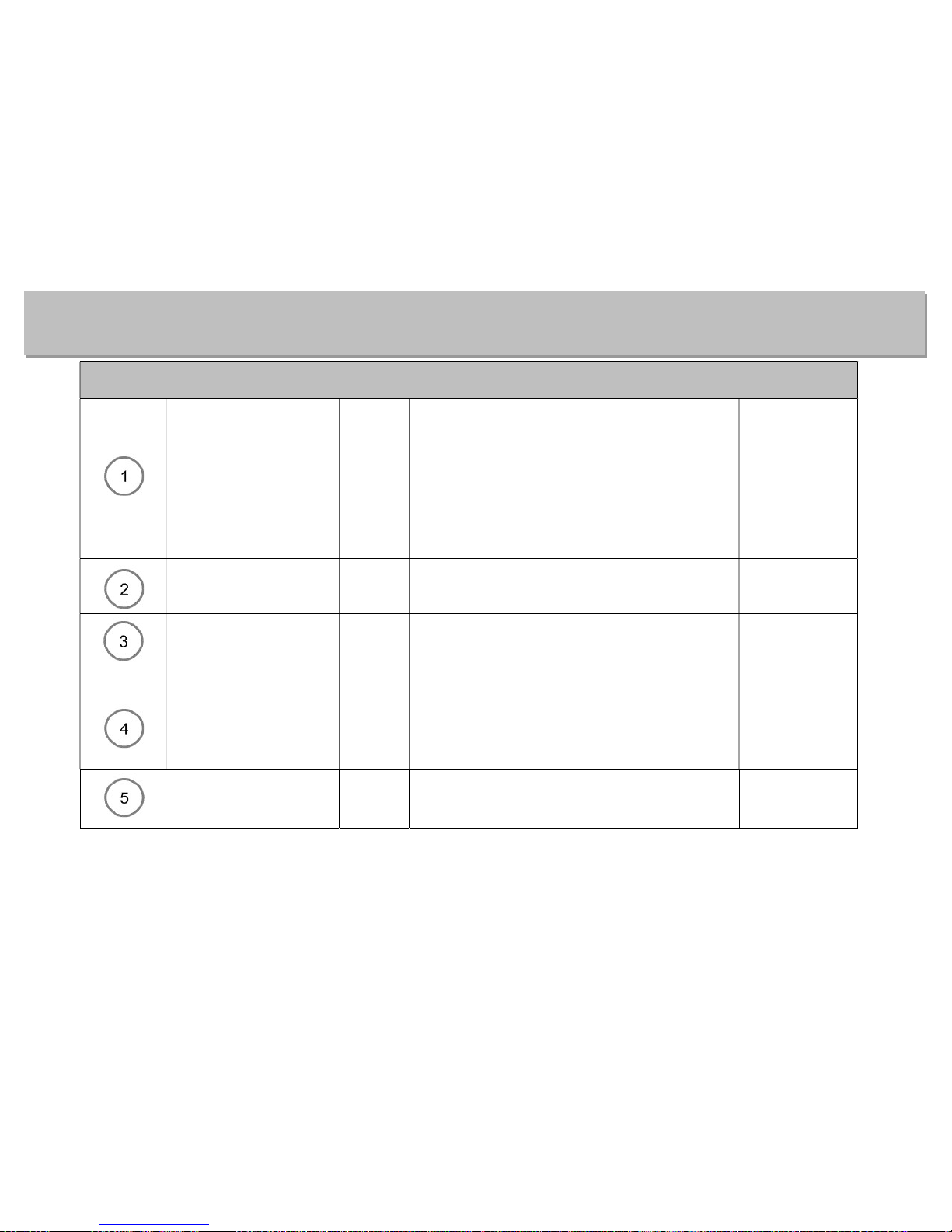
Card Contents (511-04255-00)
Step
Part Numbers
QTY Descriptions Torques
001-70215-00
001-70217-00
001-70210-00
001-70219-00
001-71023-00
001-76072-00
6
8
8
2
48
24
HHCS, 1/2-13 x 3” ss 18-8
HHCS, 1/2-13 x 3 1/2” ss 18-8
HHCS, 1/2-13 x 1 3/4” ss 18-8
HHCS, 1/2-13 x 4” ss 18-8
FLAT WASHER, .5 ID x .75 OD ss
NUT, 1/2-13 ALUMINUM NYLOCK
60 ft. lbs.
45 ft. lbs.
45 ft. lbs.
60 ft. lbs.
001-70218-00
001-76072-00
4
4
HHCS, 1/2-13 x 3 3/4” ss 18-8
NUT, 1/2-13 ALUMINUM NYLOCK
20 ft. lbs.
001-76071-00
001-70115-00
001-70117-00
8
4
4
NUT, 3/8-16 ALUMINUM NYLOCK
HHCS, 3/8-16 x 3” ss 18-8
HHCS, 3/8-16 x 3 1/2” ss 18-8
35 ft. lbs.
001-70124-00
001-70127-00
001-76071-00
001-70121-00
2
1
6
3
HHCS, 3/8-16 x 5 1/2” ss 18-8
HHCS, 3/8-16 x 7” ss 18-8
NUT, 3/8-16 ALUMINUM NYLOCK
HHCS, 3/8-16 x 4 1/2” ss 18-8
35 ft. lbs.
35 ft. lbs.
35 ft. lbs.
001-70209-00
001-70245-00
001-76350-00
8
1
8
HHCS, 1/2-13 x 1 1/2” ss 18-8
HHCS, 1/2-20 x 1 3/4” ss 18-8
NUT, 1/2-13 ALUMINUM
45 ft. lbs.
50 ft. lbs.
Hardware Card Contents
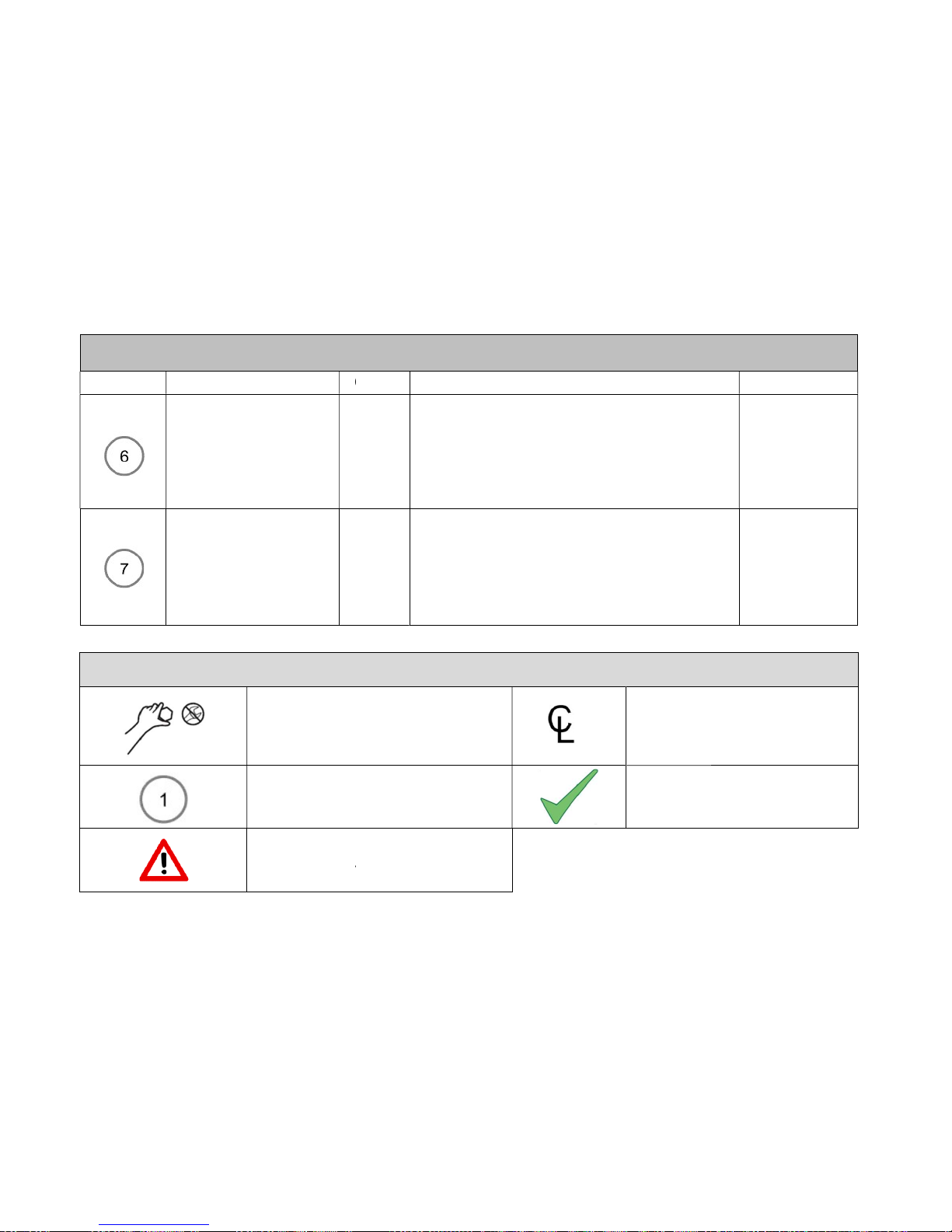
Step
Part Numbers
QTY
001-70211-00
001-76072-00
001-70227-00
002-04140-00
007-06201-00
001-70109-00
001-71017-00
001-76071-00
001-70124-00
001-76071-00
Assembly
Tighten without Clamping
Hardware Card #
Important Notice
continued
QTY
Descriptions
4
5
1
1
1
HHCS, 1/2-13 x 2” ss 18-8
NUT, 1/2-13 ALUMINUM NYLOCK
HHCS, 1/2-13 x 7” ss 18-8
CABLE HOLDER
3” CLAMP SHEAVE
4
8
4
4
4
HHCS, 3/8-16 x 1 1/2” ss 18-8
3/8” SAE FLAT WASHER
NUT, 3/8-16 ALUMINUM NYLOCK
HHCS, 3/8-16 x 5 1/2” ss 18-8
NUT, 3/8-16 ALUMINUM NYLOCK
Image Definitions
Centerline
Check, Inspect, Verify
Torques
45 ft. lbs.
45 ft. lbs.
10 ft. lbs.
35 ft. lbs.

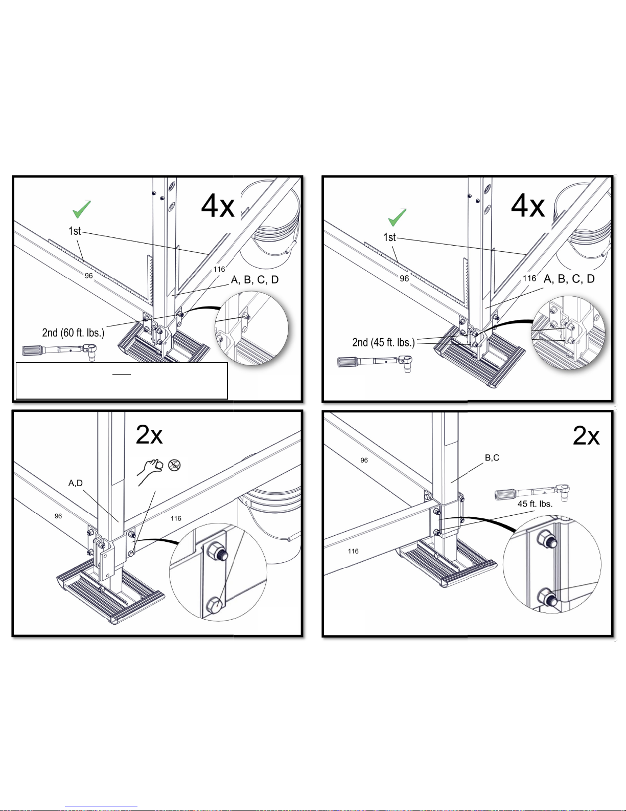
Torque nuts to specification, not bolts.
Place parts and fasteners in designated locations prior to each step.
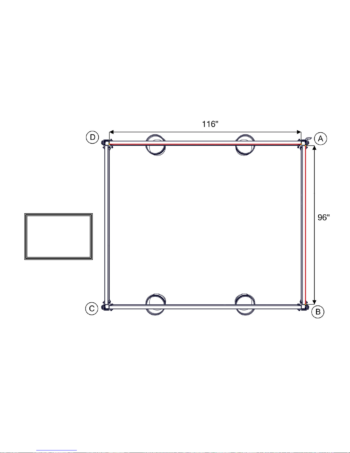
Before tightening fasteners to specified torque, ensure that the lift is square.
Measure from corner to corner (A to C/B to D) to verify that the lift is square.
Measure distance between corner posts (A to B, B to C, C to D, A to D) above frame beam and at the
top of the corner post to verify that the lift is square.
Ensure that the lift is level and square before proceeding to install the V-Brace or Ball Screw Tube.
Assemble cradle clamps with given bolt and nut before installing onto cradle beam.
Use a marker to denote fasteners which have been tightened to the specified torque.
Read instructions and understand them before attempting assembly.
IMPORTANT NOTE:
DO NOT USE IMPACT WRENCH
WHEN ADJUSTING THE EASY
LEVEL LEGS
Warnings
Tips
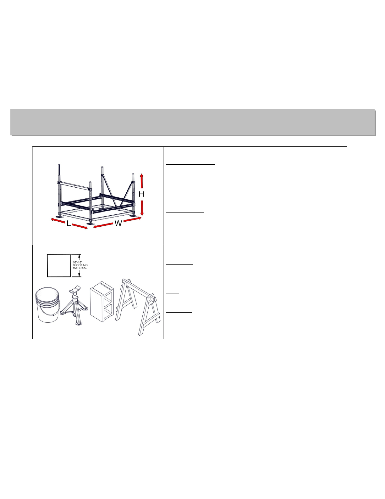
Lift Dimensions
Length: 114”
Width: 130”
Height: 120”
Work Space
Level work space
Allow space to organize parts
Material
Blocking may be anything 10”-15” in height.
(5 gallon bucket, jack stands, blocks, saw horses)
QTY
4 (2 for each side)
Purpose
Blocking used to support lift during assembly steps
1 and 2
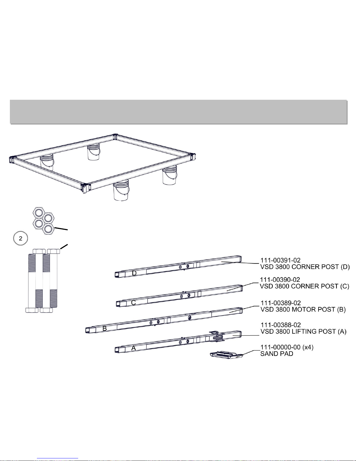
Pre-Assembly Prep
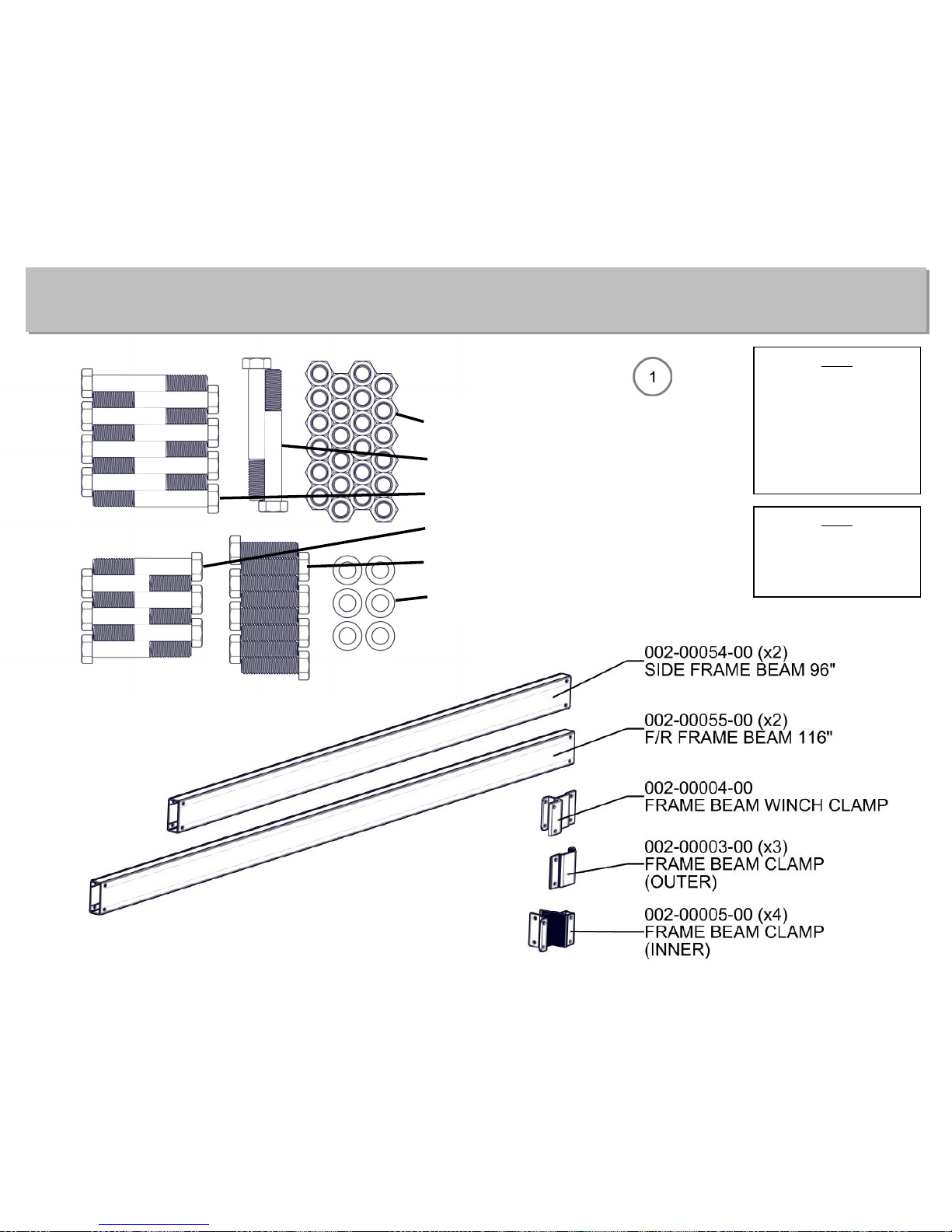
Contents for Step 1
(24) 1/2” Alum. Nylock Nuts
(6) 1/2 x 4” ss Bolts
(8) 1/2 x 3 1/2” ss Bolts
(6) 1/2 x 3” ss Bolts
(8) 1/2 x 1 3/4” ss Bolts
(48) 1/2” ID x 7/8” OD ss Washers
NOTE
(2) ½” Nylock Nuts
and (2) ½” Washers
are used in Step 6-D
to attach lifting
cables to (2) ½” x 4”
Bolts.
NOTE
ALL FASTENERS IN
STEP 1 ARE HAND-
TIGHTENED ONLY.
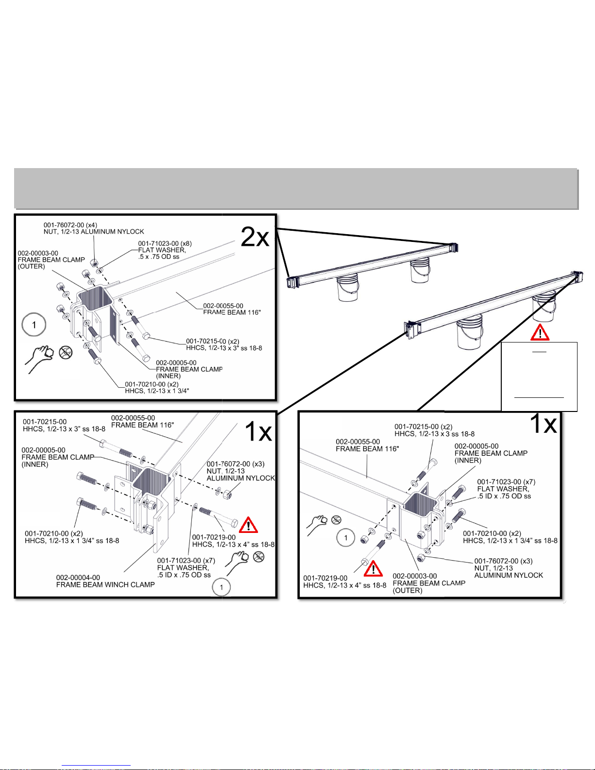
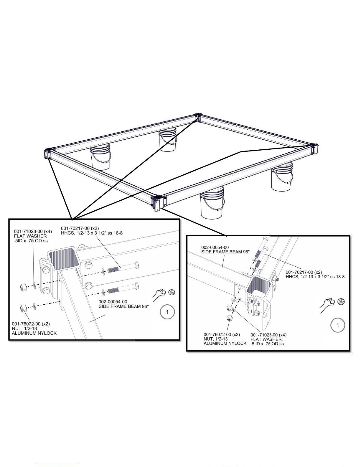
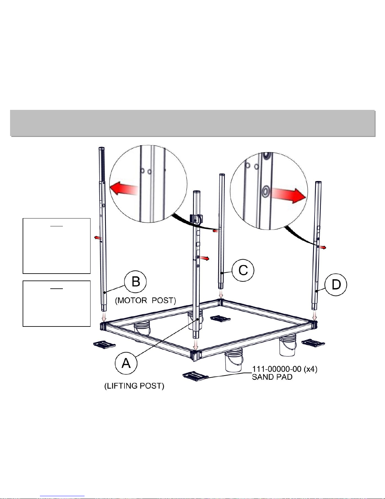
Assembly for Step 1
1-A
1-B
1-C
A
B
C
D
NOTE
(2) ½” Nylock Nuts
and (2) ½” Washers
ARE NOT used for
(2) ½” x 4” Bolts on
corners A and D
until Step 6-D.
A
B 1-D
A
C
1-E
D
FRONT/REAR
FRONT/REAR
IMPORTANT NOTE:
FRAME BEAMS MUST
BE IN THIS
ORIENTATION
BEFORE CONTINUING.
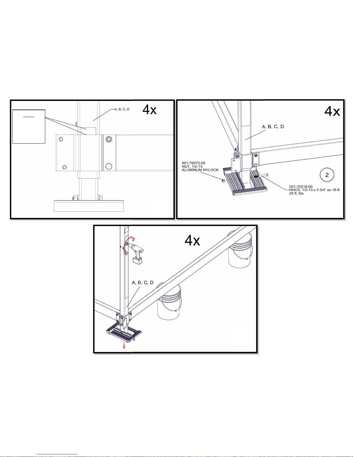
Contents for Step 2
(4) 1/2” Alum. Nylock
Nuts
(4) 1/2 x 3 3/4” SS Bolts Torque to 25 ft. lbs.
Assembly of Step 2
NOTE
CARRIDGE BOLT
HEADS MUST FACE
INSIDE OF LIFT.
NUTS MUST FACE
OUTSIDE OF LIFT.
NOTE
WATER DEPTH
STICKERS MUST FACE
OUT ON FRONT AND
REAR OF LIFT.
NOTE
BUTT
CLAMP UP
TO CORNER
POST TAB
2-A
2-C
2-B
NOTE
THIS TORQUE SPECIFICATION APPLIES TO THE 3” BOLT
(ABOVE 4” BOLT) BOLTS ON POST A AND POST D ONLY.
2-D 2-E
2-F 2-G
 Loading...