

Page 1
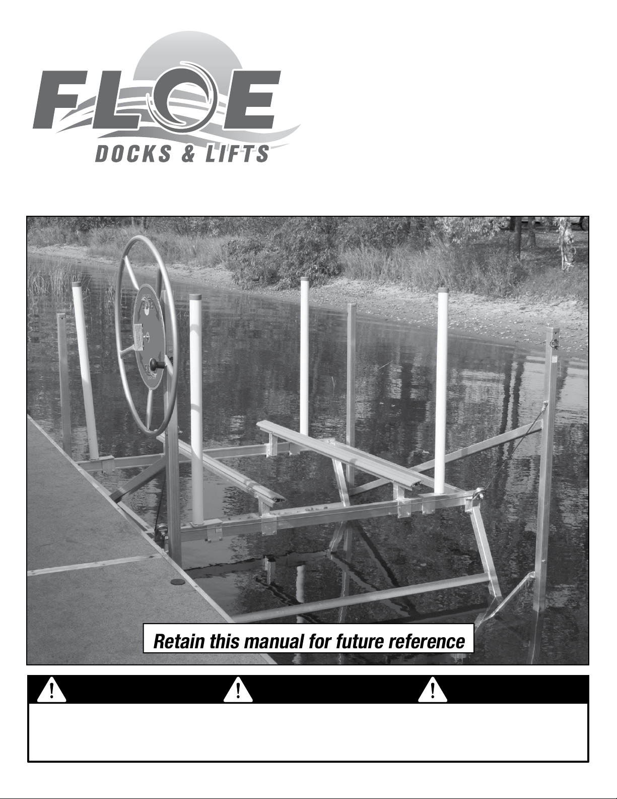
Retain this manual for future reference
OWNER’S MANUAL
P 1200, PWC 1300, P 1600
Pivot Lift Systems
ATTENTION ATTENTION ATTENTION
Read and follow all safety rules and operating instructions
carefully before attempting to install or operate lift system.
Visit our website at www.oeintl.com
1
Page 2

Congratulations on the purchase of your new FLOE Lift!
Like you, I enjoy many kinds of waterfront activities, and I know that
to have fun I need to keep my boat secure, protected, and accessible.
Through my years of experience, I’ve learned how boat lifts should not
only protect your watercraft investment, but also be convenient and easy to use
- and I have developed them accordingly.
The fact that you purchased a FLOE boat lift tells me that you research a product thoroughly.
You will nd a FLOE boat lift has many innovative features that will ensure years of dependable
service, satisfaction, and enjoyment.
Because your FLOE boat lift is engineered to lift and support a tremendous amount of weight,
it is critical that you operate it safely. Anyone who operates this lift must read the entire owner’s
manual before operating the lift to make sure they are able to operate it properly and enjoy all of
its features to the fullest. See you on the water!
Wayne Floe , CEO - FLOE International
CONTENTS
Important Safety Information .......................... 3
Important Safeguards .................................. 3-4
Certicate of Boat Lift Pre-Delivery ................ 5
Boat Lift Capacities......................................... 6
Boat Lift Dimensional Specications ...........7-9
Manual Winch ............................................... 10
Full Length Bunk Set Up............................... 11
Vertical Guide-In Selection & Adjustment ..........11
Leveling the Lift/Leg Adjustment ....................... 12
Boat Lift Installation & Removal Options .......... 12
Boat Lift Wheel Kits .........................................12
Inspections & Maintenance .............................13
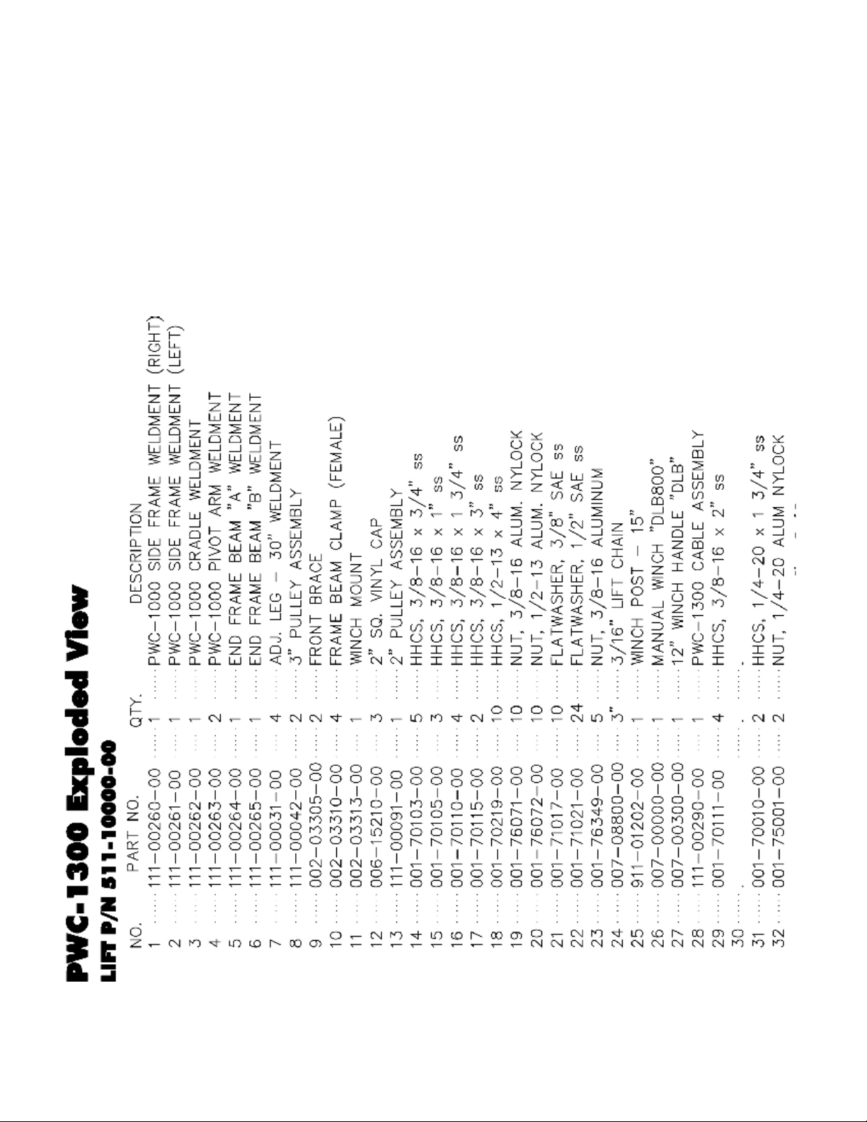
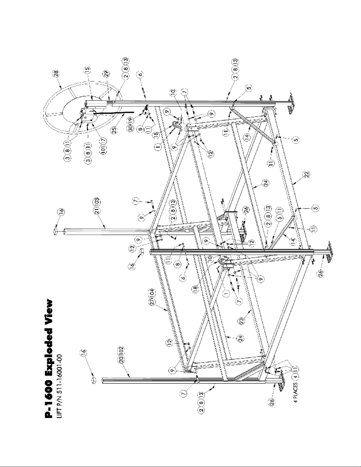
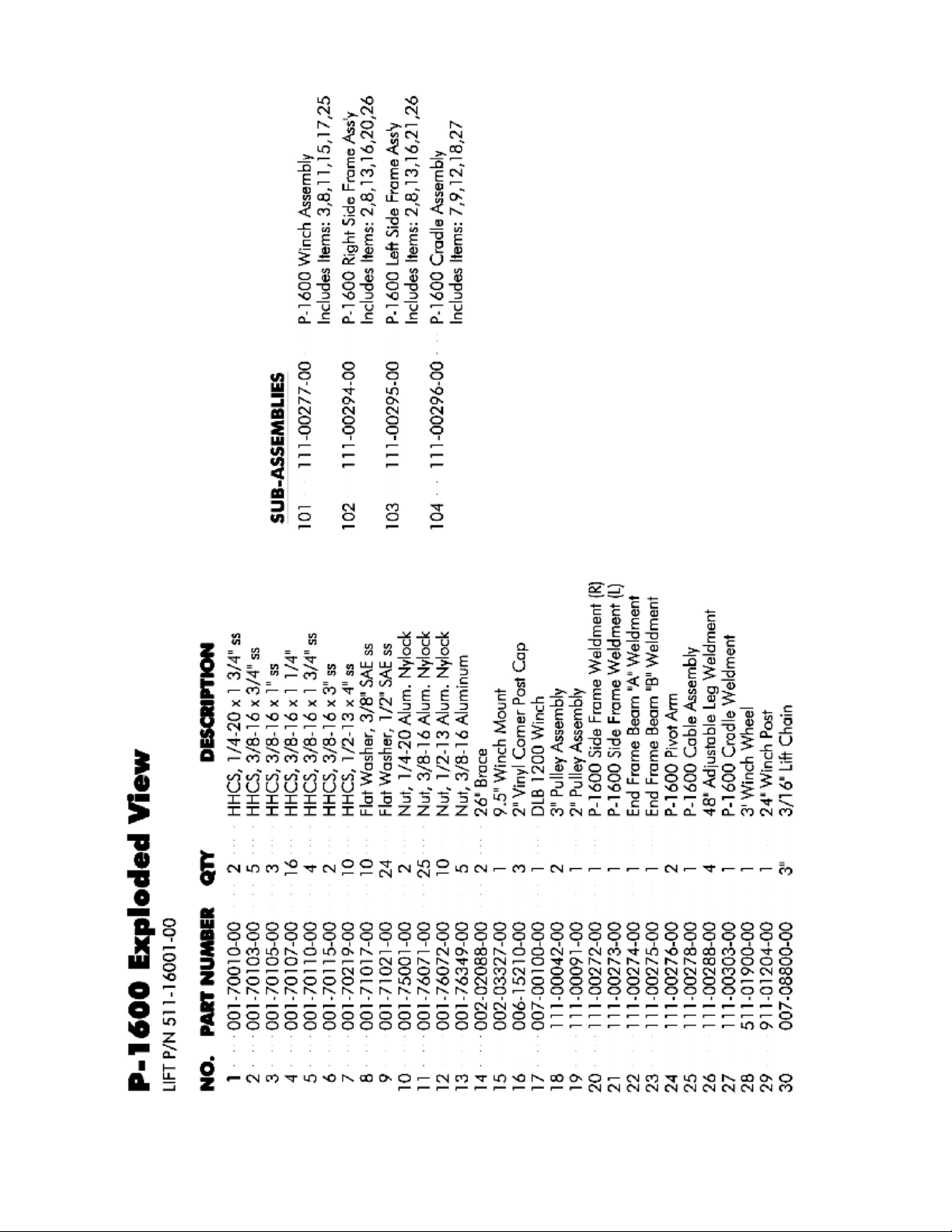
Boat Lift Exploded Views & Parts Lists ...... 14-19
Warranty ....................................................20-21
Warranty Registration .....................................22
2
Please retain this manual for future reference
Page 3
IMPORTANT SAFETY INFORMATION
Your safety and the safety of others is very
important. We have provided many important
safety messages in this manual and on your lift
system. Always read and obey all safety messages.
If you do not understand any of these instructions,
please ask your dealer.
DANGER
You will be killed or seriously injured if
you don’t follow instructions.
CAUTION
This is the safety alert symbol. This symbol alerts you to
hazards that can cause serious injury or
potential death to you and others, plus
damage to the lift system. All safety
messages will be preceded by the safety
alert symbol and the word “DANGER”,
“CAUTION” or “WARNING.”
All safety messages will identify the hazard and tell you how to reduce the chance of injury.
WARNING
IMPORTANT SAFEGUARDS
Read and follow all safety rules and
operating instructions carefully before
attempting to install dock system.
DANGER
You can be killed or seriously injured if
you don’t follow instructions.
WARNING
Failure to take appropriate action could
result in mechanical failure, product
damage and/or cause serious injury or
potential death.
CAUTION
Never allow anyone under this lift system,
especially while it is being operated, or it is
supporting the weight of a watercraft.
Stay clear of boat lift when someone if entering or
exiting the lift with a boat. Never try to assist the
boat’s direction while it is in motion (either from
inside or outside the boat).
Never work on or make adjustments to boat, boat
lift, or boat lift accessories while the lift is supporting
the weight of the boat.
This manual includes the latest information at the
time it was printed. We reserve the right to make
changes in the product after that time without
notice. Keep this manual so it will be available to
who ever is using this product.
While operating the lift, keep all body parts, long
hair, loose clothing, and jewelry away from all
moving parts, including (but not limited to) the
drive-train mechanism, cables, pulleys, and lift
platform.
Be sure the lift cradle is completely lowered
before any adjustments or repairs are made to
the winch.
Always keep all people clear of the boat lift support structure and lifting cradle. Never swim
or play near a boat lift, even if it’s not being
operated.
Make sure the boat lift is completely clear of
people or other obstructions prior to operating.
Do not operate a boat lift with people inside the
boat.
Never operate a boat lift with protective cover
removed from drive train system.
3
Page 4

If the boat lift system is not assembled, installed, or operated properly, mechanical failure,
as well as serious injury or death, could result. See to it that all users understand
that this lift system is a piece of heavy equipment that requires the use of good
judgement and the knowledge of its dangers and limitations.
WARNING
Lift must be assembled and installed
properly or mechanical failure and possible
injury may occur.
Never overload a boat lift. See capacities/
specications for important information
regarding the boat’s actual weight and boat
lift capacity limitations.
Never operate a boat lift that is not level.
Under normal conditions a boat lift
operates under extreme force. When the
lift is not level, these forces are greatly
multiplied and bodily injury or damage to
the lift can result.
Perform all inspections and maintenance on
a regular basis. Replace any worn parts immediately to avoid potential lift failure. Ensure
all pulleys are operating properly and that all
cables and their attach points are secure
and free of excessive wear and fraying. See
Inspections & Maintenance section for all
important details.
FLOE lift systems have not been tested in
brackish or salt water conditions. Lift failures
due to installations in brackish or salt water
locations will not be covered by FLOE’s
warranty. FLOE will not be responsible for
incidental or consequential damages
resulting from these installations.
Never install the lift system in a body of
water whereas either the rising water or
wave action will not always ow under the
main lift beam. For example, do not install
lift in bodies of water with signicant water
uctuation or large water bodies that have
excessive wave action.
Bodily injury or damage to lift system
may result if installation or removal of this
lift is attempted without rst reading and
understanding the installation and removal
section of this manual.
This manual is intended to serve as an owner’s use and maintenance guide for a lift that has been
properly assembled by a qualied, trained professional. Detailed assembly instructions
are packaged with the lift systems.
4
Page 5

All dealers should have reviewed the checklist below with retail customers upon
purchase of a boat lift. If they did not cover this, retail customers must review
thoroughly and understand the statements below.
Certicate of
Boat Lift Pre-Delivery
Date of Purchase ______/______/______ Boat Lift Model ______________________________________
Customer Delivery: Each item must be initialed by the selling dealer upon sale.
______ I understand that the boat lift must be properly assembled and must be tested prior to use with a boat.
______ I understand that a serious injury or death could occur if a boat lift is overloaded, not correctly assembled,
installed, maintained or not used properly.
______ I was given an owner’s manual and I promise to read and understand it before using the boat lift.
______ I understand that it is my responsibility to get clarication on anything in the owner’s manual that I don’t fullly
understand before using the lift system.
______ I understand that I must educate all persons who will be around or using my boat lift as to how to do so safely.
______ I understand that people must stay clear of the boat lift when it is supporting the weight of the boat. No one
should ever swim under it, be on it, in the boat, or in any position that could cause harm to them if the lift
were to suddenly drop.
______ I understand safe operation of the lift requires people to stay clear of moving parts and pinch points.
______ I understand that a boat lift should never be overloaded under any circumstance. A boats published dry
weight is usually substantially lower than its actual loaded weight. Your boat should be weighed with fuel,
water, batteries and contents in order to know its actual weight.
______ I understand the total capacity of the boat lift is equal to the combination load limit of the two main end lift
beams. For instance, a lift with a 5,000 pound capacity has a load limit of 2,500 per lift end beam.
______ I understand that a 5,000 pound total boat weight could easily over-load one of the main lift beams on a
5,000 pound capacity lift. For instance, if the boat was positioned so that one main lift beam supported 3,000
pounds and the other only supported 2,000 pounds, the lift would be over-loaded. For this reason, FLOE
recommends that your total loaded boat weight doesn’t exceed 85% of the lifts rated capacity and that you
locate and place the boat’s center of gravity (balance point) in the center of the two lift beams.
______ I understand that the boat lift needs to be installed level and must be kept level while it is in use. A lift that
isn’t level will have a reduced lifting capacity of 5% per 1” of being out of level.
______ I understand that I need to pull the drain plug on my boat if it is subject to water accumulation as this could
easily overload the boat lift.
______ I understand that I should never lift my boat if it has been swamped or has any signicant additional water
weight in it that will overload the boat lift’s capacity.
______ I understand that if my lift is equipped with a canopy it must be properly secured or it could blow over and
cause damage not covered under warranty.
______ I understand that I must discontinue using the lift immediately and contact my FLOE dealer if any unusual
sounds or functionality are present.
______ I understand I must follow all inspection and maintenance procedures as outlined in my owner’s manual.
Selling Dealership Name_________________________________________________________________________
Selling Dealership Signature_______________________________________________________________________
Print Name
Customer Signature_____________________________________________________________________________
Print Name
5
Page 6

LIFT DIMENSIONAL SPECIFICATIONS - P 1200
LIFT CAPACITIES
WARNING
It’s recommended that the total loaded weight of
the water craft doesn’t exceed 85% of the total
lift capacity. The total capacity of a lift is the
combined capacity of each of the boat lifts two
main lifting beams.
Never exceed the lift’s rated capacity. Doing
so could cause structural/mechanical failure
and serious injury or death.
Specications and models may change without notice
due to continuous improvements to our products
LIFT DIMENSIONAL SPECIFICATIONS - P 1200, PWC 1300, P 1600
MODEL/ WINCH BUNKS BED INSIDE OUTSIDE FRAME
CAPACITY OPTIONS TRAVEL WIDTH WIDTH LENGTH
P-1200-lb. Crank Wheel Full-length 28” 70” 74” 91”
PWC-1300-lb Crank Wheel Full-length 28” 58.5” 62.5” 61”
(standard)
P-1600-lb Crank Wheel 32” 84” 88” 91”
MODEL/ LEVELING TRAVEL CANOPY GUIDE-IN MAX INSIDE WEIGHT
CAPACITY LEG WITH OPTION OPTIONS WIDTH WITH (LBS.)
TRAVEL EXTENSIONS GUIDE-INS
P-1200-lb. 0-24” N/A N/A Sgl-Vert 63” 175
PWC-1300-lb 0-24” N/A N/A Sgl-Vert 48” 130
P-1600-lb 0-24” N/A N/A Sgl-Vert 75.5” 220
6
Page 7
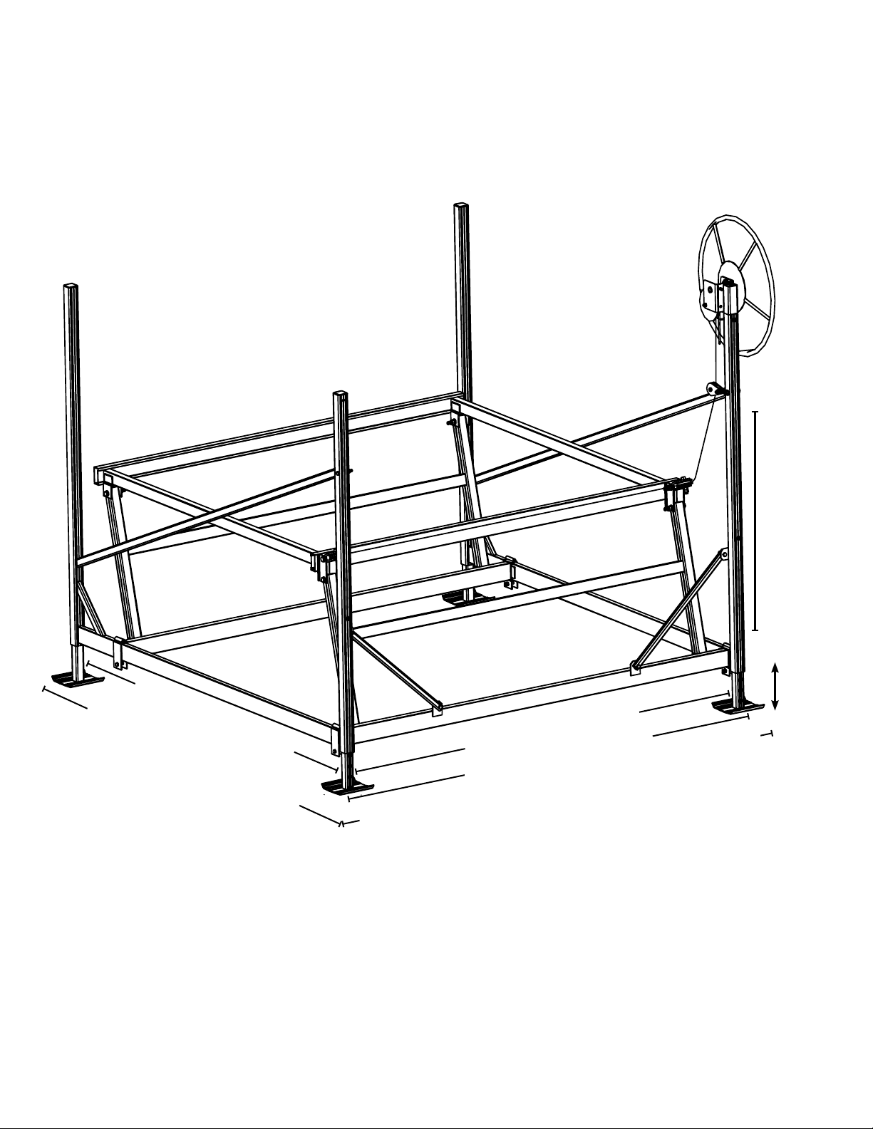
LIFT DIMENSIONAL SPECIFICATIONS - P1200, PWC 1300, P1600
LIFT DIMENSIONAL SPECIFICATIONS - P 1200
8 9 ”
72
1
8
“
P1200
Bed
Travel
28”
Inside frame length: 87”
Outside edge of sandpad
to outside edge of sandpad: 96”
Leg
Travel
24”
Inside frame width: 70”
Outside frame width: 74”
Outside edge of sandpad to outside edge of sandpad: 79”
7
Page 8
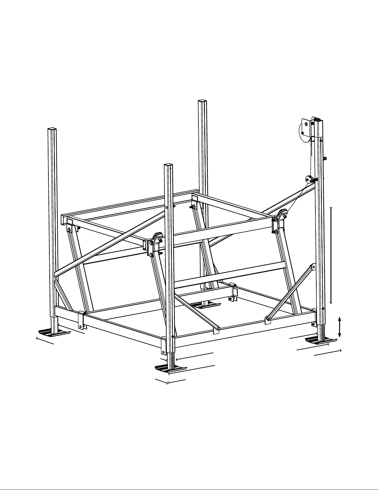
PWC1300
Bed
Travel
28”
Leg
Travel
24”
Inside frame length: 57”
Outside edge of sandpad
to outside edge of sandpad: 65
¾
”
8
Inside frame width: 58
Outside frame width: 62
Outside edge of sandpad
to outside edge of sandpad: 67
”
½
”
½
”
½
Page 9
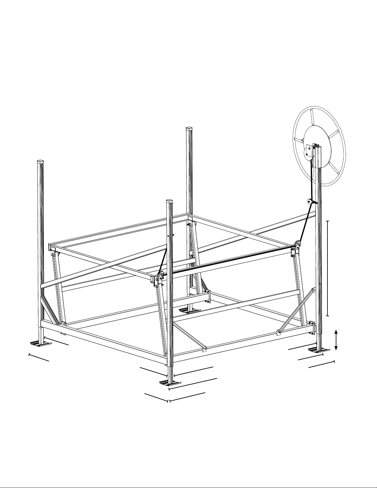
P1600
Bed
Travel
32”
Inside frame length: 87”
Outside edge of sandpad
to outside edge of sandpad: 96”
Inside frame width: 84”
Outside frame width: 88”
Outside edge of sandpad
to outside edge of sandpad: 93”
Leg
Travel
24”
9
Page 10
MANUAL WINCH CRANK WHEEL
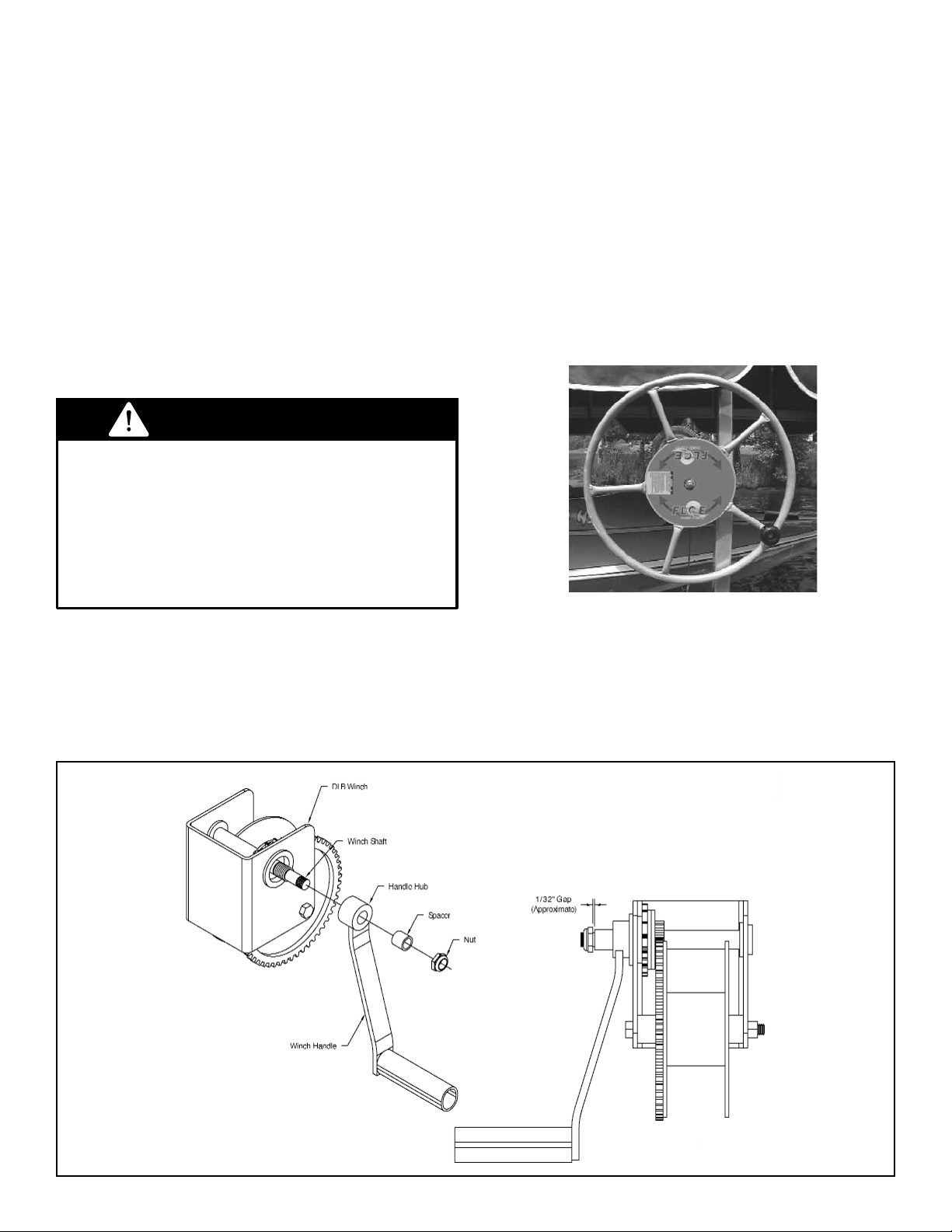
FLOE includes a winch crank handle with each pivot lift or
the customer can upgrade to a crank whee. The crank
wheel with a speed knob attachment makes using the
manual winch easy. (Fig. 21) The P1200 and P1300 uses
a 24” wheel while the PWC1600 uses a 36” wheel. These
large-diameter wheels dramatically reduce the amount of
effort that a regular crank handle would require to raise or
lower the boat. The speed knob is easy to grasp and
allows you to turn the wheel with one hand.
Fig. 21 Crank Wheel
With Speed Knob
WARNING
When raising lift a clicking sound should be heard indicat-
ing proper rotation and brake function. If no sound is
heard a fast uncontrollable spin-down could occur.
Attempting to stop the crank wheel during an uncontrol-
lable spin-down could result in severe injury.
MANUAL WINCH
MANUAL WINCH CRANK WHEEL
The brake style winch operates by maintaining
pressure on the brake pad any time the winch is
being cranked to raise the cradle lift beams. As
the “dog” catches each cog of the sprocket, you
will hear a clicking sound. This indicates that the
brake is working properly, and that the drum is
turning while the brake prevents the cable from
unwinding uncontrollably. When you “back the
wheel off” by turning it in a counterclockwise direction, the pressure on the brake is reduced,
allowing the smooth lowering of the cradle lift
beams and boat.
WARNING
When raising lift a clicking sound should
be heard indicating proper rotation and
brake function. If no sound is heard, a fast
uncontrollable spin-down could occur. The
boat or lift is unlikely to be damaged during
a spin-down, but attempting to stop the crank
wheel could result in severe injury.
ASSEMBLY INSTRUCTIONS
FLOE includes a winch crank handle with each
pivot lift or the customer can upgrade to a crank
wheel. The crank wheel with a speed knob
attachment makes using the manual winch easy.
(Fig. 1) The P1200 and P1300 uses a 24” wheel
while the PWC1600 uses a 36” wheel. These
large-diameter wheels dramatically reduce the
amount of effort that a regular crank handle would
require to raise or lower the boat. The speed knob
is easy to grasp and allows you to turn the wheel
with one hand.
Fig. 1: Crank Wheel With Speed Knob
Attach the winch handle (or wheel) as shown. Slide the handle over the shaft and thread clockwise until
the hub is seated into the winch. Slide the spacer over the shaft and fasten the nut. Do not tighten nut
to spacer, leave approximately 1/32” space to allow the winch brake to release properly.
10
Page 11
BUNK SET UP
PRO-PARK™ VERTICAL GUIDES
It is important that you follow two important rules
when installing the bunk system. 1. If the lift is in
shallow water, make sure that the vertical support tubes are either set or cut short enough that
they do not hit the lake bottom and prevent the
main cradle lift beams from lowering completely.
2. Always adjust the height of the bunks so that
the boat’s hull does not touch the main cradle lift
beams.
IMPORTANT NOTE
THE LIFT SHOULD BE INSTALLED WITH 6” OF WATER ABOVE
THE TOP OF THE BUNKS WHILE THE LIFT IS IN LOWERED
POSITION. THIS WILL PROVIDE ADEQUATE CLEARANCE FOR
LAUNCHING AND DOCKING OF YOUR WATERCRAFT AND WILL
ALSO HELP PREVENT FLOAT-OFF IN THE RAISED POSITION
DURING HIGH WAVE CONDITIONS.
FULL-LENGTH BUNKS
Full length bunks are excellent for stabilizing and
providing superior support for boats. The bunks
will be spread out toward the edges of the hull
to better distribute the watercraft’s weight on the
rear cradle lift beam. Detailed instructions for
setting up and adjusting the bunks are included
with the bunk system. See Fig. 2.
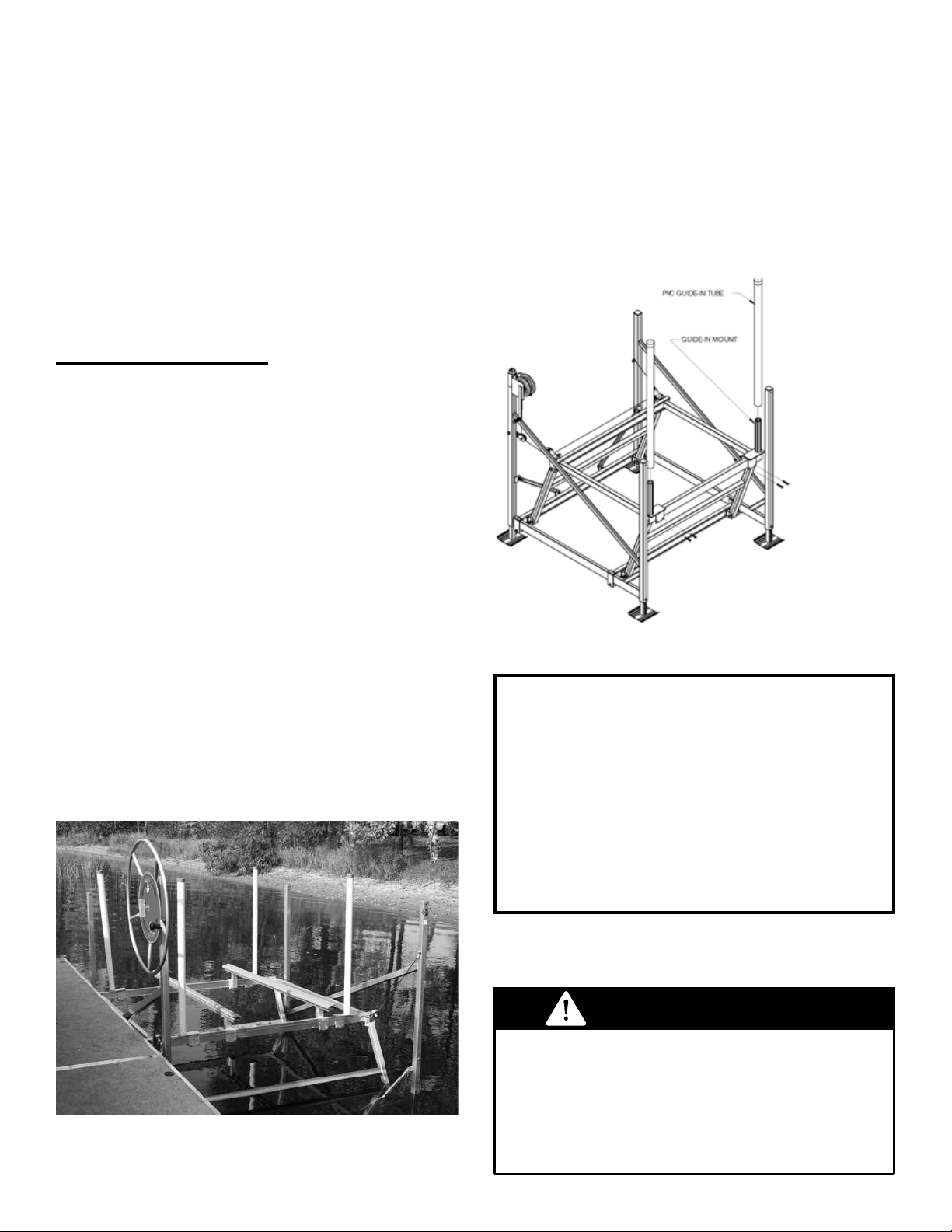
The FLOE vertical guide-in system is designed
to guide the watercraft by its rub rail so it never
touches or mars the hull. It has an innite
adjustment range limited only by the width of the
lift, to allow for a perfect t. These are available
in pairs of single guides for pivot lifts. See Fig. 3.
Fig. 3: Shown with one
single pair of guide ins.
ADJUSTING THE GUIDES
1. With the guides on the lift, but not tightened, oat
the watercraft over the lift into its proper position.
2. Raise the lift platform until it holds the watercraft
centered in place.
3. Slide the guides up to the watercraft’s rub rail.
4. Remove the watercraft.
5. Raise the lift platform and tighten the guides to
35 ft. lbs.
Fig. 2
WARNING
Watercraft must oat freely over the bunks
before lifting. The weight of the craft should
never be on the lift when it is in it’s lowest
position. Failure to follow this procedure may
result in severe damage to your lift and/or
watercraft and will void your warranty.
11
Page 12
LEVELING THE LIFT/LEG
ADJUSTMENT
To level the lift, loosen the bolt from the leveling
legs. Pull the inner leg out until it is at the proper
depth. Tighten the bolt. Repeat for all 4 legs. For
proper operation of the lift, it is important that the
lift is level.
BOAT LIFT INSTALLATION
& REMOVAL OPTIONS
If the lift is in a climate where the lakes freeze
during the winter months, it may need to be
installed and removed from the lake on a seasonal
basis. FLOE has wheel kits designed to make
this easier.
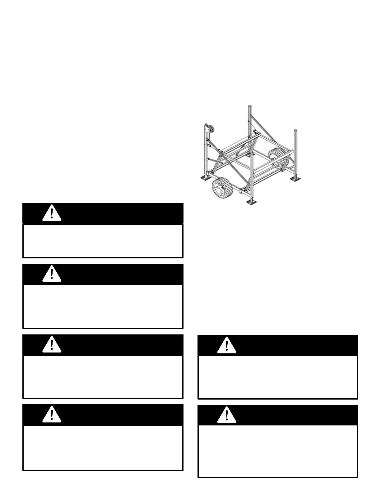
BOAT LIFT WHEEL KITS
Boat lift wheel kits are available for the P1200 &
P1300 lifts. Attach wheel kits to lift frame according to wheel kit assembly instructions included
with your boat lift wheel kit. To install the lift with
the optional wheel kits in place:
1. Raise the leveling legs so they are fully retracted.
Fig. 4: Boat Lift
Wheel Kit (one pair)
DANGER
Never work on or make adjustments to boat,
boat lift, or boat lift accessories while the lift is
supporting the weight of the boat.
WARNING
Keep all body parts and clothing away from
cables and moving parts. Do not attempt to
stop the wheel if an uncontrollable spin-down
should occur.
DANGER
Stay clear of boat lift when someone is
entering or exiting the lift with a boat. Never
try to assist the boat’s direction while it is in
motion (either from inside or outside the boat).
To install the lift with the optional wheel kits in
place:
1. Before transporting the lift, make sure the
cradle is raised at least two feet, as shown in
Fig. 4. This will prevent the wheels from hitting
the side cradle beams, which would keep the
wheels from turning freely.
2. Once the weight of the lift is supported by the
wheels, roll the lift into position by hand, or pull it
with a boat using a cable harness.
3. Once the lift is in place, lower the leveling
legs until the lift is level and the wheels are off
the bottom.
WARNING
The wheels must not touch the lake bottom
once the lift has been installed. The weight
of the boat and lift must be supported by the
sand pads only.
DANGER
The operator should always watch the lift bed
and stop before exceeding the stop limit and
“Stop Here” decals. Failure to do so can result
in serious bodily injury.
12
WARNING
Never tie a rope, chain or cable to the center
of a lift’s frame beam. This can bend or break
the beam. Always use a “Y” cable harness
set-up to more equally distribute the pressure
on the frame.
Page 13
INSPECTIONS & MAINTENANCE
Main Cradle Lift Beam
Side Cradle
Lift Beam
Circles indicate pulley
locations
Note: Pulley Block (comes with winch
on V2002, V3400 & V4200)
Fig. 70 Sheave Locations (Total of Seven)
There is one sheave that comes with the winch in a dou-
ble-pull system. In the lift itself there is one sheave at each
end of the two side cradle lift beams and one at each end
of the front cradle lift beam.
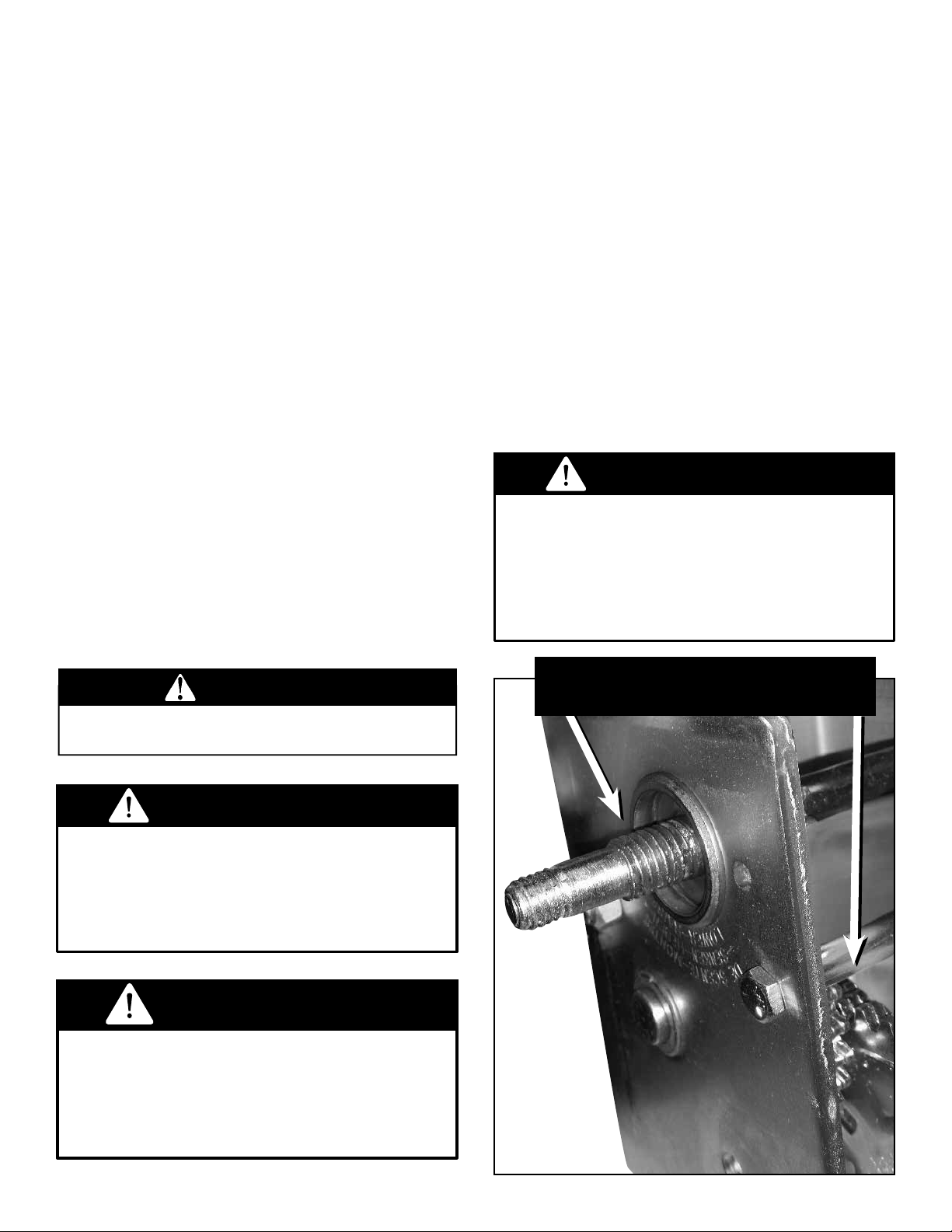
Always remove the boat and lower the lift bed completely before attempting any maintenance or repairs.
WARNING
WINCH MAINTENANCE
• Check all structural fasteners annually to ensure
that they are tight.
• Inspect all cables at least annually. Any frayed,
deteriorating or visibly stressed cables must be
replaced before the lift is used.
• If the lift receives wind damage or is moved or
blown over by the wind a full inspection (preferably by a trained FLOE dealer or other knowledgeable professional) must be completed before the
lift is used.
• Check all pulleys (sheaves) annually to make
sure they are turning free and true. Ensure that
the cables are running properly in the grooves or
channels of the pulleys. Check the bushings for
any signs of wear. If there is too much vertical
play at the top and bottom of a pulley on its axis
(more than an 1/8”) replace the bushing and if
necessary the sheave itself.
• Visually inspect lift frame annually for cracks or
damage. Replace any cracked or damaged parts
before using lift.
In order to ensure maximum performance, a
periodic inspection for any necessary preventative maintenence should be made. Check at
least once annually and more frequently when
the winch is exposed to an environment which is
particularily dirty or wet. For continued smooth
performance and increased life, occasionally
grease gears, reel shaft, and handle threads (see
Fig. 5). An occasional drop of oil on the drive
shaft bearings is also recommended.
Keep winch in good working order. Damaged or
severely worn parts create unnecessary dangers
and could result in personal injury or property
damage.
WARNING
Loose fasteners can cause instability in the
lift frame resulting in premature wear to the
lift structure and create a structurally unsafe
boat lift. Damage due to loose fasteners or
improper assembly and/or maintenance will
void warranty.
GREASE ANNUALLY
WARNING
Do not use a boat lift with cables that show
any abnormalities. If a cable breaks under
pressure, the boat will drop suddenly causing
potential damage to the boat, the boat lift, and
can cause serious injury or death.
WARNING
Pulleys with worn bushings can cause damage
to the beam where they are located and
cause excessive friction while the lift is being
operated. This can also severely damage other
components such as the drive train and cables.
Fig. 5
13
Page 14
12
14
Page 15
15
Page 16
14
16
Page 17
15
17
Page 18
16
18
Page 19
17
19
Page 20
FLOE INTERNATIONAL, INC.
BOAT LIFT SYSTEM 15 YEAR LIMITED WARRANTY
FLOE INTERNATIONAL, INC. warrants, to the original purchaser, the FLOE boat lift system to be free from original defects in materials and workmanship under
conditions and loads for which designed as outlined in the owner’s manual from date of purchase as follows:
NEW WARRANTY GUIDELINES EFFECTIVE SEPTEMBER 1, 2004
TWO-YEAR PARTS AND LABOR WARRANTY
FLOE International, Inc. will repair or replace, at their option, any portion of the lift system which fails as a result of a defect in material or workmanship
during the rst two years after the date of purchase. FLOE INTERNATIONAL, INC. reserves the right to inspect and perform repairs at its main facility (F.O.B.)
McGregor, Minnesota. Any failure due to product assembly by a FLOE dealer or consumer is not covered by this warranty. This full two-year warranty includes
parts and labor on the boat lift system and accessories including the following: (warranty does not cover paint, plated surfaces, or nish).
Aluminum structure, guide-ins, bunk systems, motor stops, crank wheels, canopy frames, canopy fabrics (excluding color fading or matching separate canopy
fabrics), solar chargers, wheel kits, adjustable leveling legs, VSD drive train and electrical components, DC winches, corded and wireless remotes, cables, pulleys
and installation and removal accessories.
Labor charges and mileage are covered within 40 miles from FLOE or the authorized FLOE dealership performing the repairs. Additional mileage/travel
charges will apply if travel over 40 miles is required. If this charge applies, it is determined by the repairing dealer and must be paid by the customer to the
dealer performing the repairs. Warranty does not cover damage, including broken welds, caused by improper installation or removal, or any damage of any
sort caused by the use of power equipment.
EXTENDED PARTS WARRANTY
In addition to this two-year parts and labor warranty, additional warranty coverage applies to specic parts of the lift and accessories. All warranty coverage
beyond two years is for parts only. Labor and mileage costs for any warranty claim are not covered past two years.
ALUMINUM STRUCTURE — 15-YEAR LIMITED WARRANTY
Defects in material and workmanship of structural components of the lift frame are covered fully for 10 years from the date of purchase. FLOE will provide
replacement parts, on a non pro-rated basis, for ten years for these items if they are found to be defective. The lift frame consists of the aluminum framework
making up the boat lift structure, including the lift cradle which is the portion of the lift frame that moves up and down as the boat lift is operated. It does
not include the bunks or other accessories that are listed below. After this 10-year parts warranty, an additional ve-year pro-rated warranty covers these
components as shown below.
Year After Purchase Consumer Portion of Current Retail Price Year After Purchase Consumer Portion of Current Retail Price
11 40% 14 70%
12 50% 15 90%
13 60%
ACCESSORIES AND COMPONENTS — 10-YEAR LIMITED WARRANTY
Defects in material and workmanship of certain accessories and components of FLOE lift systems are covered under a 10-year pro-rated warranty. This pro-rated
parts warranty begins after the two year parts and labor warranty. Items covered in this 10-year pro-rated warranty include lift bunks (excluding vinyl cover
ing), guide-ins, motor stops and the canopy frame.
The pro-rated schedule on these items is as follows:
Year After Purchase Consumer Portion of Current Retail Price Year After Purchase Consumer Portion of Current Retail Price
3 20% 7 60%
4 30% 8 70%
5 40% 9 80%
6 50% 10 90%
-
20
Boat Lift warranty page 1 of 2
Page 21
ACCESSORIES AND COMPONENTS FIVE-YEAR LIMITED WARRANTY
Defects in material and workmanship of certain accessories and components of FLOE lift systems are covered under a ve-year pro-rated warranty. This
pro-rated parts warranty begins after the two-year parts and labor warranty. Items covered in this ve-year pro-rated warranty include canopy fabrics (exclud
ing color fading or matching separate canopy fabrics), manual winches, cables, adjustable leveling legs, drive trains, DC winches, wheel kits, corded remotes,
limit switches, wireless systems and solar panels.
The pro-rated schedule of these items is as follows:
Year After Purchase Consumer Portion of Current Retail Price
3 50%
4 55%
5 60%
On these items, it is important to note the following exceptions:
• Warranty is void on all winches and drive-trains if they are submersed into water (including the initial two-year warranty).
• Warranty is void on ball-screws and ball nuts, winch gears, adjustable leveling legs, or any other item that failed due to improper maintenance or
lubrication as noted in owner’s manual.
All canopies are date coded. Date tag must be attached to canopy or warranty is void. Canopy fabric warranty does not cover valance or trim, as delamination
may occur in high wind areas. If returning canopy for warranty repair, canopy must be cleaned prior to returning or a $100 cleaning charge will be applied.
This warranty covers only the cost for replacement of materials due to defects in materials or workmanship, and represents the only warranty authorized by us.
In order to receive performance under this warranty, all warranty repairs must be authorized in advance by FLOE INTERNATIONAL, INC.
-
ADDITIONAL WARRANTY INFORMATION INCLUDING EXCLUSIONS AND OWNER’S RIGHTS
FLOE International, Inc. (manufacturer) will not be responsible for any costs incurred for, or as the result of, unauthorized repairs or improper assembly. Unauthorized repairs may void the warranty on the repaired part(s). This warranty does not cover damage, malfunction or faulty operation resulting from overload,
misuse, wind, storms, ice, salt/brackish water applications, negligence, being hit by watercraft of any kind and any other ‘Act of God’. Manufacturer’s war
ranty coverage extends to private use only and is not applicable to commercial or rental use. Manufacturer is not responsible for damage or in-operability due
to repairs made by unauthorized service personnel. Parts purchased by the manufacturer are warranted by the company that manufactured the part under the
warranty schedule associated with the part in question. Manufacturer’s warranty is extended to the original owner only and is non-transferable. Manufacturer
reserves the right, at its own discretion, to inspect and perform repairs at its main facility in McGregor, MN. The customer is responsible for any and all freight
charges incurred to transport the product to and from McGregor, MN, with the exception of claims covered by the manufacturer’s two-year parts and labor
warranty which has provisions for service work to be completed up to 40 (forty) miles away from a FLOE dealership. Manufacturer’s warranty claim process,
specications and pro-rate scheduling may change without notice and/or obligation.
-
COMPLETING AND SUBMITTING YOUR WARRANTY CLAIM
To receive performance under this warranty, contact your authorized FLOE dealer. Be prepared to provide the following information so that the dealer can
complete a warranty claim form: receipt and date of purchase; your name, address and telephone numbers; the serial or vehicle identication numbers; and a
detailed description of the problem.
THERE ARE NO OTHER EXPRESSED OR IMPLIED WARRANTIES
Our obligations under this warranty are limited to repair or replacement at our discretion and
FLOE SHALL NOT BE LIABLE FOR INCIDENTAL OR CONSEQUENTIAL DAMAGES OF ANY KIND.
This Warranty gives you specic legal rights and you may have other rights which may vary from state to state.
Boat Lift warranty page 2 of 2
21
Page 22

Be sure to register your FLOE boat lift. Register online
at www.oeintl.com or by mailing your Warranty
registration card to the address below.
FLOE International, Inc.
Warranty Registration Department
48473 State Highway 65
McGregor, MN 55760-9514
WARRANTY REGISTRATION CARD
NOTE: This card must be completed by the FLOE Retail Dealer or the customer and returned to
FLOE INTERNATIONAL, INC. within *15 days of purchase, to validate warranty. Please afx proper
postage before mailing. Please complete all information requested.
*FLOE INTERNATIONAL, INC. is not responsible for lost, stolen or misplaced warranty
registration cards.
NAME: _________________________________________________________________ PHONE: ______ / _______________
ADDRESS: ____________________________________________CITY: __________________ STATE: __________ ZIP: ________
DATE PURCHASED: ________/ ________/ ________ DEALER PURCHASED FROM: _______________________________________
PRODUCT PURCHASED
FLOE TRAILER ................... SIZE: _________ MODEL: __________ VIN#:__________________________________
TRAILER ENCLOSURE ....... SIZE: _________ MODEL: __________________________
BOAT LIFT SYSTEM ...........MODEL: _________________________________________
ROLL-IN DOCK .................. DECKING IS: CEDAR - CARPETED - ALUMINUM
FLOATING DOCK ................DECKING IS: CEDAR - ALUMINUM
NOTE: Please list SIZE for each Dock Component.
SIZE: ______x______ SIZE: ______x______ SIZE: ______x______ SIZE: ______x______
SIZE: ______x______ SIZE: ______x______ SIZE: ______x______ SIZE: ______x______
ACCESSORY: ____________________ ACCESSORY: ____________________
ACCESSORY: ____________________ ACCESSORY: ____________________
IF NOT REGISTERING ONLINE, MAIL IN YOUR ORIGINAL WARRANTY CARD
22
Please check all that apply
OR PHOTOCOPY THE ABOVE CARD.
Page 23
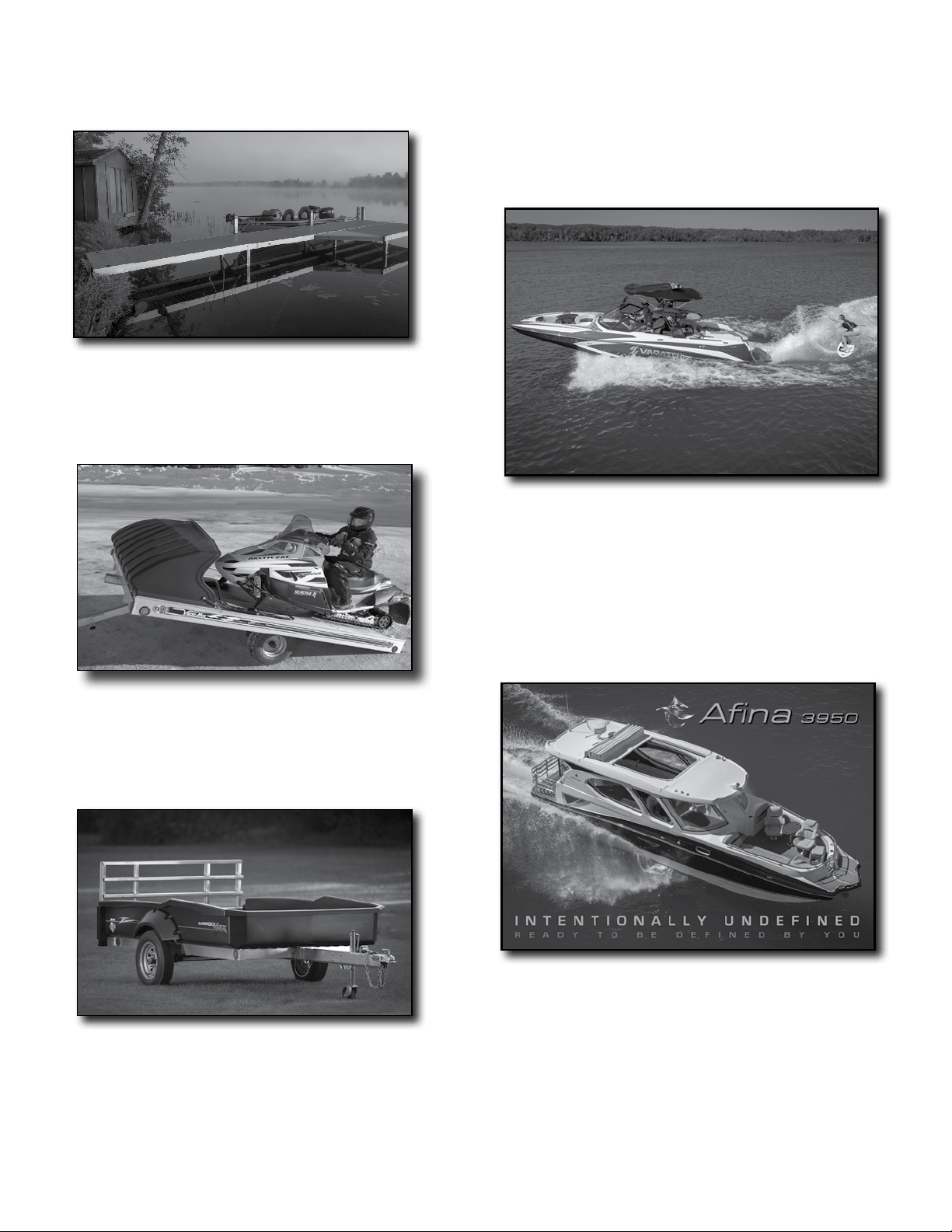
FLOE manufactures an extensive line of other products
MODULAR SECTIONAL DOCKS – FLOE’s Sectional Docks are a great
value and ideal for lake lots with minimal space or hilly terrain where
roll-in systems won’t work. The docks sections break down in
seconds with no tools for easy stacking storage.
Surfing, absolutely! Wake boarding and skiing, you better believe it.
Tubing, of course. A martini cruise at sunset or a quick trip to your favorite
restaurant – whatever you decide to do, the Varatti Z22 delivers. Our
philosophy is, we build the boat, you decide what to do with it. The Varatti
Z22 has no restrictions on fun.
FLOE open and enclosed trailers are available in many styles and sizes
to accommodate your needs. FLOE trailers have an aluminum frame
that resists corrosion and never rusts. Aluminum construction allows
for a light trailer while still offering the strength you need.
The Cargo Max XRT Trailer is a world-class combination of style,
durability and simplicity. The trailer is engineered with a high-
strength extruded aluminum frame and an ultra-rugged high-density
polyethylene trailer body. It can haul and be towed by ATVs, and is
great for yard work, hunting, camping, cabin travel, construction,
rental, shopping and almost any other use imaginable.
The Afina 3950 is the ultimate expression of our challenge to the status quo.
Instead of simply following a checklist, we decided to completely reimagine what
your boat should be. From unique features like power windows and a retractable
roof providing integrated climate control to a hull that planes quickly
coupled with easy maneuverability, this elevates boating into an art form.
23
Page 24

Thank you for purchasing a quality FLOE
boat lift. Understanding the information in this
manual should help you to keep your boat lift
in optimal working condition for many years of
worry-free enjoyment.
Please take the time to record this important
information for future reference:
Model
Number:____________________________
Date of
Purchase:__________________________
NOTE: Not all boat lifts will be identied with
a serial number. It is a good idea to save your
receipt from the dealer.
Your authorized FLOE Dealer:
FLOE INTERNATIONAL, INC.
24
P/N 500-90115-01
48473 STATE HIGHWAY 65 • McGREGOR, MN 55760
www.oeintl.com
All material copyright © 2019 FLOE International, Inc. Unauthorized reproduction is strictly prohibited.
Specications subject to change without notice.
7/19
 Loading...