

Floe 500-95500-00 Owner's Manual

OWNER’S MANUAL
8’
ATV Pro
Tilt Trailer
8’ & 10’
All-Terrain Pro
Utility Trailers
10’ & 12’
Versa-Max
Tilt Trailers
Featuring FLOE’s exclusive Versa-Track System™
Page 1

Congratulations!
Dear Customer,
We appreciate your business and hope you are proud of your new Floe aluminum trailer – a pride that will continue
throughout the years. If you shopped trailers before deciding on the Floe, you probably concluded that our trailer has
numerous features not commonly found on others.
At FLOE INTERNATIONAL, we take great pride in providing the highest quality trailer, with the latest state-of-the-art
features, at an affordable price. Each year we implement improvements to our product lines to ensure that we are on the
“leading edge” and providing the best available trailer.
We are condent your Floe trailer will provide you with years of trouble free trailering, and that if you decide to buy another
trailer, it is because you want another Floe model.
Please take the time to read and understand this owner’s manual before towing your new trailer. The information offered here
will have a direct impact on your safety, the safety of others, and the dependability of your trailer.
Thank you for choosing Floe.
Sincerely,
Wayne Floe
CEO, Floe International
Contents
Important Safety Information .............................................. 3
Reporting Safety Defects ...............................................3
Procedure for Vortex Hub / Spindle ...................................... 4
Adding & Changing Grease .......................................... 4
Removing/Remounting .................................................. 5
Axle Assembly ............................................................... 6
Using Your FLOE Trailer ...................................................... 7
Hitch Selection ............................................................... 7
Hitch Coupler Adjustment..............................................8
Tilt Clamp ......................................................................8
Proper Loading & Unloading ......................................... 9
Securing Ramp ............................................................... 9
Trailer Safety
Securing the Load ...................................................10-12
Trailer Lighting ................................................................... 12
Changing Tires ............................................................. 13
Care & Maintenance .................................................... 13
Tire Safety ...............................................................14-30
Accessory Installation ....................................................32-33
Common Questions and Answers ....................................... 34
Specications Chart ............................................................ 35
Warranty ......................................................................... 36-38
Page 2
Important
Safety Information
READ THIS INFORMATION BEFORE USING TRAILER!
It is the owner’s/operator’s responsibility to
check the following items each time before
towing trailer:
• Wheel bearings are properly tightened and oiled.
• Tires are inated to correct pressure.
• Lug nuts on each wheel are tight.
• Trailer is level with tow vehicle and load is
positioned to apply equal weight to all tires.
• Bed locking system (tilt clamp) is properly
secured.
• Ensure safety chains cross each other and open
end of “S” hook faces the trailer.
• Ensure any cables are secure.
• Trailer coupler is properly adjusted and securely
attached to the hitch ball.
• If equipped, brake system is working properly
and breakaway cable is securely attached.
• Trailer electrical connector is properly connected
and all lights are operating correctly.
- - - - - - - - - - - - - - IMPORTANT- - - - - - - - - - - - - Whether you are using your trailer for
hauling snowmobiles, ATVs or other items,
it is important that you take simple safety
precautions every time you use your trailer.
WARNING
may result in damage to your trailer or vehicle,
and could cause severe or fatal injury to you
or others.
Reporting Safety Defects
If you believe that your trailer has a defect
which could cause a crash or could cause injury
or death, you should immediately inform the
National Highway Trafc Safety Administration
(NHTSA) in addition to notifying FLOE
INTERNATIONAL, INC. at 1-800-336-6337.
• Load is secure. Monitor load at regular intervals
once underway.
• Trailer capacity and tongue weight are not
exceeded.
• The width of the trailer in proportion to your
vehicle. Take mental note if trailer width
exceeds that of your towing vehicle and drive
accordingly.
• No structural damage to trailer exists. Do not use
if damaged.
Page 3
If NHTSA receives similar complaints, it may
open an investigation, and if it nds that a safety
defect exists in a group of vehicles, it may
order a recall and remedy campaign. However,
NHTSA cannot become involved in individual
problems between you, your dealer, or FLOE
INTERNATIONAL, INC.
To contact NHTSA, you may either call the Auto
Safety Hotline toll-free at 1-888-327-4236 (TTY:
1-800-424-9153); go to http://www.safercar.gov; or
write to: NHTSA, US Department of Transportation,
1200 New Jersey SE, Washington, D.C. 20590. You
can also obtain other information about motor vehicle
safety from http://www.safercar.gov.
Procedure for
Vortex Hub
Owners Manual
Old
Out
Out
New
Grease
In
Old
Out
Out
New
Grease
In
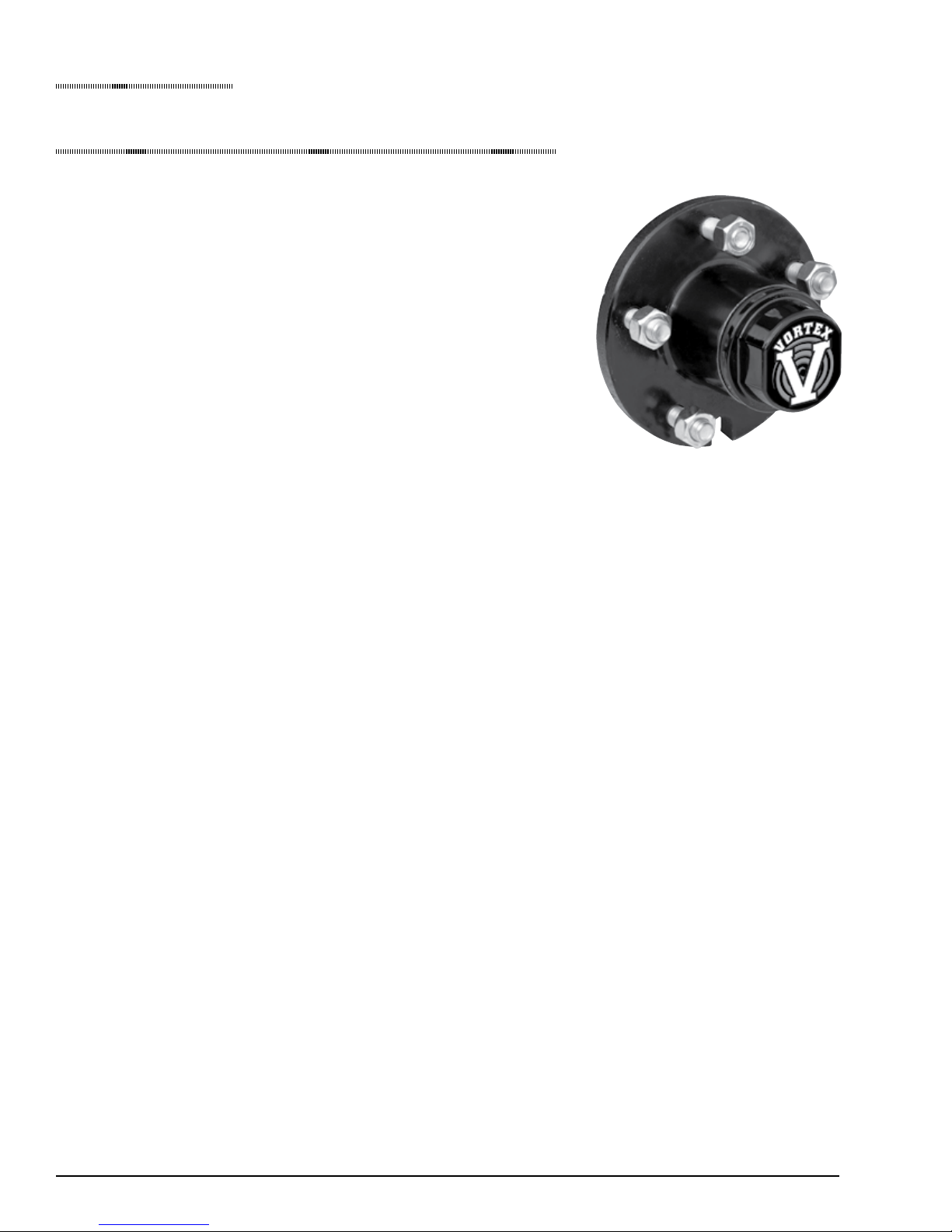
Vortex Hub/Spindle
Simple is best when it comes to Wheel bearing lubrication. Tie Down
has adapted the best features of grease and oil lubrication to develop the
Vortex hub. The Vortex hub bearing lubrication system provides long
term continuous bearing lubrication and ease of service or inspection.
Your trailer is equipped with Vortex hubs/spindles from Tie Down
Engineering. The hubs are pre-grease and assembled at the factory
and should not require any additional adjustments, The Vortex hub
uses tapered roller bearings adjusted to a maximum .006 end play.
The twelve sided castle nut easily maintains this maximum .006 end
play. The conguration requires a minimal amount of end-play that is
factored in at the time of assembly.
Vortex Features:
• Stainless steel wear sleeve on factory assembled spindle/hub units
• Vortex internal through the spindle lubrication system
• Super strong threaded removable grease cap
• Premium grade Lucas Oil Marine grease (100,000 miles)
WHAT MAKES THE VORTEX THE BEST
The rear seal rides on a stainless steel wear sleeve. This provides longer life for the seal as the surface
does not corrode. Corroded or rusted seal surfaces act like sandpaper on the seal causing premature
failure. Vortex lubrication makes changing or adding grease easy with no need to remove the hub. The
threaded grease cap is easy to remove and replace. No more knocking the cap off with a hammer. Lucas
Oil Marine grease is a premium lithium based complex fortied with rust and oxidation inhibitors, high
pressure additives and provides a high degree of moisture resistance and washout properties. These
features allow Tie Down Engineering to offer a 6 year, 100,000 mile limited warranty. See separate
warranty sheet for details.
The Vortex hub/spindle is designed to be a no maintenance hub for 6 years. If you should need to add
grease or remove the hubs for any reason, follow the instructions listed in this owner’s manual.
TO MAINTAIN THE FACTORY WARRANTY, LUCAS OIL MARINE GREASE MUST BE
USED WHEN ADDING OR REPLACING GREASE IN THE VORTEX HUB.
ADDING OR CHANGING GREASE IN YOUR VORTEX HUB
Your Vortex hub/spindle is equipped with the Vortex Lubrication System. Should the hub/bearings
require additional lubrication for any reason, the Vortex lubrication system allows you to do so without
removing the hub or having to re-adjust the bearings. New Lucas Oil Marine grease is pumped into the
zerc tting at the end of the spindle, travels to the rear bearing where the new grease pushes out the old
grease through the rear bearing, center of hub and through the front bearing.
1. Remove the Vortex grease cap, un-screwing in a counter clockwise rotation.
2. Use a standard grease gun loaded with Lucas Oil marine grease to pump grease into the zerc tting
located on the end of the spindle.
Page 4

3. Pump the Lucas Oil Marine grease into
the zerc tting while slowly rotating the
wheel. Grease will ow out of the hub
around the front bearing.
4. When the grease appears to be the new
clean grease, remove the grease gun.
5. Replace the Vortex grease cap. Turn
in a clock-wise rotation until the o-ring
on the cap is in contact with the hub
surface. Turn an additional 1/4 turn to
seal the Vortex cap to the hub. (This is
similar to installing an oil lter in an
automobile)
REMOVING/REMOUNTING FOR THE VORTEX HUB
Removing the Vortex hub for inspection or maintenance should be done in a safe location away from
moving vehicles.
1. Elevate the trailer on level ground using the
manufacturers instructions. Always use jack
stands or other solid supports. Do not rely on
wrench. This “seats” the bearings.
11. Lossen the spindle nut to remove the torque
applied. DO NOT ROTATE THE HUB.
a jack to support the trailer. Block wheels to
keep the trailer from rolling.
12. Tighten the spindle nut until snug, backing off
only enough to line up the cotter pin with the
2. Remove the tire/wheel assembly.
3. Place a newspaper or cloth on the ground under
hole in the spindle.
13. Bend the cotter pin into place.
the hub to keep any parts from falling onto a
dirty surface.
14. LOAD HUB WITH LUCAS OIL MARINE
GREASE USING THE INSTRUCTIONS
4. Remove the Vortex grease cap by un-screwing
FOR ADDING OR CHANGING GREASE.
in a counter clockwise rotation.
15. Replace the Vortex grease cap. Turn in a
5. Remove the cotter pin, castle nut (in a counter
clockwise rotation) and washer.
6. Remove the hub from the spindle. If you have
disc brakes, you will need to remove the brake
caliper to remove the rotor. Follow separate
instructions for disc brake rotor removal.
7. Be careful not to allow the bearings to fall out
of the hub.
8. Clean bearing and cup surfaces.
9. To re-install, coat bearings with Lucas Oil
Marine grease before re-installing.
10. Install bearings and place hub on spindle
clock-wise rotation until the o-ring on the
cap in contact with the hub surface. Turn an
additional 1/4 turn to seal the Vortex cap to the
hub. (This is similar to installing an oil lter in
an automobile)
16. Replace tire/wheel, torque lug nuts according
to wheel manufacturers instructions.
17. Test hub for proper end play by grabbing
the tire and pulling the tire from side to side.
Readjust if necessary.
18. VERY IMPORTANT: RE-CHECK LUG
NUTS AFTER 25 MILES OF USE.
in reverse order as listed above. Rotate the
hub while applying approximately 50 ft lbs
of torque to the spindle nut. This translates
into a full hand pressure load with a 12” long
Page 5
Procedure for
Axle Assembly
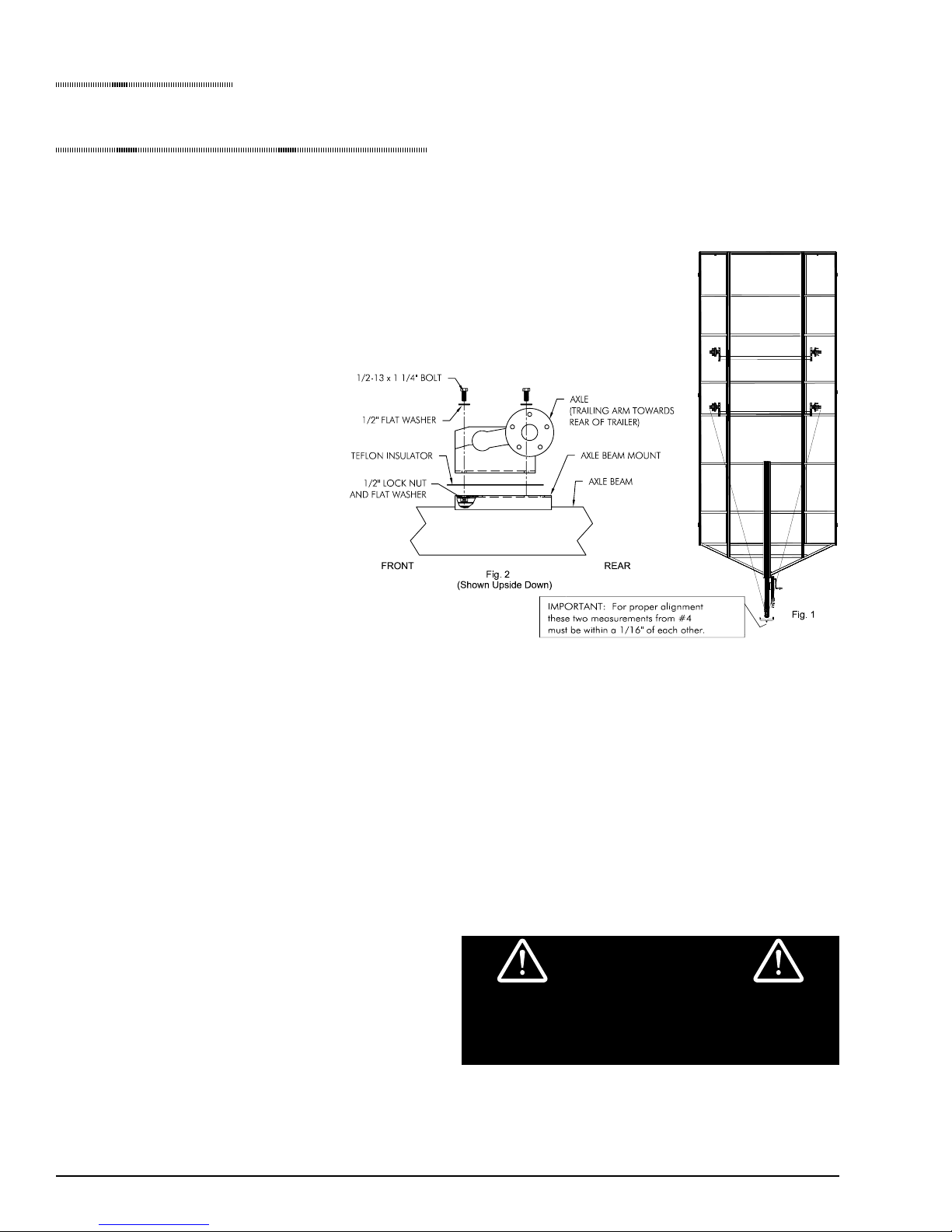
1. Place teon insulators on the axle beam mount and line up holes.
Some trailers will have two sets of holes with the front set as the
standard location. The rear set can be used to add tongue weight.
2. Set axle(s) on top of Teon insulators so trailing arm taper is to the
rear of trailer. Start each of the four bolts but do not snug up yet. See
Fig. 1 and Fig. 2
3. Pick a point on the outer edge
of the axle(s) that can be easily
measured to on both sides. Measure
from the center of the coupler to
these points (g. 3). Adjust axles so
these two measurements are equal
to within 1/16”. If mounting more
than one axle, start with the rear
and work forward.
4. Tighten all four bolts to 75 ft/
Ibs. Recheck alignment.
WARNING
Multi axle trailers must be level when towing.
Failure to do so will result in excessive tire
wear and reduced braking power.
Page 6
Using your FLOE trailer
Hitch Selection
When selecting a hitch, there are four important
things to keep in mind:
• Ball size -- All FLOE tilt trailers use 2”
couplers.
• Load capacity -- Load should never exceed the
load capacity of your hitch.
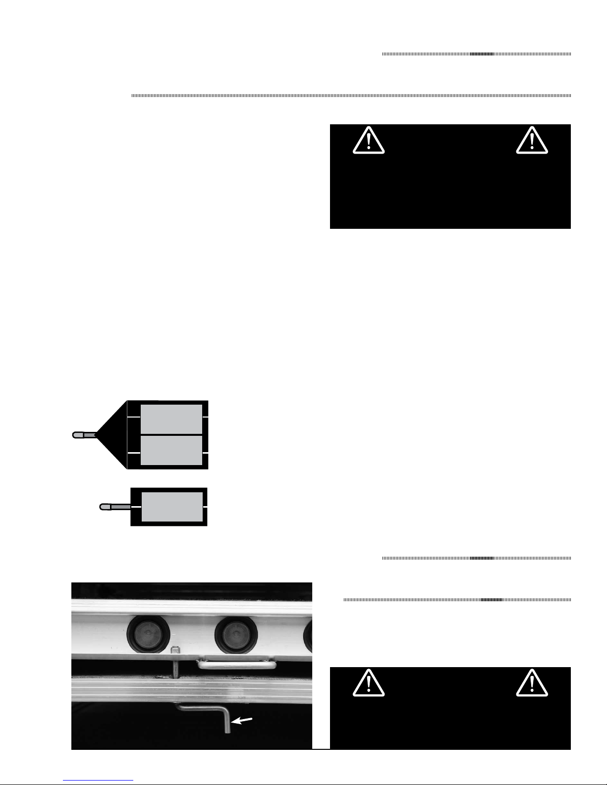
• In-set or out-set hitch -- FLOE recommends an
out-set or receiver-type hitch (See below).
• Hitch Height -- Hitch should be set so the trailer
is level.
- - - - - - - - - - - - - - IMPORTANT- - - - - - - - - - - - - -
Pulling a trailer that is not level could greatly
an uncomfortable and dangerous situation
while towing. It could also create excessive or
negative tongue weight which can cause either
tongue or axle damage.
Out-set Hitch (Recommended) In-set Hitch (NOT Recommended)
These illustrations show that
a trailer’s turning radius is
signicantly reduced when
towed by vehicles equipped
with an “in-set” hitch. To
reduce the risk of damage, we
recommend the use of an
“out-set” or “receiver-type”
hitch.
WARNING
When connecting your trailer to the towing
vehicle, it is important that your hitch coupler
is adjusted with the correct amount of force
for both smooth and safe trailer performance.
A loose connection may cause the coupler to
disconnect or to rattle. An over-tight coupler
This can also transmit unnecessary vibration to
your towing vehicle.
When turning or backing up, the towing vehicle
operator must exercise good judgement.
The manufacturer will not be responsible for
damage that results from the tongue or trailer
coming in contact with towing vehicle!
CAUTION
Page 7
Using your FLOE trailer
Hitch Coupler Adjustment
All FLOE models have a lever lock hitch coupler. On the lever lock coupler, the amount of locking force
can be adjusted to the diameter of the hitch ball. To change the amount of locking force against the hitch
ball:
1. Release the hitch coupler locking lever (to its straight up position).
2. Locate the adjustment nut on the bottom of the hitch coupler.
3. Rotate the nut on the threaded shaft counter clockwise to decrease tightness, or clockwise to increase
tightness.
4. Re-mount the trailer coupler on the hitch ball.
5. Push down the hitch coupler locking lever to its original locking position.
6. Repeat steps 1 through 5 until a snug t is obtained. (If you are unfamiliar with how tight to adjust
your coupler, consult your FLOE dealer.)
Using your FLOE trailer
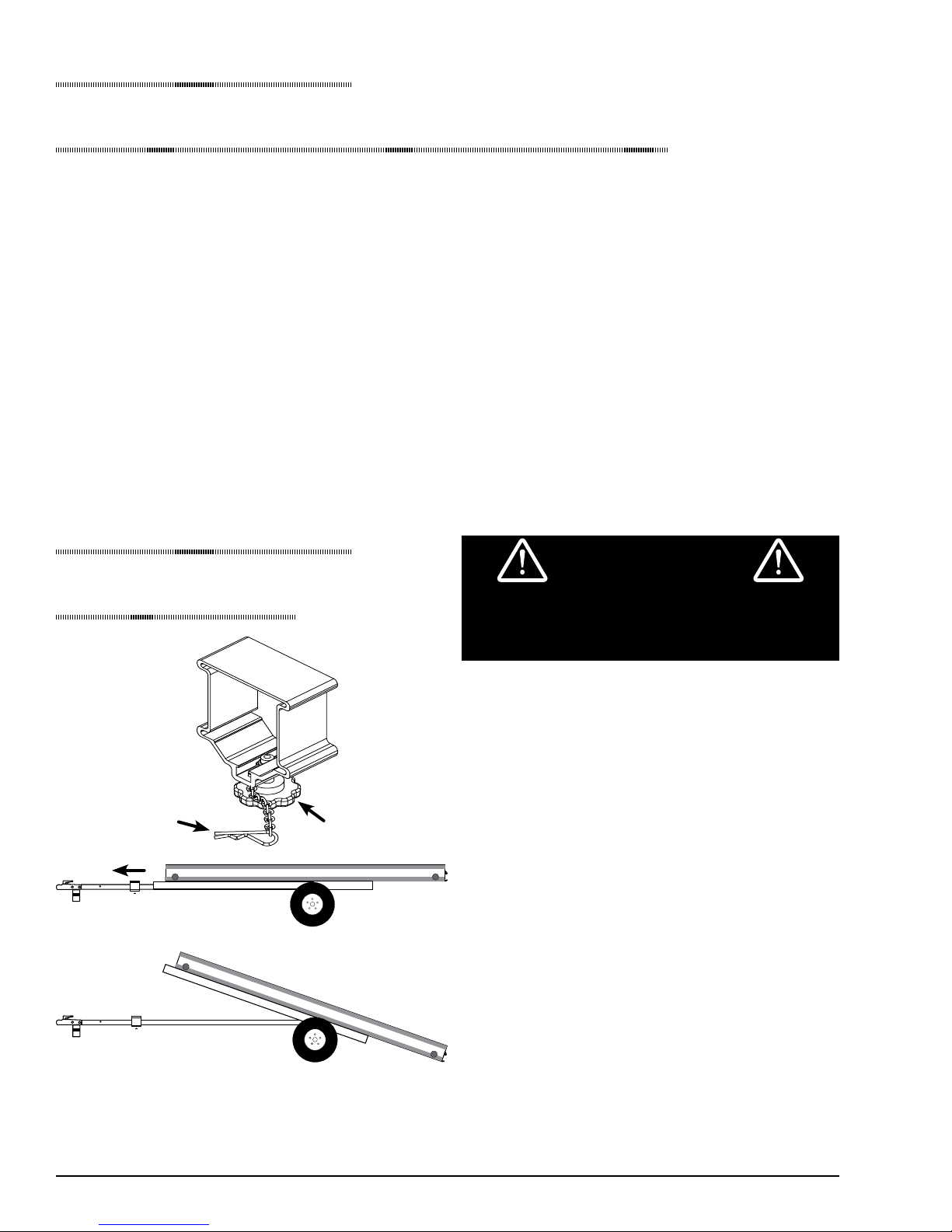
Tilt Clamp
Safety-pin
Slide clamp forward to tilt
Knob
WARNING
Failure to tighten tilt clamp and secure safety
pin before towing trailer could cause the trailer
to tilt while in transit.
The Floe tilt clamp eliminates the hassle and rattle
of a hitch pin design. To tilt, simply loosen Tbolt, remove the safety cotter pin, and slide clamp
forward. Slide back on, replace cotter pin, and
tighten when nished loading or unloading.
1. Loosen Knob on underside of tilt clamp.
2. Remove safety cotter pin.
3. Slide clamp forward.
4. To tilt trailer bed, either lift up on front of
trailer, or push down on rear of trailer.
5. Load trailer (see “Proper Loading and
Unloading” on page 7)
Trailer in tilted position
Note: If your trailer does not stay in the tilted position:
1. The tongue mounting bolt may not be tightened to
optimal tension.
2. A tilt-assist shock assembly is available as an accessory
for your FLOE tilt trailer. See page 18.
Page 8
6. Tilt trailer back to horizontal position by lifting
up on rear of trailer, or pushing down on front of
trailer.
7. Slide tilt clamp back to original position,
replace cotter pin and tighten Knob.
8. Secure your load before towing. (see pages 7-9)
Proper Loading & Unloading
Loads should be placed on the trailer so that
proper weight is applied to the tongue. Increase
or decrease the tongue weight by moving the
load forward or backward. When possible, loads
should also be placed to distribute equal weight to
all tires to prevent poor towing, axle damage, and
unequal or premature tire wear. See the diagrams
below for suggested load placement and tongue
weight. Unlike many trailers, the advanced design
of your FLOE trailer requires very little tongue
weight in order to minimize sway and to track
smoothly behind your tow vehicle.
The illustrations below are for typical placement
of snowmobiles. Use this information and
common sense for placing other loads as well.
Tongue weights are not strict maximums or
minimums, they are recommended ranges that
work well for the illustrated loads.
10’ & 12’ Tilt
Tongue Wt. 45-100 lbs
Ideal: 70 lbs.
Using your FLOE trailer
CAUTION
Failure to follow the steps below when loading
or unloading could result in damage to your
trailer, tow vehicle, snowmobile, and/or cause
possible severe or fatal injury to yourself and
others.
1. Never load or unload your trailer unless it is
properly connected to your tow vehicle.
2. It is imperative that your tow vehicle and trailer
are parked on level, even ground. Loading while
parked on an incline or uneven ground could
cause your trailer bumper to be at an improper
angle. This could catch your ski and cause
damage to your trailer, snowmobile and/or cause
severe or fatal injury.
3. Never load at speeds greater than 5 mph.
4. Ensure the trailer is fully tilted and that it will
stay in the tilted position until you have driven
on to it.
Be sure to securely
tighten crank handle
before each trip.
Utility
Tongue Wt. 25-80 lbs
Ideal: 50 lbs.
Crank Handle
5. After loading, make sure the tilt clamp is secure
and will not work itself loose while being
towed. Make sure the safety pin is attached.
6. Always test your footing before walking on the
trailer’s deck. It may get very slippery in cold,
wet and snowy weather.
Using your FLOE trailer
Securing Ramp
Be sure that you tighten the crank handle rmly in
place each time you travel and each time the ramp
is put into it’s storage position.
WARNING
the crank handle may result in the trailer ramp
becoming loose and falling out.
Page 9
Safety
Securing The Load
- - - - - - - - - - - - - - IMPORTANT- - - - - - - - - - - - - Although your FLOE trailer is equipped
with certain load securing features, it is the
responsibility of the operator to decide what is
necessary to properly secure the load for the
travel conditions.
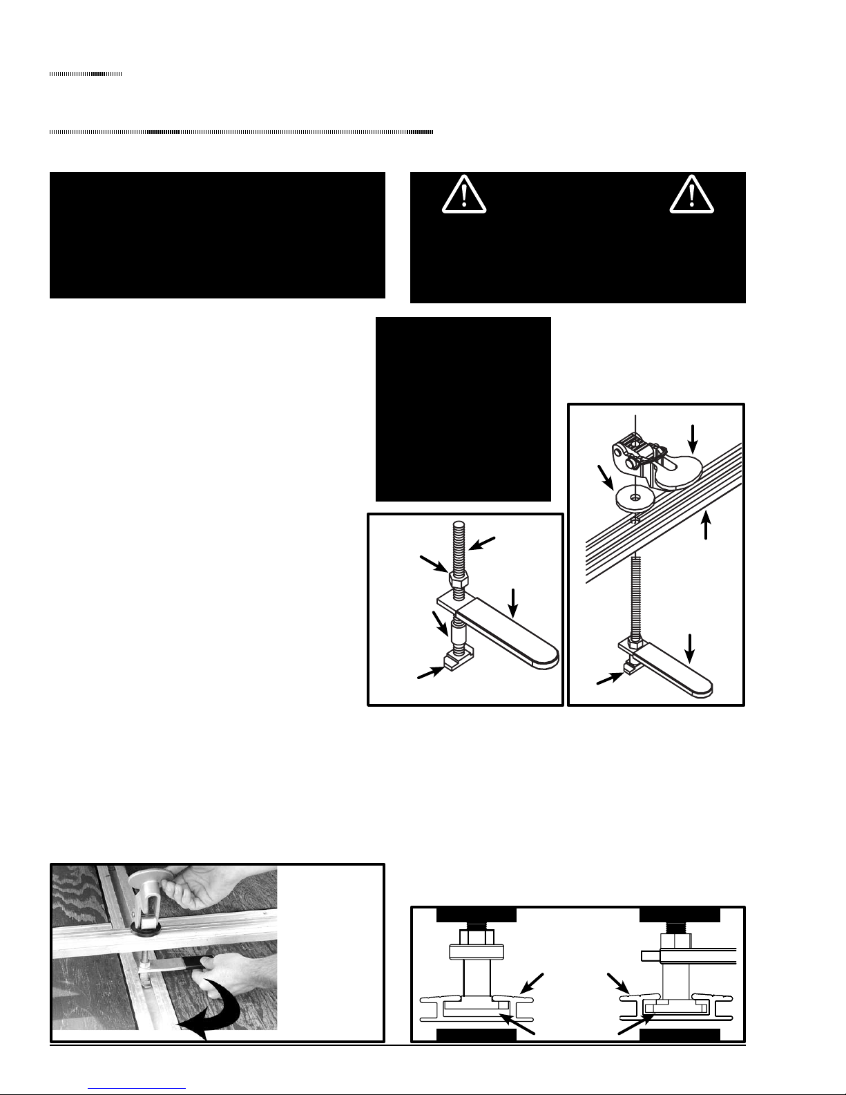
VERSA-LOCK ASSEMBLY INSTRUCTIONS
1. Slide spacer tube and handle over threaded
rod. Thread 1/2” nut down to handle and
tighten so handle is perpendicular (90º) to tie
down lock. Torque to 60 ft. lbs. See Fig. 4
2. Insert threaded rod through tie down bar
from the bottom. The tie down lock and
handle assembly should be on the bottom
(at) side of bar. Slide the plastic disc over
rod. Apply a liberal amount of anti-seize
lubricant onto the threaded rod. Screw the
lever assembly onto the rod until 1” of thread
is sticking out the top of lever assembly. See
Fig. 5.
3. Before using the Versa-Lock to secure a
load, read and understand the instructions on
how to use it.
Failure to read the Versa-Lock use instructions
prior to using it could result in severe damage
to the cargo it is meant to hold, cause a road
hazard, or even death.
- - - - IMPORTANT - - - Anti-seize lubricant
MUST be applied on
the threaded rod of
the Versa-Lock when
time and annually or
as needed to provide
peak performance.
FIG. 4
1/2” 20 Nut
Spacer Tube
Tie Down Lock
Threaded Rod
Handle
WARNING
FIG. 5
Plastic
Disc
Tie Down Lock
Lever Assembly
Tie Down Bar
Handle
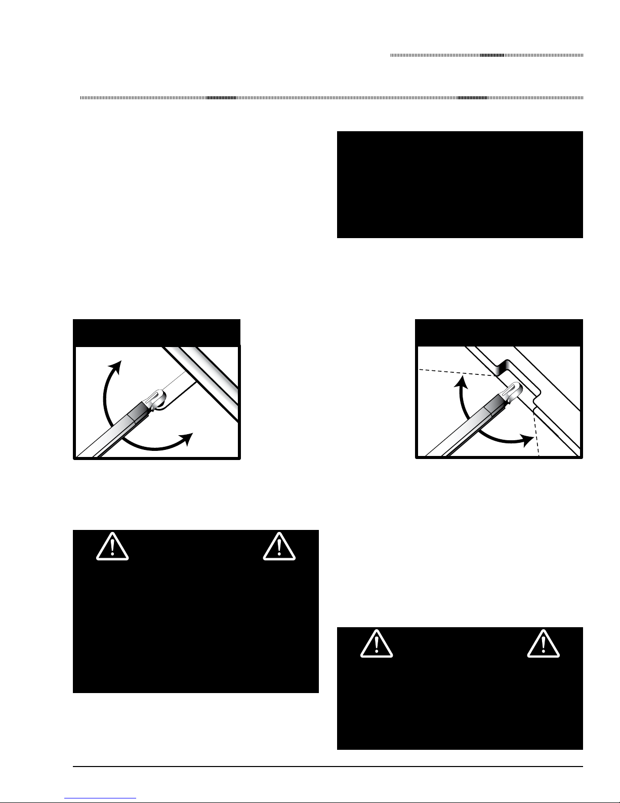
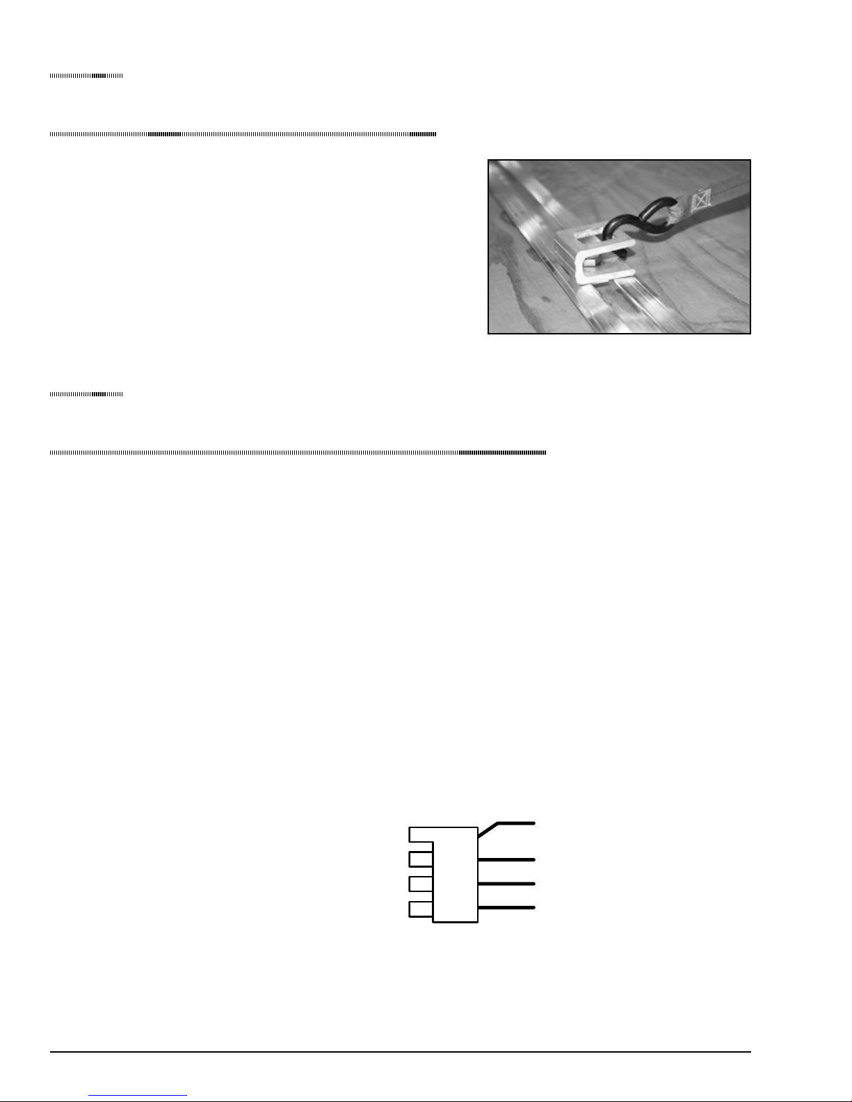
VERSA-LOCK USE INSTRUCTIONS
1. With the snowmobile loaded on the trailer, place the tie-down bar on the skis, insert the tie-down lock
into the Versa-Track™ on the trailer and turn handle 90º. See Fig. 6. The handle should be parallel (in
line) with Versa-Track and directly below the lever assembly. Ensure tie-down lock is properly seated
as shown in Fig. 7, by lifting handle and moving from side to side until lock is completely square
across track.
Insert tie down
lock and turn 90º
Page 10
FIG. 6
CONTINUED NEXT PAGE
FIG. 7
Versa-Track
Tie down lock
IncorrectCorrect
IncorrectCorrect

Safety
Securing The Load
CONTINUED FROM PREVIOUS PAGE
2. Crank the lever assembly down until it is a
maximum of 3/8” from the plastic disc when the
tie-down bar is sitting on the skis. See Fig. 8.
3. To clamp tie down bar in place, pull up on
handle and move side to side to make sure tie
down lock is seated properly in Versa-Track.
See Fig. 7. Use your other hand to push down
on lever assembly while still pulling up on
handle. Pulling the handle up keeps the tie-down
assembly in vertical position and allows it to
clamp down much easier. See Fig. 9. If more
or less holding pressure is desired, simply lift
lever up and turn clockwise to tighten or counter
clockwise to loosen.
4. With the Versa-Lock in the clamped position,
insert the safety snap pin to hold the lever
assembly down. See Fig. 10. A padlock (not
included) may be used instead of the snap pin
for added security. Failure to insert the safety
snap pin or padlock will result in the load
becoming unsecured.
Lever Assembly
3/8” Max.
Plastic Disc
Handle
FIG. 8
FIG. 9
FIG. 10
5. A recommended Quick Loop and strap for rear
tie-down is shown in Fig. 11. Fig 12 shows a
properly installed Versa-Lock with tie-down bar.
Note: If the Versa-Lock is used on a different
snowmobile, it may need to be adjusted up or
down for varying ski heights.
CAUTION
As with any tie-down system, the ultimate
responsibility for ensuring that the load is
adequately secured lies with the driver. At
a minimum, FLOE recommends the use of a
properly tensioned tie-down bar and a means
to secure the rear of the snowmobile (as
shown in Figs. 11 & 12). You may choose to
do more or less, based on road conditions and
when determining load-securing measures,
and periodically check your load to ensure
security is maintained.
FIG. 11
FIG. 12
Page 11
Safety
Securing The Load
QUICK-LOOP™ INSTALLATION
Lubricate the threads of the bolt with Anti-seize.
Insert the Quick Looop assembly into the Versa-Track. Rotate
the cam until the insert catches in the Versa-Track. While
pulling up on the Quick Loop, tighten until insert stays engaged
with slot. Slide the Quick Loop to the desired location and
nish tightening the bolt. Quick Loops should be installed so
that the pull is as close to perpendicular as possible.
Safety
Trailer Lighting System
Special emphasis has been placed on the design of
your FLOE trailer’s lighting and wiring system to
ensure that it is long-lasting and maintenance-free.
FLOE uses high quality lights that are commonly
found on commercial over-the-road trailers.
SIDE MARKER LIGHTS (Amber and Red)
• Shock-mounted (on replaceable rubber
grommets)
• Waterproof sealed units (for longer life)
• Easy to replace
• Small enough to carry spares
REAR TAIL/BRAKE/TURN SIGNAL LIGHTS
• Standard size
• Easy to replace and to carry spares
TONGUE CONNECTOR AND HARNESS
• Electrical connector has a molded harness for
long lasting durability. Your trailer is equipped
with a plug-in receptacle to keep the electrical
connector protected when not in use.
• Tongue portion of wiring harness can be replaced
without having to splice or replace the remaining
wiring harness.
• Wire harness is run through the trailer frame to
keep it protected from the elements.
• To ensure trouble-free use, periodically inspect
all connections for tight, corrosion-free contact
and apply an electrical grease as necessary to
prevent future corrosion.
White - Grounds all lights
Brown - Front & rear marker lights
3 light ID bar & tail lights
Yellow - Left turn / brakes
REAR ID MARKER LIGHTS, FRONT/REAR
CLEARANCE LIGHTS
• Standard size
• Easy to replace and to carry spares
Page 12
Green - Right turn / brakes
The wiring diagram provides the information
needed for wiring the towing vehicle harness/
connector. It is important that the proper
connections be made and that the system is tested
before using your trailer.
 Loading...