

Page 1
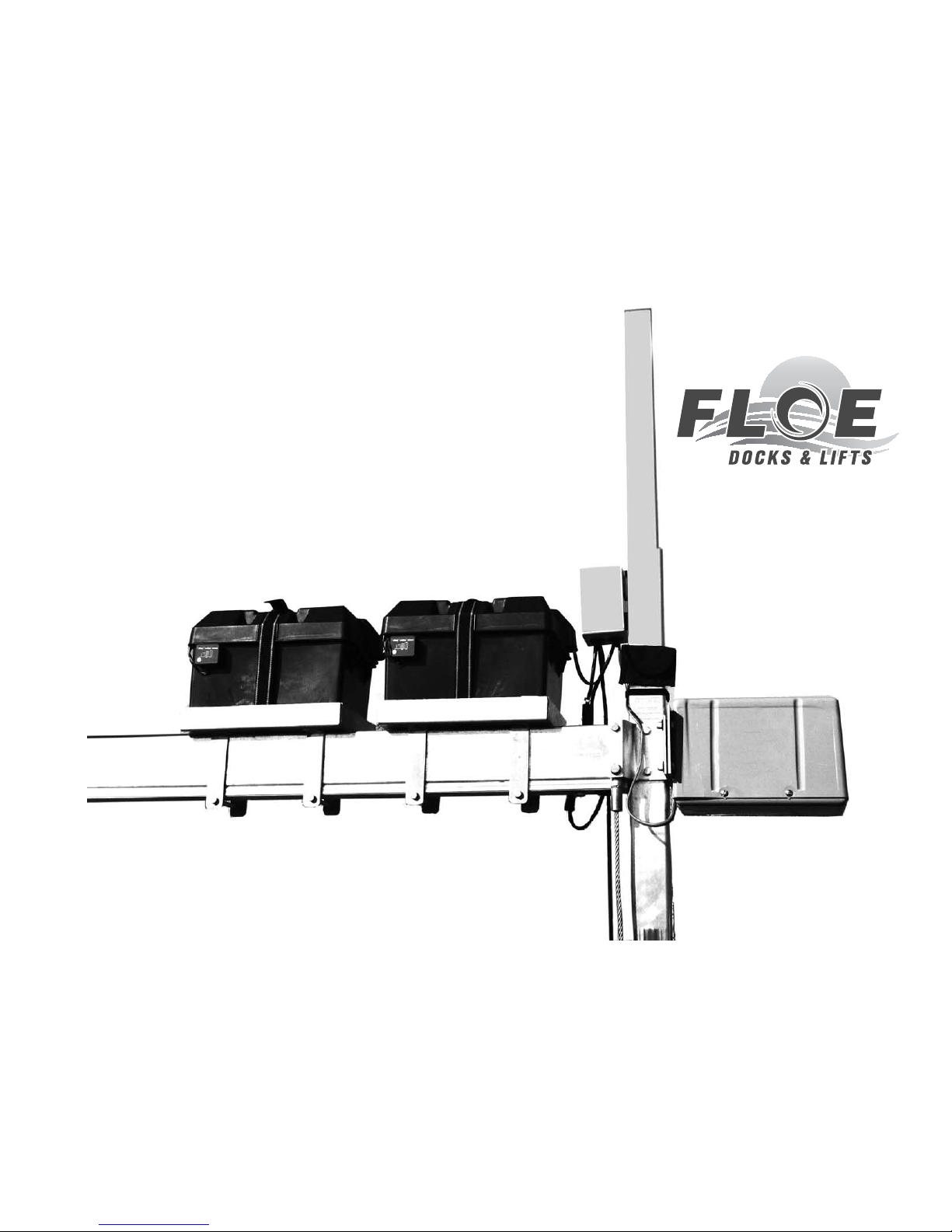
FLOE 24 vOLt vSD DrivE
3800, 5000, 6000, 6500 & 8000# LiFtS
P/Ns 511-38500-00, 511-60020-00, 511-80020-00
ASSEMBLY iNStrUCtiONS
TOOLS REQUIRED:
(2) 3/4” socket or wrench for 1/2”
nuts and bolts
(1) 9/16” socket or wrench for 3/8”
nuts and bolts
(1) Flat tip screwdriver
(1) Torque wrench
INSTRUCTION P/N: 611-50025-00
ISSUE DATE: 9/11/13
REVISED: 9/28/17
Manufactured By:
Floe International, Inc.
48473 State Hwy. 65
McGregor, MN 55760
Page 2

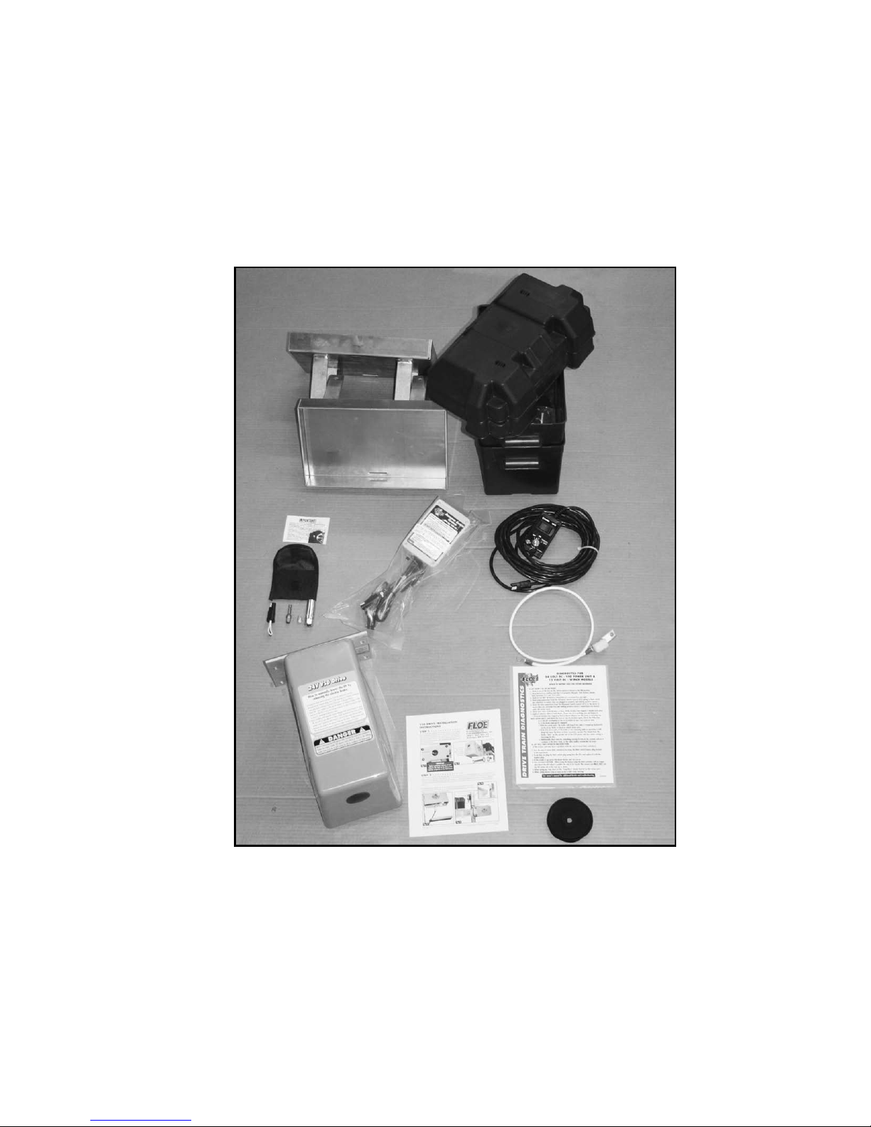
PARTS LIST
(1) Two – Battery Box w/Volt Meter, Cover & Strap, 111-00461-00
(2) One – Packet of Anti-Seize
(3) One – VSD Tool Kit
One – Tool Kit Pouch, 007-03980-00
One – 3/8” Drive Socket Adapter, 007-03981-00
One – Grease Gun Adapter, 007-03982-00
One – VSD Limit Switch Test Plug, 007-05293-00
One – Socket, 5/8” Deep Well, 007-03984-00
(or 5/16” Nut Setter, 007-03985-00)
(4) One – Diagnostic Checklist, 007-05305-00
(5) 3.3 yards. – Double Sided Velcro, 014-02310-00
(6) Two – Battery Tray weldments, 111-00014-00
(7) One – Wired Remote, 111-70010-00
(8) One – Battery Interconnect with Circuit Breaker,
111-70015-00 included with 511-38500-00
111-70017-00 included with 511-60750-00
(9) One – 24 Volt DC Advanced Switch Control, 311-50030-00
(10) One - 24 Volt DC Drive Motor
511-45018-01 included with 511-38500-00
511-60025-00 included with 511-60020-00
511-80025-00 included with 511-80020-00
(11) One – 24 Volt DC Installation Instructions, 611-50025-00
Page 2 of 8
Please refer to Page 3 for a
visual reference of parts.
Page 3
Page 3 of 8
7
8
6
5
10
11
9
3
4
2
1
Page 4
STEP 1 - - - - - - - - - - - - - - - -
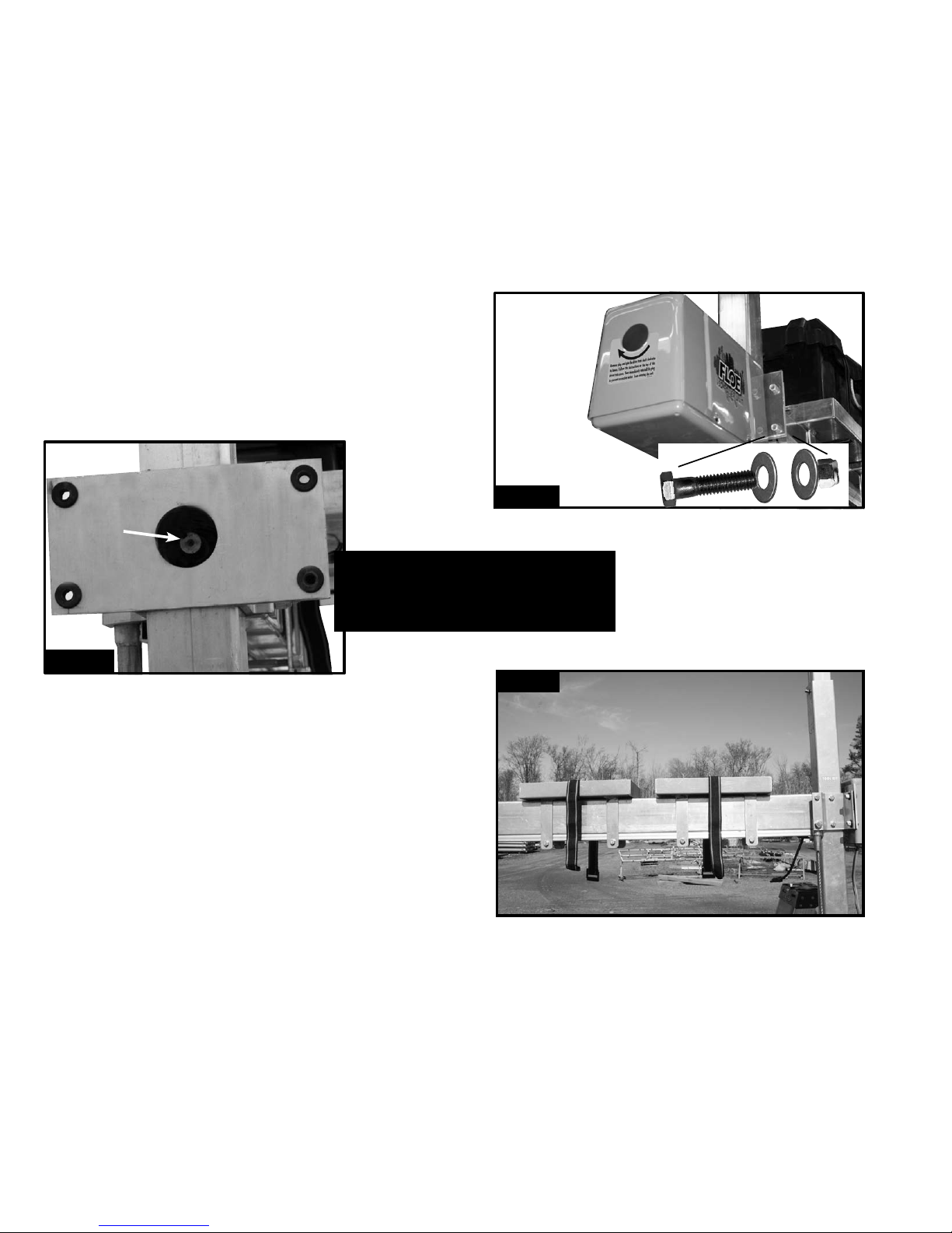
With the lift frame assembly done the VSD Drive Train and electronics can now be installed.
Apply a generous amount of anti-seize to the inside of the rigid coupler (Fig. 1A). Then attach
the “VSD Power Unit” to the “ball screw clamp” using four 3/8” x 1 3/4” bolts, four nylock
nuts, and eight at washers as shown (Fig 1B). Torque to 10 ft/lbs. NOTE: The motor shaft
and the rigid coupler are keyed and must be aligned.
Fig. 1A
Apply anti-seize
Fig. 1B
Attach using four
3/8” x 1 3/4”
bolts, four nylock
nuts, and eight
at washers
- - - - - - - - - IMPORTANT - - - - - - - - -
Apply a generous amount of
Anti-Seize to the inside of the rigid
coupler attached to the Ball Screw.
STEP 2 - - - - - - - - - - - - -
Attach the battery trays to the ball screw tube. The rst one 8” from the
corner post and the second 3” from the rst using the (4) 3/8 x 5 -1/2”
bolts and (4) 3/8” nylock nuts included with the lift frame hardware. The
offset side of the battery tray should be positioned to the outside of the lift
to provide clearance inside the lift. (Fig. 2) Torque to 25 ft/lbs.
Page 4 of 8
Fig. 2
Page 5
STEP 3 - - - - - - - - - - - - - - - - - - - - -
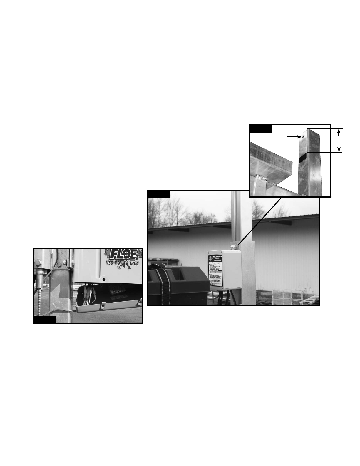
Clean and adhere the dual lock 5-1/4” down from the top of the corner post. (Fig. 3A) Attach the Advanced
Switch Control (ASC) to the hole in the top of the corner post with the nut, bolt, and washer provided.
(Fig. 3B) Connect “Advanced Switch Control” to the “VSD Power Unit” by removing the four screws in the
bottom cover. Inside the power unit is four wires with spade connectors. Connect these four wires with
spade ends to the wires on the Advanced Switch Control (ASC) with the corresponding
ends (Fig. 3C). The two small gauge wires on the ASC have female spade connectors
and it does not matter to which small gauge on the VSD power unit that they
connect to. The larger two wires have one male and one
female connector so they cannot be incorrectly wired.
Replace the cover on the bottom of the VSD Power Unit.
Fig. 3C
Attach the Advanced Switch
Control to the winch post by
pressing Dual Lock pads together.
Fig. 3A
Fig. 3B
51/4”
Page 5 of 8
Page 6
STEP 4 - - - - - - - - - - - - - - - - - - - - - - - - - - -
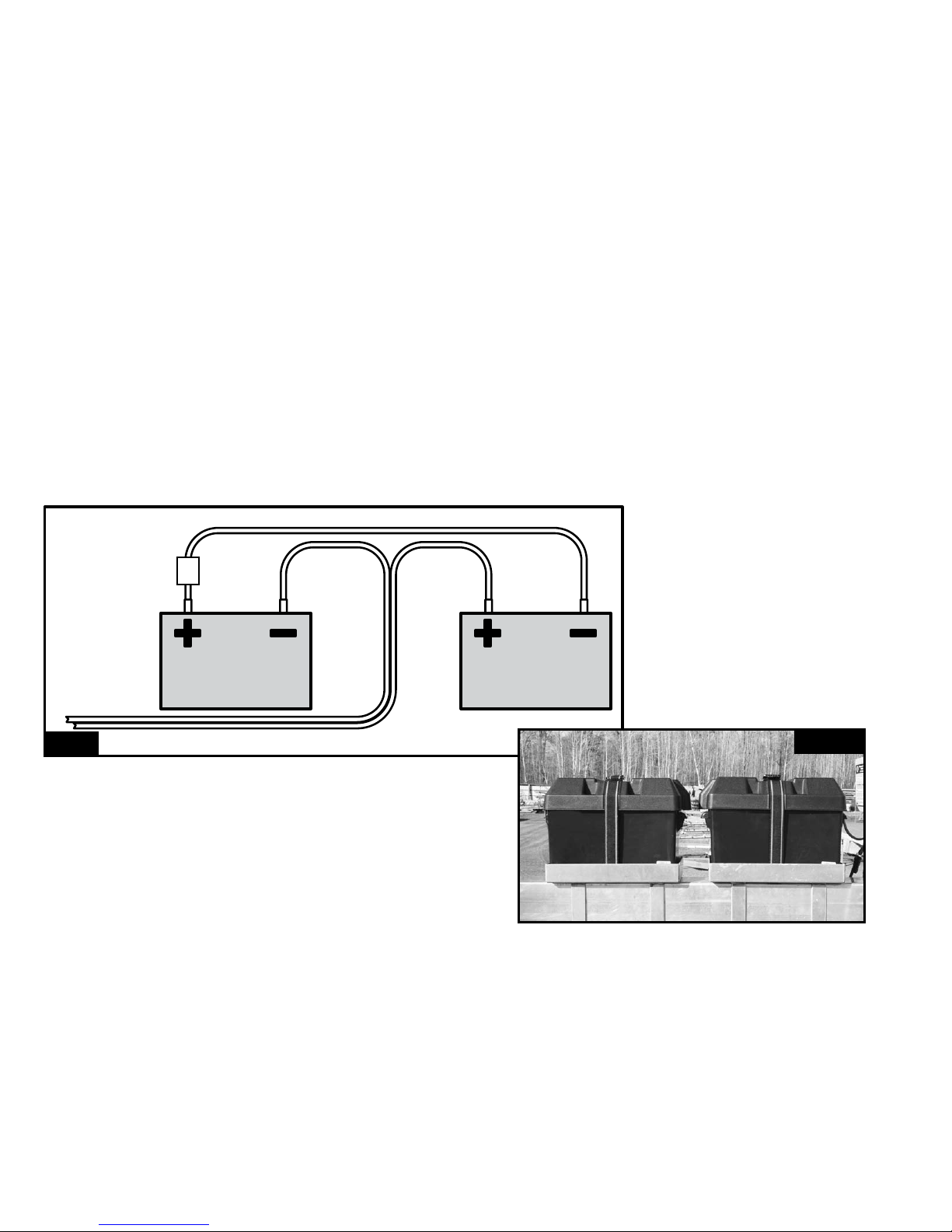
Connect the two remaining wires coming out of the Advanced Switch Control (ASC) box to the batteries. The two wires on the
Advanced Switch Control have ring connectors. One ring connector is red and the other is black and red. Connect these wires using
the diagram (Fig. 4A). Connect the red wire to the positive post on the second battery and the black/red wire to the negative post
on the rst battery. Connect the Battery Interconnect cable between the two batteries use the diagram (Fig. 4A) as a reference. Also
at this time attach the Battery Volt Meter leads (red to Positive and black to negative) of each battery. Example (Fig. 4B). Place the
diagnostic Check List in the battery box for future reference. Replace the battery box covers and secure them with the strap.
RED connectorBLACK connector
Battery Interconnect wire
to Electronic Control Box
Fig. 4A
Page 6 of 8
Fig. 4B
BATTERY #1
BATTERY #2
Page 7
STEP 5 - - - - - - - - - - - - - - - - -
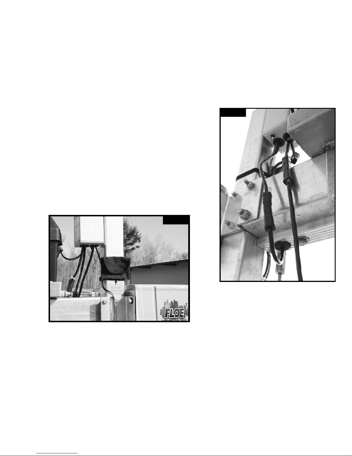
Plug 4 connector wired remote into the corresponding lead of the Advanced System
Control box. Note: The wired remote lead is identied by the blue wire tie next to the base
of the plug on the ASC as shown. Plug the 4 connector limit switch lead protruding from
the bottom of the limit switch housing to the corresponding plug on the ASC.
Note: The ASC Limit switch plug does not have a color coded cable tie attached.
(Fig. 5A) Attach the adhesive-backed tool kit to the lift frame, so that these tools are
readily available when needed, by cleaning the area above the tool kit decal and
removing the protective backing and pressing it to the corner post as shown in (Fig. 5B).
Page 7 of 8
Fig. 5A
Fig. 5B
TOOL KIT
Page 8
STEP 6 - - - - - - - - - - - - -
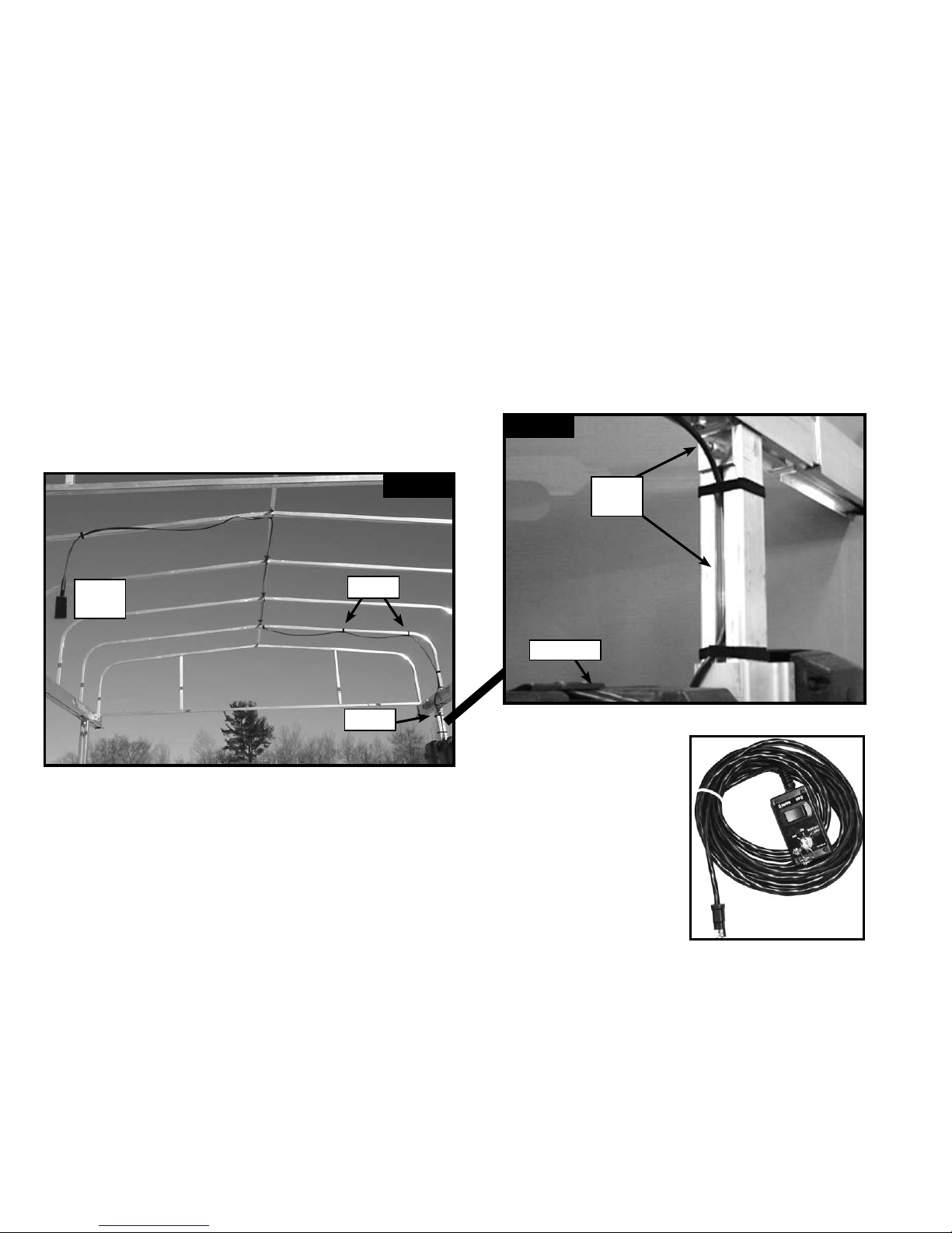
Secure all loose wires and the wire from the wired remote to the lift
structure by cutting off pieces of the included double sided Velcro. The
best way to secure the wired remote is to go up from the Advanced Switch
Control and attach the wire to the inside of the canopy frame if you have
one. Then come down from the canopy frame to the side of your lift that is
against the dock. (Fig. 6A) and (Fig. 6B)
Page 8 of 8
Wired Remote
Fig. 6A
Wired
Remote
Velcro
Velcro
Fig. 6B
Wired
Remote
Battery Box
 Loading...