

Flo Corp TRACER 1000 LTT1 Operating Instructions Manual
OPERATING INSTRUCTIONS
TRACER 1000™ LTT1
GUIDED WAVE RADAR LEVEL TRANSMITTER
(877) 356-5463 | (p) 330-331-7331 | (f) 330-331-7172 | www.FLO-CORP.com | © 2017 FLO-CORP | REVA 1116 1

Introduction
Please read carefully! No liability can be accepted for damage caused by improper use or installation of the Tracer 1000 Level Transmitter.
Featuring TDR (Time Domain Reectometry) technology, the Tracer 1000™ provides continuous radar level measurement
and point level detection in liquids and solids, with analog and switching output. This innovative radar device has almost
no installation restrictions – the 1” radar beam can be mounted in small tanks, tall and narrow nozzles and it measures
precisely even with difcult tank geometries or close to interfering structures. Factory settings may be congured via
HART® Communication protocol. Tracer 1000 is ideal for various types of processing and storage applications and has
an exceptional performance in liquids even with low reectivity such as light oils and hydrocarbons.
Safety Precautions
If you are unsure of the suitability of a Tracer 1000 for your installation, please consult your FLO-CORP representative for
further information.
NOTE: REMOVE ALL PACKING INSERTS BEFORE OPERATING LEVEL TRANSMITTER.
Authorized Personnel
All operations described in this operating instructions manual must be carried out only by trained specialist personnel
authorized by the plant operator. During work on and with the device the required personal protection equipment must
always be worn.
Warning about misuse
Inappropriate or incorrect use of the instrument can give rise to application-specic hazards, e.g. vessel over ll or damage
to system components through incorrect mounting or adjustment.
General Safety Instructions
The user must take note of the safety instructions in this operating instructions manual , the country specic installation
standards as well as all prevailing safety regulations and accident prevention rules. The instrument must only be operated
in a technically awless and reliable condition. The operator is responsible for trouble-free operation of the instrument.
During the entire duration of use, the user is obliged to determine the compliance of the required occupational safety
measures with the current valid rules and regulations and also take note of new regulations.
Disclaimer
The information contained in this document is subject to change without notice. FLO-CORP makes no representations or
warranties with respect to the contents hereof and specically disclaims any implied warranties of merchantability or tness
for a particular purpose.
(877) 356-5463 | (p) 330-331-7331 | (f) 330-331-7172 | www.FLO-CORP.com | © 2017 FLO-CORP | REVA 1116 2
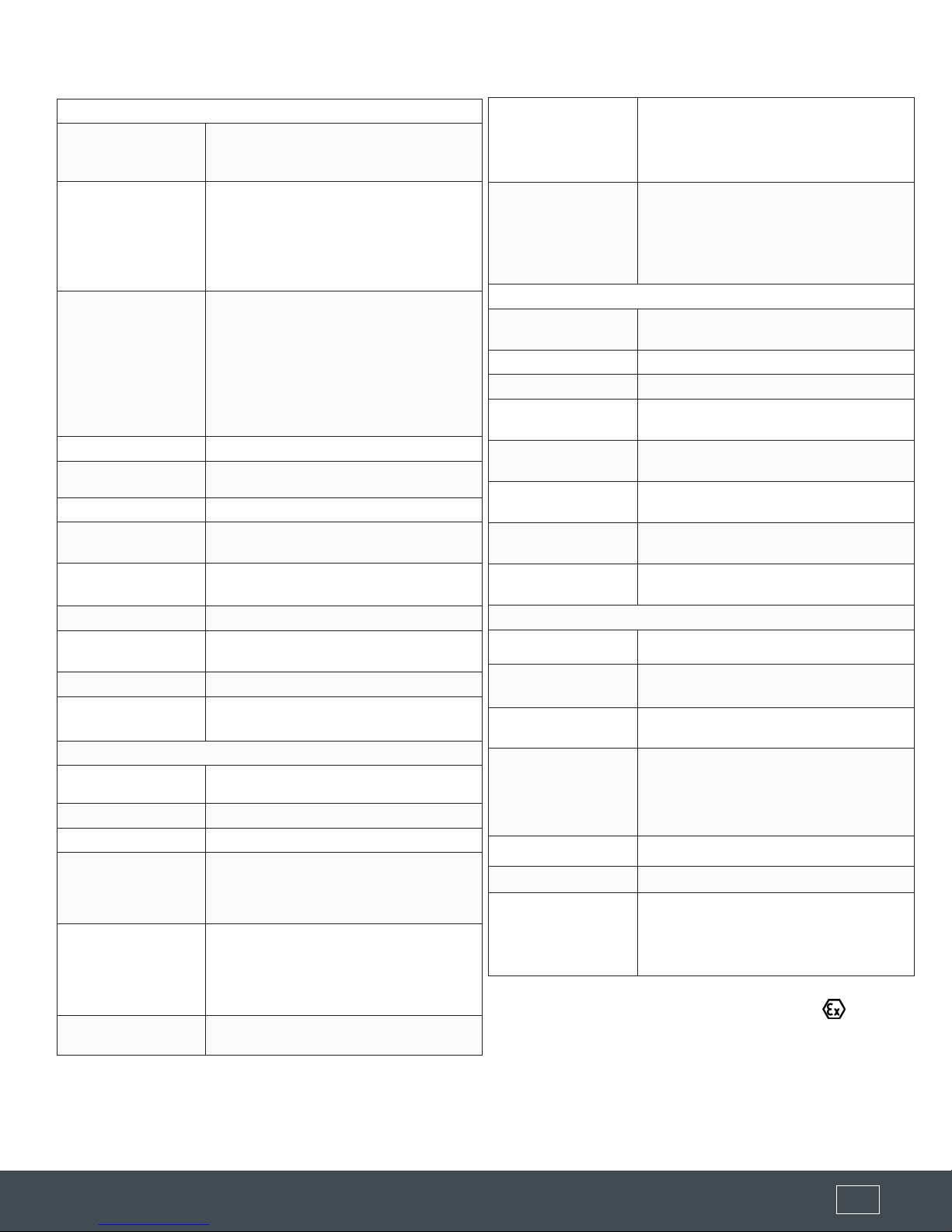
SPECIFICATION
Output Functions
Analog Output
(Active)
Total Load
Resistance
Lower Range Value
Upper Range Span
Response Time
Temperature Drift
Switch Output
Supply Voltage
Current
Consumption
Start-Up Time
Cable Terminals
Measurement Specications
Accuracy
Repeatability
Resolution
Probe Type
Probe Length [L]
Top Dead Band
Electrical Specications
The Tracer 1000 is an active, single
ended, non-isolated, 3 or 4 wire analog
output transmitter.
Current output 4-20mA: The span
between the lower range value [4mA]
and the upper range value [20mA]
is equal to 0-100% of the continuous
level measurement reading as a factory
default. Output can be inverted.
< 500Ω: HART resistor approx. 250Ω
+ load resistance approx. 250Ω if the
current output is connected to a device
with an inner resistance of approx. 250Ω,
then there is no additional external HART
resistor necessary. In that case, the
HART modem is connected in parallel to
the current output wires.
4.0mA (span 0%)
20.0mA (span 100%)
0.5s (default), 2s 5s (selectable)
Less than .0078 in/ºF change in ambient
temperature
DC Switch, PNP, Active, Max. Load 200
mA Current.
12-30VDC (reverse-polarity protected)
< 50mA at 24 VDC (no burden)
< 6s
Screwless, cage clamp terminal block for
stranded and solid wires AWG 22-14.
± 0.12” or 0.03% of measured distance,
whichever is greatest
< .08”
< .04”
316 SS Rod: 1/4” Dia. (Coated Rod; 3/8” Dia.)
316 SS Coaxial: 3/8” Dia.
Wire Cable: 1/2” Dia.
316 SS Rod: 2.41” - 120”
316 SS Coaxial: 0” - 120”
Wire Cable: 2.41” - 480”
(Length must be specied when ordering - The reference point
is always the sealing surface of the connection thread - See
dimensional drawings)
0” Coaxial Probe
2.41” Rod or Wire Probe
Measuring Range
[M]
Up to 780” depending on probe type
Freely positionable within the measuring
range [M] Hysteresis can be set by
Switching Point [S]
dening seperate upper and lower
thresholds; if those are set at the same
position, the minimum hysteresis of .11”
applies
Application Specications
Dielectric Constant
[ɛr]
Conductivity
Density
Standard
Application Temp.
Optional
Application Temp.
Ambient
Temperature
Application
Pressure
Velocity of Level
Change
Wire & Cable Probe: Congurable
Coaxial Probe: 0
No restrictions
No restrictions
F: -40º to 410º
C: -40 to 150º
F: -320º to 500º
C: -195 to 260º
F: -13º to 176º
C: -25º to 80º
-14.50 PSI to 580 PSI
< 3.2 fps
Mechanical Specications
Wetted Materials
Enclosure Material
Enclosure Rating
1.4404 / 316L and PEEK, PTFE
Aluminum alloy EN AC-AISi9Cu3 (DIN EN
1706), Epoxy Spray (~70µm)
Standard: NEMA 6 (IP68)
Explosion Proof Option: ATEX NEMA 7
1/2” NPT (2) or
Cable Glands/Screw
Plugs
Cable Glands (2) or
1/2” NPT (1) & Cable Gland (1) or
M20 x 1.5 (2) or
M20 X 1.5 (1) & Cable Gland (1)
Connection Thread
Weight (Less Probe)
3/4” NPT (US) or 3/4” G (Metric)
1.99 lbs. (903.8 g)
FM: Class I Groups A,B,C,D
Certication
Class II Groups E,F,G; Class III; Type 4X
Class I, Div. I, AEx D IIC; IP66
Class I, Div. I, Ex d II C
Specications are subject to change without notice.
(877) 356-5463 | (p) 330-331-7331 | (f) 330-331-7172 | www.FLO-CORP.com | © 2017 FLO-CORP | REVA 1116 3 (877) 356-5463 | (p) 330-331-7331 | (f) 330-331-7172 | www.FLO-CORP.com | © 2017 FLO-CORP | REVA 1116 4
PROBE TYPE RECOMMENDATIONS
Probe Type Recommendations
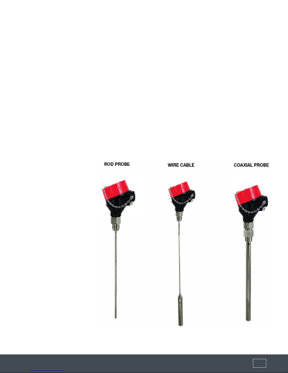
WIRE CABLE PROBE
316 SS ROD PROBE
316 SS COAXIAL PROBE
PROBE MOUNTING
Tall & narrow nozzles
Difficult tank or nozzle geometries
Close to internal tank structures or tank wall
Probe might move or touch internal tank structures/tank wall
Liquid spray may touch probe above the liquid surface
Non-stationary interface targets, e.g. agitator blades
Measurement readings at the very top or bottom of the tank
Non-metallic tanks
Bypass chambers and stilling wells
Limited headroom for installation
MEDIA CHARACTERISTICS
Measuring low reflectivity liquids (i.e. low dielectric constant)
Viscous, crystallizing, adhesive, coating, or sticky liquids
Fibrous liquids, sludge, slurry, pulp
Liquids containing solid particles
Clean-ability of probe is important
= Recommended
= Possible, maybe with configuration and/or mounting adjustments
= Not recommended
WIRE CABLE PROBE
316 SS ROD PROBE
316 SS COAXIAL PROBE
Tall tanks
Cable Probe Coaxial Probe
+ • •
+ • •
+ • •
+ • •
+ • •
+ • •
+ • •
+ • •
• + -
• • +
• • +
Bulk solids
+
•
-
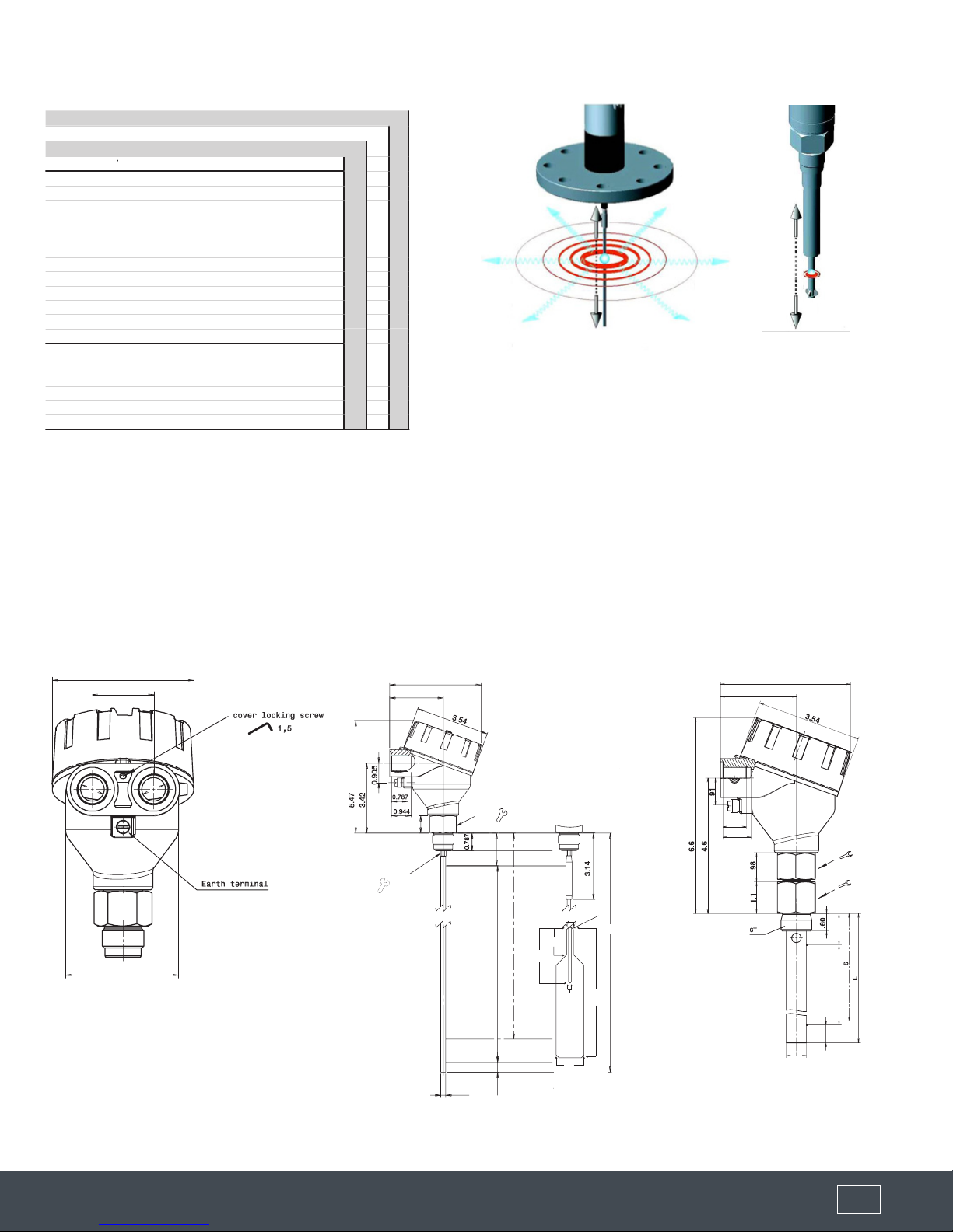
DIMENSIONS (Inches)
Housing
3.5
1.54
- - +
+ • •
- + +
- + +
- + +
- + +
316 SS Rod Probe / Wire Cable Probe 316 SS Coaxial Probe
2.55
65
4.4
D
3
90
39
cover locking screw
1.5
2
D
4.41
2.56
2.8
1/4”
72
Earth therminal
.79
.94
1.26
1.26
3/8”
1.259
CT
.375
(wire cable 7x19)
0.157
480 (wire rope 7x19)
0.236
1
1.5
M6x10, DIN914
set screw
0.47
12 M
6
.166
.75
5
M12x1.75
0.86
22
L
150
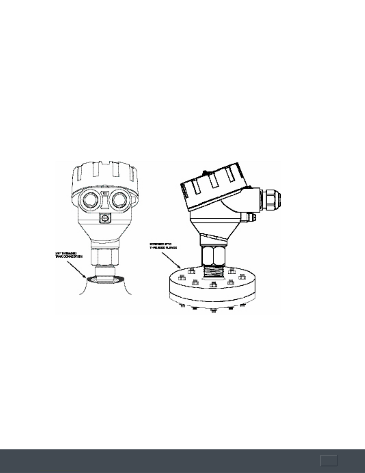
Installation/Mounting
Handling and Mounting:
The Tracer 1000 generally comes supplied with a 3/4” MNPT process connection used for mounting.
The Tracer 1000 is mounted vertically at the top of the tank via the process connection thread. The threaded
process connection can be screwed directly into a standard female threaded tank connection. We recommend
using Teon tape on the process connection. Please ensure proper sealing of the sensor connection and take into
consideration temperature, pressure and other process conditions. The tank connection can be either anged
or non-anged, standard tank nozzle or pipe union. The Tracer 1000 should never be welded onto the tank
connections. Welding directly on the metal parts of the Tracer 1000 will cause serious damage to the transmitter
and void the warranty. The G tting thread of the Tracer 1000 is supplied with a gasket made of Klingersil C-4400,
thickness 0.0787”. The suggested tightening torque is 25 Nm (max. permissible torque is 45 Nm) with a max.
pressure of 580 PSIG.
Preparation:
FLO-CORP’s Tracer 1000 level transmitters are ready to install as-is, and are completely pre-congured per the
application data sheet or customer application information at time of order. The Tracer 1000 is shipped with a
Figure 1: Mounting
calibration tag secured to the safety chain of the transmitter head. The calibration tag indicates the 4 mA equivalent
in level (usually 0.0”) and 20 mA equivalent in level (high level reading). If changes are to be made with this
conguration, please see section Operation and section Programming and Conguration.
Things to Avoid:
Avoid lifting or handling the Tracer 1000 by its probe; this can potentially damage the probe or the probe
connection. The Tracer 1000 should be handled by the hexagon connection or the lower section of the housing.
Avoid using the housing to screw the Tracer 1000 into the process connection. Use the hexagon tting to tighten
using a 1.25” wrench.
Avoid installing the Tracer 1000 probe so it is not directly impacted by liquids owing out of the lling inlet. This
may cause erroneous readings from the transmitter. If this situation is unavoidable, please consider the use of the
Coaxial Probe option.
Avoid installing the Tracer 1000 probe so it is touching or swaying towards other objects inside the tank, including
(877) 356-5463 | (p) 330-331-7331 | (f) 330-331-7172 | www.FLO-CORP.com | © 2017 FLO-CORP | REVA 1116 5 (877) 356-5463 | (p) 330-331-7331 | (f) 330-331-7172 | www.FLO-CORP.com | © 2017 FLO-CORP | REVA 1116 6 (877) 356-5463 | (p) 330-331-7331 | (f) 330-331-7172 | www.FLO-CORP.com | © 2017 FLO-CORP | REVA 1116 7 (877) 356-5463 | (p) 330-331-7331 | (f) 330-331-7172 | www.FLO-CORP.com | © 2017 FLO-CORP | REVA 1116 8 (877) 356-5463 | (p) 330-331-7331 | (f) 330-331-7172 | www.FLO-CORP.com | © 2017 FLO-CORP | REVA 1116 9 (877) 356-5463 | (p) 330-331-7331 | (f) 330-331-7172 | www.FLO-CORP.com | © 2017 FLO-CORP | REVA 1116 10
the tank nozzle. This may cause erroneous readings from the transmitter. Anchoring xtures are permissible and
supplied by the end-user. Please contact FLO-CORP for further details about using anchoring xtures.
Since the Tracer 1000 has an energy signature that is approximately a 1.5” to 2.0” radius from the center of the probe,
considerations should be made when engineering the proper probe location for mounting. If it is not possible to mount
the probe in a location that will be free of any objects that might interfere with the signal, than set-up conguration
changes can be made to possibly accommodate the mounting location (See Conguration Section).
Probe Selection
Probes for Liquids and Paste Applications:
The Tracer 1000 uses 1 of 2 possible probe congurations. The Rod probe is the most common. It can be used for
most liquids and is recommended for use with stilling wells and bypass chambers with a minimum inside diameter of
2.0”. The maximum length of the rod probe is 10 feet. The Rod probe is made of 316L Stainless Steel, 1/4” diameter.
The Rod probe can be ordered with an optional teon isolation sleeve and connections. Both congurations have a
threaded female connection on one end and bare end on the other. To install, thread the threaded connection into the
male threaded adapter on the Tracer 1000 transmitter.
The Coaxial probe is the second probe type available with the Tracer 1000. The Coaxial probe is typically used with
extremely low ∑r (dielectric) strength. It is also used if the agitation caused by inuent ow or mixing blades make the
level signal to erratic to read. The maximum length of the Coaxial probe is 10 feet. The Coaxial probe is made of 316
Stainless Steel, 1/2” diameter. To install, thread the threaded end of the inner rod into the threaded adapter of the Tracer
1000. Please make sure that the centering rod isolators are installed with approx. 20” space between each spacer.
The outer tube will now be ready
to slide over the inner rod, upward
towards the transmitter head. Next,
thread the threaded connection of
the outer tube into the upper hex
threaded connection. The Coaxial
probe assembly should now be
complete with the 3/4” male process
connection and is now ready to be
threaded into the 3/4” female tank
connection.
Figure 2: Probes
Wiring
Wiring Diagrams:
 Loading...