

Page 1

1
Floataway Installation Manual 230v 50Hz Tranquility 2017 - v3
Installation Manual
Tranquility 2017 [v3]
230v 50Hz
Revised March 2015
PLEASE READ THIS MANUAL TO THE END BEFORE STARTING
[ Updated : MAY 2017 ]
Floataway is a registered trademark of Cosine Limited.
8 Ironside Way, Hingham Business Park, Hingham, Norfolk, NR9 4LF, UK
Ofce +44 1953 851 515 Factory +44 1953 851 861
Info@oataway.com www.oataway.com
Page 2

2
Floataway Installation Manual 230v 50Hz Tranquility 2017 - v3
Please read through all the instructions before beginning the installation. This rst section
repeats the information which was supplied in our technical information for preparing the
oat room for a Floataway Float Pool.
Before You Get Started
Page.
• First check the room 3
• Inspect the proposed reception area. 3
• Plan where to put the salt and parts during the installation. 3
• Check the Cables / Electrical Supplies 4
The Installation : Sequence of Parts Required
Page
• The high temperature insulation panel 5
• The silicone heater membrane sheets 5
• The heater panels 5
• The tub 5
• The ground noise isolation system 6
• The skimmer and pre-lter 7
• The dome 7
• The door 7
• The hinges (tted to the door) 8
• The suction assembly and pump connections 9
• The lter connections and the back panel 9
• Water Isolation check 10
• The jacks / door motors 10
• The auto doser - liquid disinfectant 11
• The control box and its connections 14
• The control box diagrams 15
• The electrical supply cables 16
• The water level sensor 17
• The temperature probe 17
• The back-up battery 17
• XLR connectors 18
• Room light control 18
• Under water lights 19
• The air hose connections 20
• Music speaker 20
• Intercom system 21
• Music system 22
• Fitting the side panels 22
• Identifying parts of the LAN cable 23
• The remote control 24
• Recommended values 29
• The water and salt 30
• Troubleshooting common problems 31
• Remote Quick Guide 33
Page 3
3
Floataway Installation Manual 230v 50Hz Tranquility 2017 - v3
First check the room
The Float room needs to:
• Be big enough, min. 3.5m by 3m wide (11’6” by 9’10”).
• Have a oor loading capacity of at least 5kN per square meter.
• Have a waterproof, bunded*, non slip oor (e.g. Altro Marine 20)
• Have a 230v 50Hz electricity supply as needed
• Have ventilation (fan if no window)
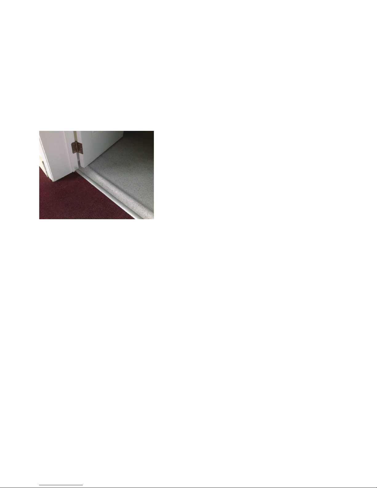
*Bunded means with raised edges so
that any leak is retained within the oor
area. Typical details are shown in the
photo below. Floataway will not be held
responsible for damage to adjacent room
oors or to ceilings below the oat room
if our advice has not been followed.
For commercial use, the room must:
• Have an emergency light
• Have appropriate re warning and escape
• Have appropriate disabled use equipment and signs, if applicable.
Check the access route through which the parts must be carried.
Inspect the proposed reception / centre
There must be a position for the CD player or sound source(e.g. iPad/iPod), and a place for the
remote control unit in the reception area. Check that the LAN cable has been installed for the
remote box. The remote control should not be easily accessible to the visiting public.
Check how much hot water will be available and if a hose will be needed to ll the product.
Plan where to put the salt and parts during the installation.
Page 4
4
Floataway Installation Manual 230v 50Hz Tranquility 2017 - v3
The Cables / Electrical Supply
The Data Cables:
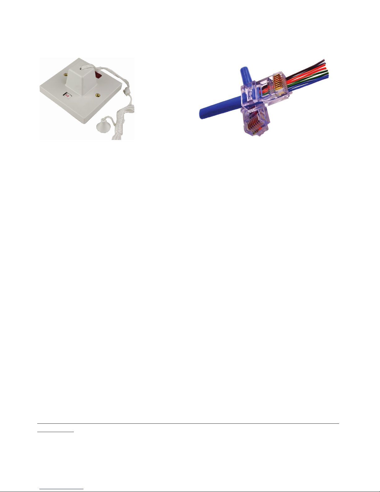
The control system uses standard Industrial CAT5/6 LAN cable and RJ45 sockets. It must not be
part of a network but have it’s own dedicated cable. The cable should be installed with the control
box and remote. A second LAN cable is required for an intercom option. We recommend installing
a spare LAN cable at this time in case of damage to the cable.
2x Cat 5 or 6 LAN cables direct (no breaks/routers) from the back of the tank to the location of
the remote. The second is spare, but highly recommended. You need a 3rd if you have intercom or
think you may add it in the future.
Electricity Supply:
There should be a waterproof connection outlets for the single phase 230v 50 Hz. Supply. The
mains supply should be in a waterproof terminal point (or socket in some countries) near to the
location of the technical pack.
1x 230v 50Hz supply - 20A
Check that the voltage of the pool is suitable for the supply installed.
Connecting a 110 V pool to a 230 V supply or a 230 V pool to a 110 V supply will cause damage to
the pool components and may be dangerous. The supply should have a two-pole interrupter such
as a ceiling pull switch in the room. This interrupter must have a suitable current rating for the fuse
or breaker on each supply. The interrupter switch must be 2m (6’) from the water line of the pool.
Fusing and RCD (Residual Current Device) or GFCI :
• The pool should be supplied through it’s own RCD or GFCI (differential) with a trip current
of 30 mA / Class A and through an isolating switch.
• There must also be a fuse or circuit breaker in the line.
• For 230v installations the fuse should be 20 Amp with suitable cables.
We recommend that the electrical installation of the supply be done by a suitably qualied
electrician.
Page 5
5
Floataway Installation Manual 230v 50Hz Tranquility 2017 - v3
Please read through this Manual before beginning the installation. If you are not condent
of success, please hire an electrician to do the installation for you. Floataway will not be
responsible for installation errors caused by not using these instructions.
The Heater Insulation Panel
The heater insulation is a thick high temperature rigid aluminium
coated mat. The tub sits on top of this piece and is positioned
approximately 8 inches from the back wall in the oat room.
The Silicone Heater membrane sheets
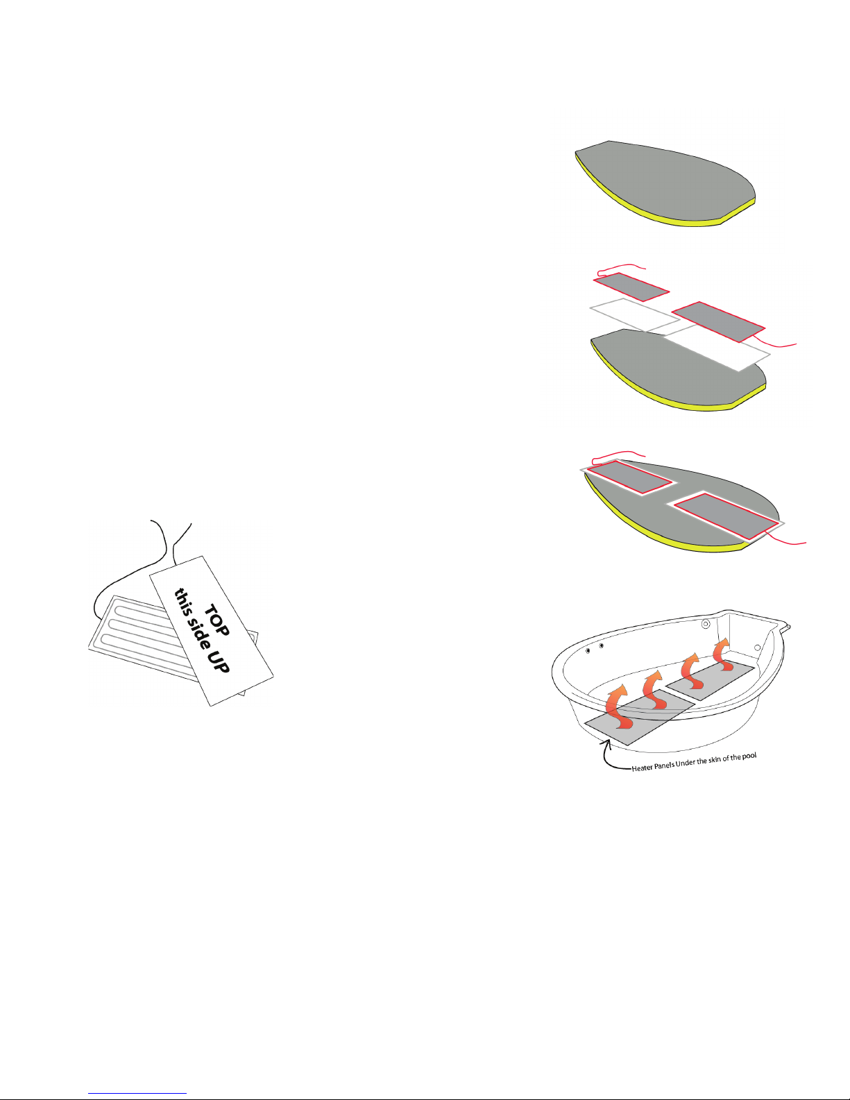
The heaters must sit on top of the silicone sheet membrane, it is
a white soft foamed rubber sheet 2mm thick. The silicone sheet
is WHITE and comes rolled up. Lay the silicone sheets down on
the insulation panel ready for the heaters.
The Heater Panels
The heater panels, smooth metal side facing upwards, are positioned over the high temperature insulation. The drawing below
shows both sides of the heater panel. Be sure that the coil sides
are facing the insulation so that you see the smooth side facing
you as shown below right.
The drawing shows the correct
position of the heater panels
The heater with a longer wire
goes at the front of the product.
The cables run back to the control box on the tank and should
not be trapped under the tub.
Check that there are no foreign bodies on the top surface of
the heater, or on the bottom of the tub, before the tub is added.
Small hard objects may break the bottom of the tub when water
is added, or cause local hot spots or noises.
The heaters are not supplied connected to the control box and must be fed through cable ties
along the tank and then the glands and connected to ground (5), neutral (2), series connection(8)
and switched live (Heater MCB 1) connections in the control box. (See connection information
under “control box” section.) A small portion of the heaters should stick out from under the tub (approximately an inch) to enable earth bond testing.
The Tub
Place the tub gently onto the insulation and heater panels. The heater panels and insulation may
be walked on during this manoeuvre. Remove any packaging from the tub and clean it thoroughly,
rst using soapy water, then if necessary lighter fuel (not acetone) for stubborn marks. Position
the tub so that its base sit exactly on top of the insulation.
Page 6
6
Floataway Installation Manual 230v 50Hz Tranquility 2017 - v3
Ground Noise Isolation System
The optional ground noise isolation system (GNIS) is designed to reduce the frequencies transferred through the ground into the water. The rubber springs will only work once the tank is lled
and salt is added as the system is designed for the working load of the product so will not work
correctly with the tranquillity empty.
Typical noises that can be heard through the water include road noise, toilets ushing, foot steps,
doors closing, these type of sounds can be transmitted through the oor due, the GNIS will reduce
these to give a superior oat experience.
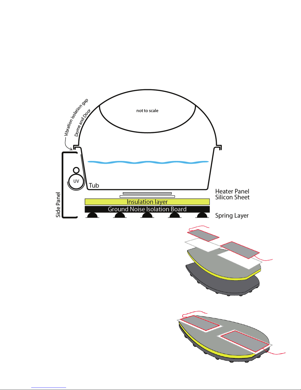
When installing, the heavy GNIS board is placed down
where the standard insulation would be tted, the insulation panel is thinner to account for the height difference.
The GNIS system will only work on the parts that
are then resting on top of the board. The side panels
around the Tranquillity do not sit on the board. It is very
important that the side panels do not touch the tub any-
where. The pump and sits on the oor and is connected
to the tub through a rubber hose, as is the lter housing
return pipe - these are the only parts that connect the
isolated tub to the ground.
The GNIS board can be seen here with the insulation,
silicone heater mats and heaters ready for the tub to
be placed down.
Page 7
7
Floataway Installation Manual 230v 50Hz Tranquility 2017 - v3
The Skimmer and Pre-Filter
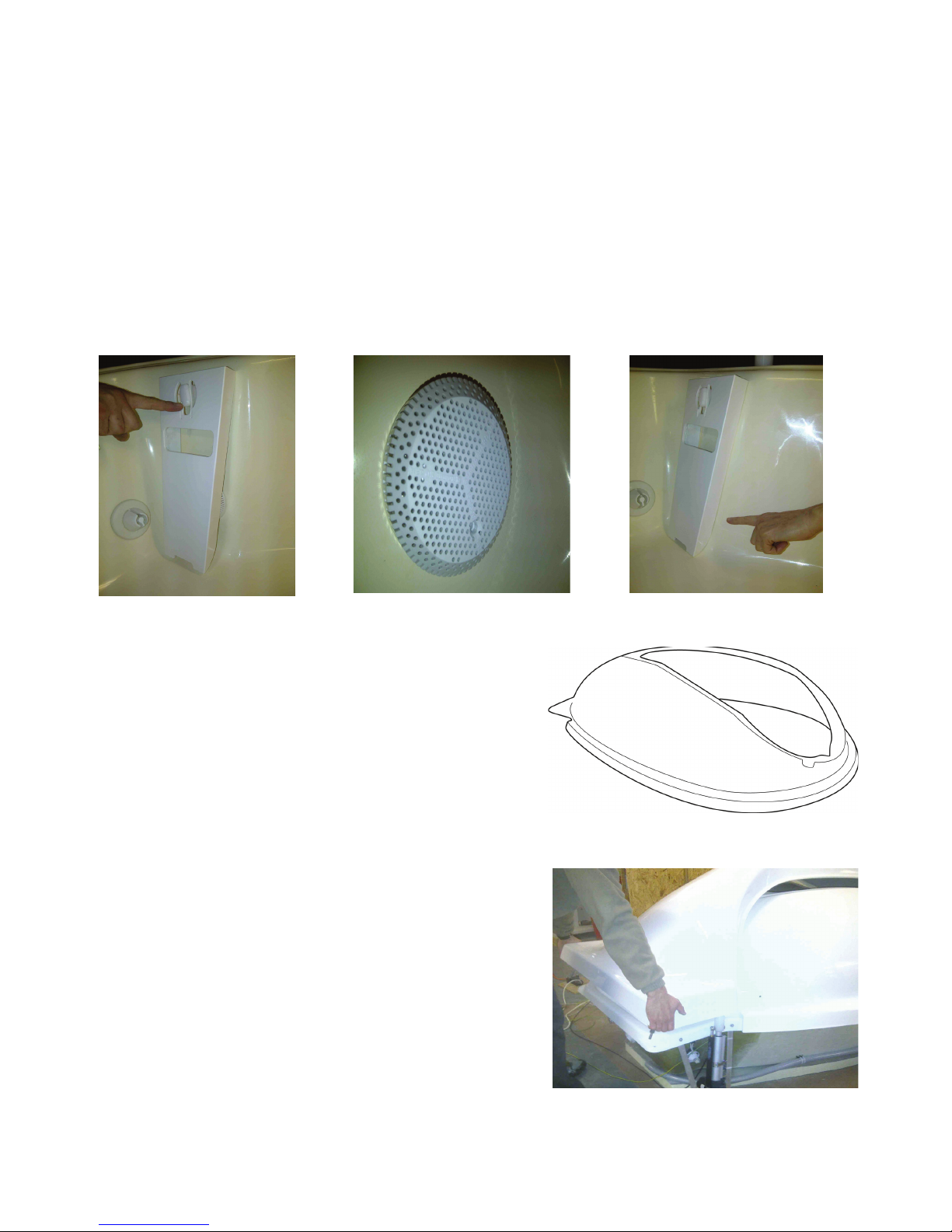
The skimmer is located at the back of the tub and is made of white plastic with a slot indicating the
correct water level (½” above the bottom of the slot) but is not shipped attached to the tub.
Remove it from the accessories box and put it in place as seen on the right hand photo below.
You will rst need to attach the skimmer to its clip (photo below left) at the top and then push the
bottom section over the prelter which comes attached to the tub (shown below in the middle), using some force. The prelter prevents debris such as earplugs entering the pump.
The skimmer’s correct position is ush against the tub (as shown below right). Do not be afraid to
give it a good strong “hit” to get it into its correct place. The skimmer and prelter must be re-
moved once per week for cleaning in soapy water.
The Dome
When the tub has been cleaned, carry the dome in and
place it carefully onto the tub. Note that the dome can be
removed for cleaning by lifting, even after the door is
tted.
Note : when in operation, Do not leave the dome off for
a prolonged period, when not in a oat session, the door
automatically closes if left open too long.
The Door
Bring in the door carefully and place it onto the dome. The
hinges are tted to the door and will need to be guided
into the mounting holes at the back of the tub.
Page 8
8
Floataway Installation Manual 230v 50Hz Tranquility 2017 - v3
The Hinges
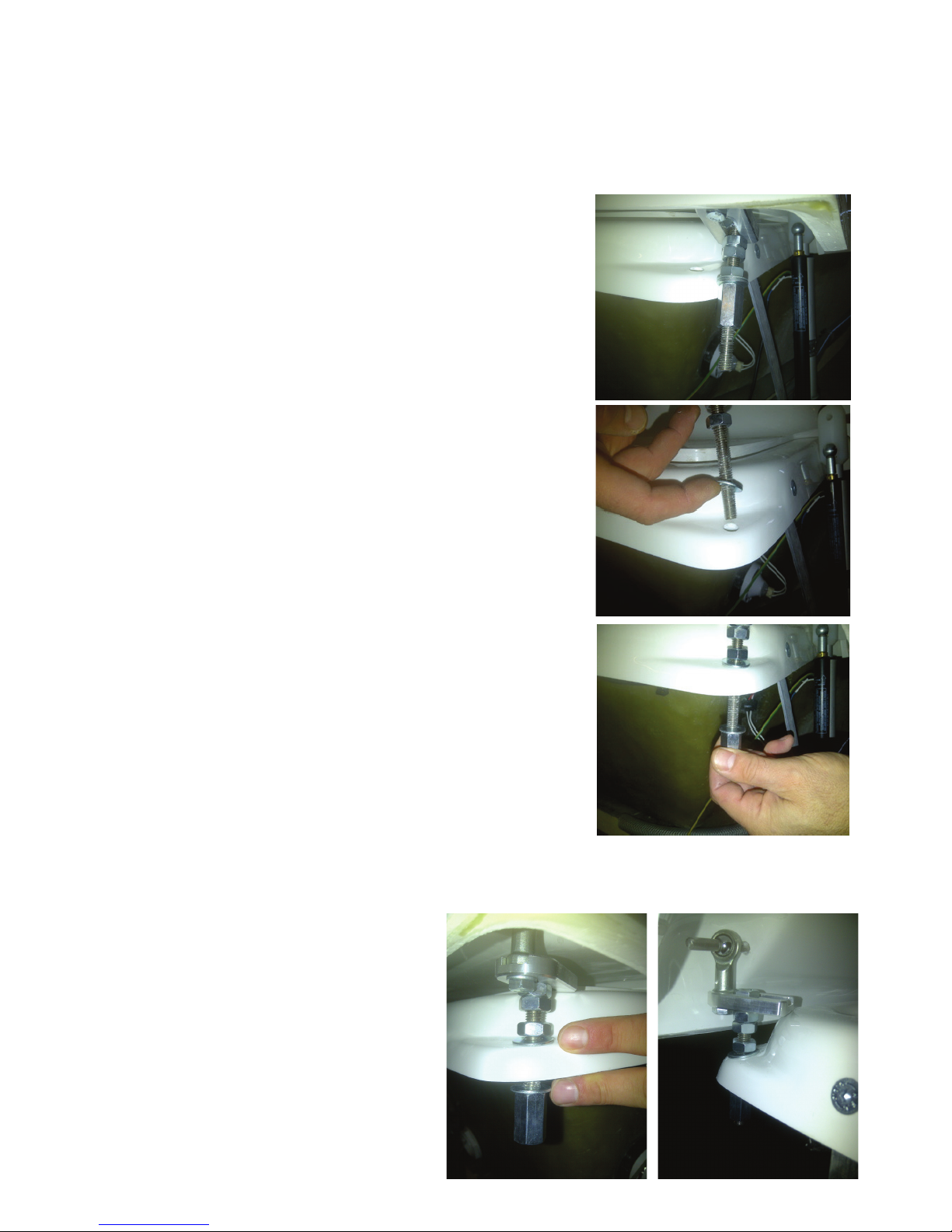
The door is held by two hinges which come tted to the door. They must be inserted into the pre-
drilled holes in the corners of the tub. This photo shows the hinge as it comes attached to the
door.
To t the hinges, on each side :
1. Remove the lower long M10 nut from the retaining bolt and
the bottom washer.
2. Lift one end of the door a little, so that the bolt can enter the
hole in the tub leaving the top washer to sit on top of the back
corner of the tub.
3. Add the washer underneath and the long nut and tighten by
hand.
4. Repeat on the other hinge.
5. Check the door opening manually.
6. Place a towel over the back of the dome to act as a spacer
and close the door.
7. The hinges can be fully adjusted. The nuts securing the
hinges to the tub are also used to adjust the height of the door.
The two adjacent nuts towards the top of the hinge are used to
adjust the door backwards and forwards.
8. After testing whether the door opens and closed correctly,
adjust if necessary, and fully tighten all the bolts using the two
17mm spanners provided in the accessories box. Check once
the control box is connected before you t the side panels.
9. Check that the hinges are well located on the 8mm pins of
the door and retained by spring “push on” retainers as shown
on the photo below right. These have been factory installed.
10. Recheck the door opening and remove the towel.
The photo on the right shows the installed
hinge in its correct position.
Page 9
9
Floataway Installation Manual 230v 50Hz Tranquility 2017 - v3
The Suction Assembly and Pump Connections
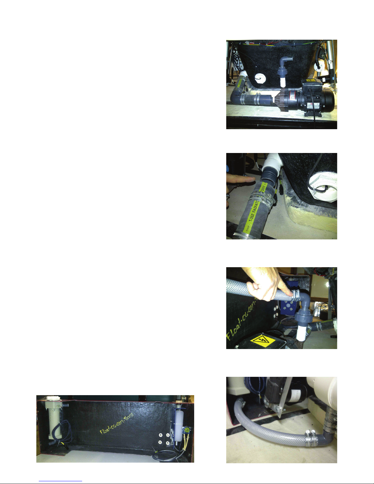
Carry in the pump and the suction hose and place it behind
the tub, leaving at least 10” behind the tub to the back wall.
The 1 1/2” black rubber hose forms the suction assembly
which connects the tank outlet to the pump. The tub tting
includes a plastic tube outlet and elbows
The photos show a 220v TE6 pump, depending on your
specication your pump may be different.
Fit the 1 1/2” rubber hose to the plastic tube and position
two hose clips as shown in the photo above right, pushing
the hose fully onto the pipe. Tighten the clips around the
hose using the hose clip driver (7mm) provided.
Check before connecting, that all the hose clips are aligned
so that they can be tightened easily and that they can be
easily reached in the future. When the water has heated
up, it is necessary to re-test the tension on these ttings
The Filter Connections and Back Panel
Bring in the back panel with its lter housing and autodosing unit already tted. Position it behind the tub.
You should leave at least 10” to the back wall for future
maintenance work.
Note: the lter inlet is at the top. The exit tube is at the
bottom of the lter housing. Connect the pump outlet to the
top of the lter, as shown in the photo on the right.
Then connect the hose from the UV lter (optional) to the
bottom of the lter housing as shown on the photo here :
Each tube connection has two clips for reliability.
Make sure all the pipe clips are tight.
Top
Page 10
10
Floataway Installation Manual 230v 50Hz Tranquility 2017 - v3
Water Isolation Check
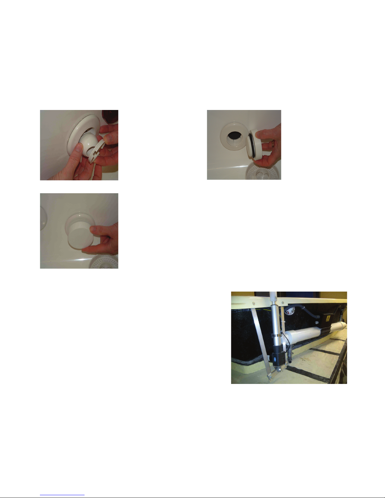
If servicing is required after installation (for example to change a pump), two threaded plugs are
tted to the back panel which can be screwed into the suction and water delivery ttings inside
the tank to shut off the water ow to the pipes and pump. The photos below show the pre-lter
removed behind the skimmer and the plug screwed into the pre-lter’s place.
The jet also unscrews, as shown in the photo, to allow one of the two plugs provided to be put in
its place to shut off the water supply when changing or servicing a pump.
Remove the ball of the
water jet by rotating the
retaining ring
Remove the
skimmer and
the pre lter
Once the jet tting and the pre lter are removed it is possible to
use the isolation bungs supplied, they simply screw into the tting
and hold the water in the tank; they do not need to be very tight.
This is useful if you need to work on the technical parts with water
in the pool.
The Jacks
The jacks (lift motors) open the door and are supplied
tted to the tub and to their brackets at the back of the
tank.
If you must remove the jacks, please note :
One has a longer cable to reach to the far side from the
control box, which is on the suction side of the tub.
Make sure the jack brackets are tight.
Page 11
11
Floataway Installation Manual 230v 50Hz Tranquility 2017 - v3
POOL
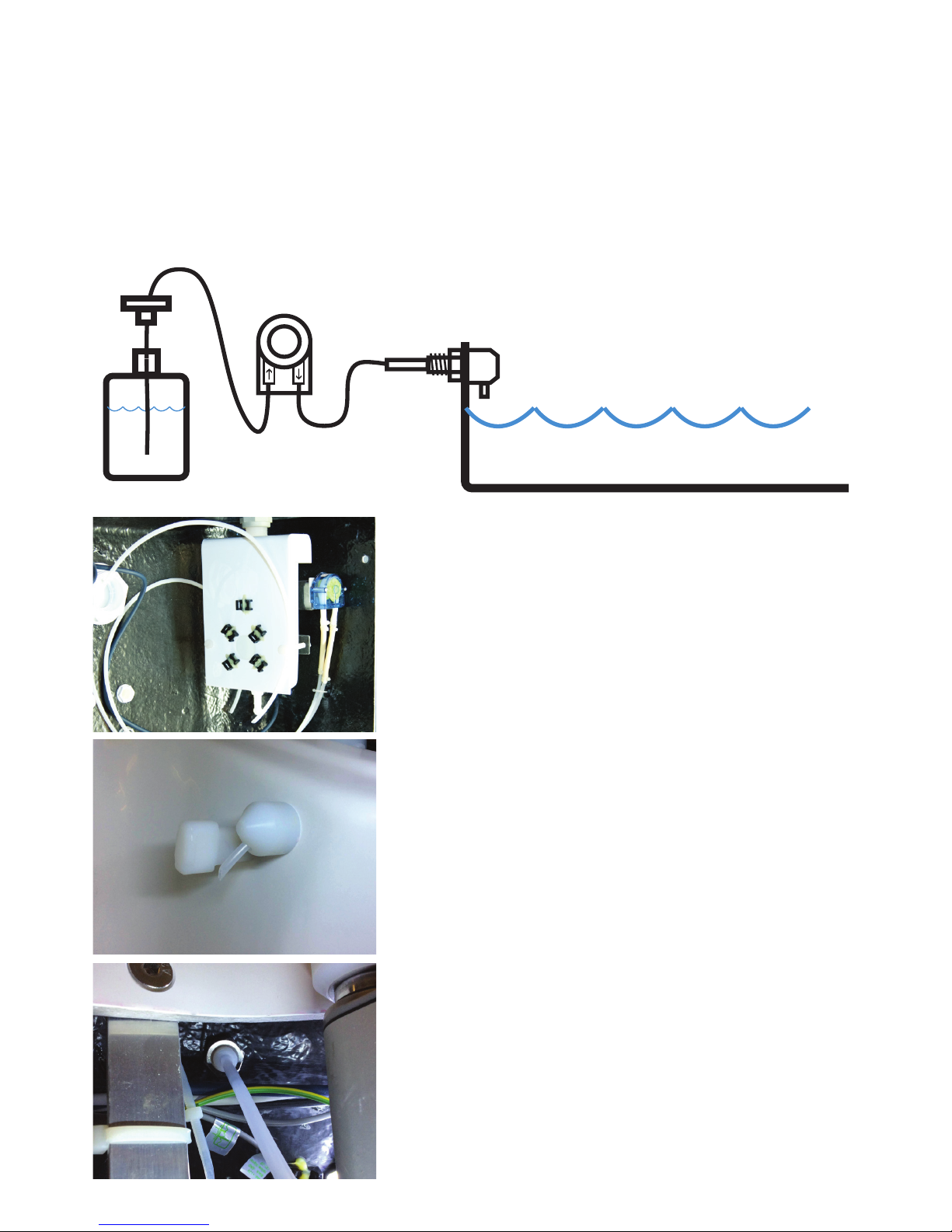
The Auto Doser - Liquid Disinfectant Upgrade Option.
The auto doser is a 12v system, the pump runs when the main water pump runs. The time is
controlled by the program and is adjustable. The liquid disinfectant is stored in the reservoir bottle
and pumped into the tank through the jet behind the weir.
Check the pipe has no bends or kinks. Use the soft rubber connection tubes to t the hose to the
jet hose - secure it with two zip ties. Fit the level sensor to the reservoir bottle in the same way as
the water level sensor.
The bottle and pump are tted at the back of the tank.
The reservoir bottle holds 1Lt. test the system for leaks
with 300ml of fresh water before adding chemicals.
Use gloves and eye protection when lling with disinfectant
The Jet into the tub is tted behind the weir, you can adjust
the length of the jet, it can be replaced also. Make sure the
liquid drips into the water and does not run down the side
of the berglass.
The hose should not dip into the water
The back of the jet is tted with an M14 nut, nger tight
only, do not use tools, if overtightened it can sheer off the
shaft of the jet.
Page 12
12
Floataway Installation Manual 230v 50Hz Tranquility 2017 - v3
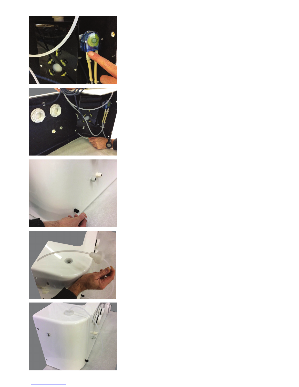
The Pump sucks the liquid from the reservoir and pushes
it into the tank, make sure the direction arrows are correct
when tting the hoses.
Thread the suction hose through the gland seen here.
Pull the hose out making sure not to kink during the
operation.
When the hose is threaded through the lid, it will look
like this. Make sure the hose reaches the bottom of the
reservoir.
The lling cap is removed and then use the funnel to
carefully ll the reservoir - do not overll. ll when empty by
adding 1Lt, do not ll to the brim.
It will look like this when nished.
Page 13
13
Floataway Installation Manual 230v 50Hz Tranquility 2017 - v3
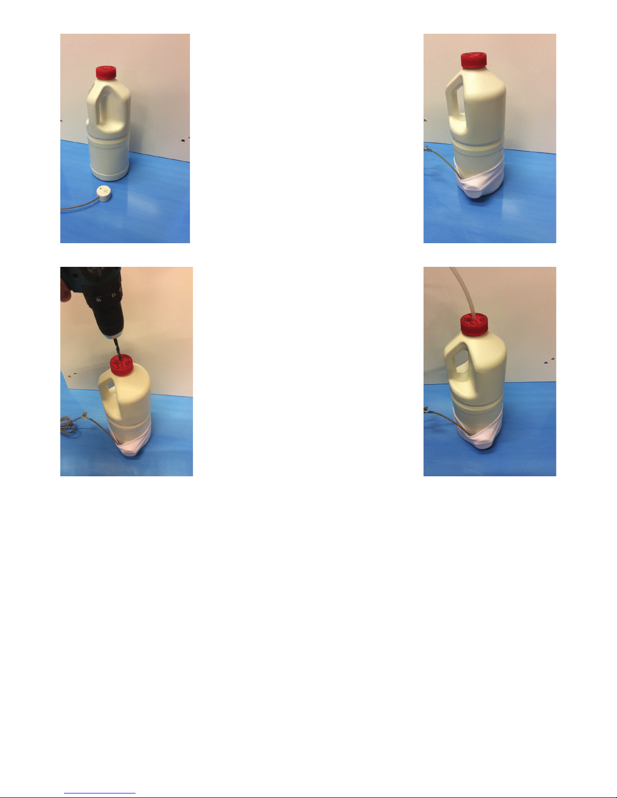
The Auto Doser -
Liquid Disinfectant:
Using a different
disinfectant bottle
- optional
There is a reservoir tted to the technical pack, but if you choose to use the
bottles your disinfectant is supplied in,
the level sensor can be strapped to the
bottle with the elastic strap.
If the bottle does not have a hole in the
lid, simply drill one to have access for
the pipe.
Page 14
14
Floataway Installation Manual 230v 50Hz Tranquility 2017 - v3
The Control Box and Connections
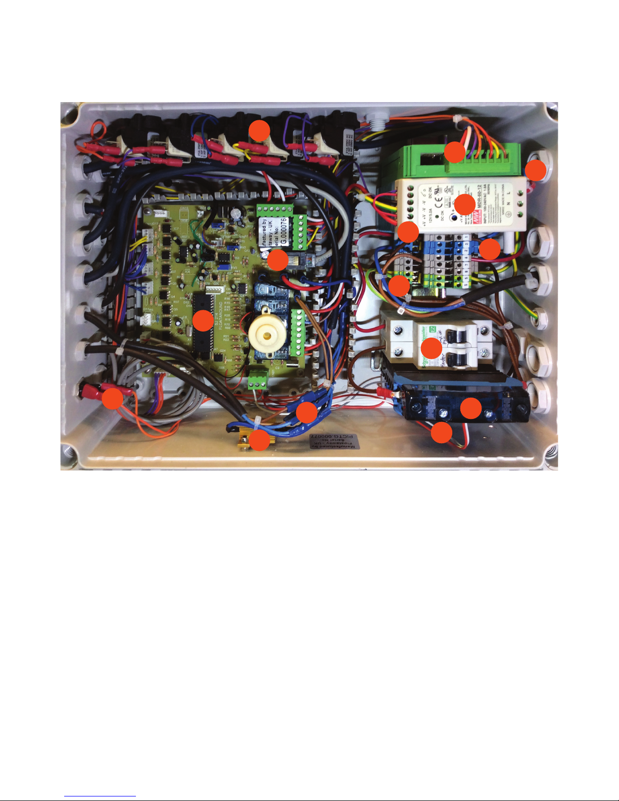
The Control Box
Description of the control box - Standard setup :
1. The mains or supply cable is at the top right on the photo above.
2. Solid State Relay (SSR) for the heaters.
3. Pump relay (obscured by SSR in this photo)
4. MCBs mains circuits
5. Earth / ground connectors
6. Supply N - 230v 50Hz 20A : N : Terminal 2
7. Supply L - 230v 50Hz 20A : L : Terminal 1
8. Control Power Supply 12v dc (adjusted to 13.5v with no load). (PSU)
9. Floataway fader Audio amplier.
10. Jack (motor door) load resistor
11. Jack (door motor) connectors - 12v
12. LAN type communication socket with a RJ45 plug
13. Air switches for air buttons on tank
14. Main control board
15. Under water Light fuse - 2A
2
3
4
6
7
5
8
9
10
1
11
12
13
14
15
Page 15
15
Floataway Installation Manual 230v 50Hz Tranquility 2017 - v3
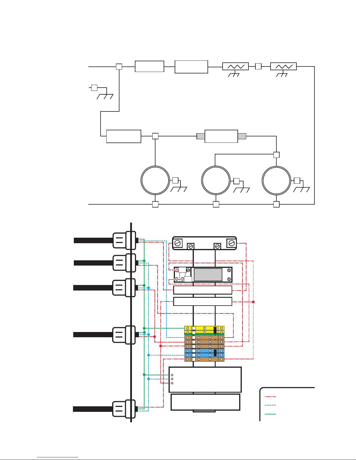
The Control Box Diagrams
PSU
UV
230v Supply N
230v Supply L
Heater Pair
Water
Heater SSR
SSR
Earth Supply
Pump
Water Heaters
MCB 2: 10A
Pump,PSU,UV
1
5
5
5
6
5
Relay 1
PUMP
11
14
7
2 2 2
8
MCB 1: 10A
Heater 1&2
Heater 2
Pump
SSR
Heater SSR Relay
Pump : Relay 1
230V
50Hz
12v Power Supply
Audio Amp
MCB 1: 10A Heater 1&2
MCB 2: 10A Pump,PSU,UV
Supply
230v AC 20A
Live
Neutral
Earth
(hot)
Heater 1
UV
6
5
5
7
2
2
1
8
Ground
PUMP
11
14
Supply
230v 50Hz 20A
Page 16

16
Floataway Installation Manual 230v 50Hz Tranquility 2017 - v3
The Electricity Cables
The pump and heaters must be connected to the control box.
Do not turn the tank on yet.
The Pump Cable
The pump cable must be fed through one of the cable glands and connected to:
Ground/Earth Terminal 5
Neutral Terminal 2
Switched live for the pump Terminal 7
The UV option (factory tted)
The UV ltration system turns on/off with the pump.
Ground/Earth Terminal 5
Neutral Terminal 2
Switched live for the Pump & UV Terminal 7
The Heater Cables
The heaters are 110V type wired in series pair (see diagram). Feed the 2 heater cables through
the zip ties along the tank towards the control box, and then into two glands and connect to:
Ground/Earth Terminal 5
Neutral Terminal 2
Switched live for the Heaters Heater MCB 1
Heater bridge connection Terminal 8*
*The two heaters are connected together in series - this is VERY important.
Visually check the connections, use a ohm meter to check that there is no short to earth. The
resistance from live to earth measured at the free end of the supply cord should be more than
1M ohm. Finally connect the main supply (which must be, as previously stated, via a GFCI and
isolating switch).
Do not switch the tank on until there is water in the tub and do not switch on if the bottom of the
tank (and therefore the heaters) is covered with Epsom salt which has not been fully dissolved.
Qty V. Hz. item total A. MCB MCB MCB Load Load use
W. W. A Type sub Total of circuit
Heater set 2 230 50 350 700 3 10 C - 3 30%
Pump 1 230 50 370 370 2.5 - -- 2.5 - 25%
PSU 1 230 50 198 198 1.8 - - 1.8 - 18%
UV 1 230 50 50 50 0.2 - - 0.2 - 2%
- - - - - - 10 C 4.5 45%
Supply 20A 1 230 50 - 1318 7.5 - - - - 38%
Page 17
17
Floataway Installation Manual 230v 50Hz Tranquility 2017 - v3
Connecting the wires
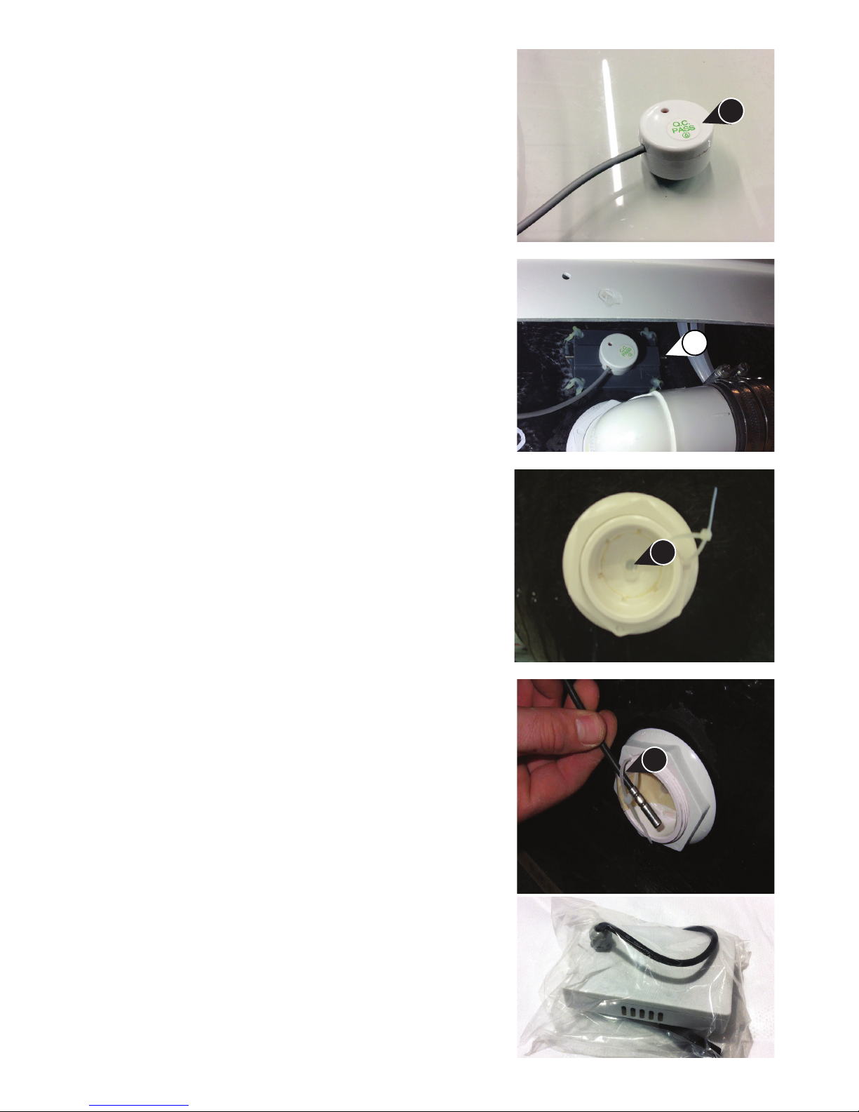
The water level sensor
The white water level sensor (WS) works by capacitance
and is tted on the outside of the panel behind the weir.
It is wired to the control box and must be put into position
and fastened with the tted grub screws (GS), it must be
tted with the red LED facing out. Do not overtighten the
retaining grub screws.
The water level sensor is positioned above the suction
outlet where it detects air when the water level is too low
for proper ow. Make sure the sensor touches the skin of
the tub. A small red sensor is lit when it detects water, it
should be illuminated all the time in normal operation.
The Temperature probe
This is a cable-mounted solid cylinder about 1/4” in
diameter. The temperature housing is pre-lled with
silicone grease. Pass the probe through the cable tie
(CT) and insert the metal tip all the way in to the hole
(TS). Tighten the cable tie around the wire (CT) to secure
it in its place.
The Back-up Battery
The back-up battery has a RED XLR lead. The battery
will maintain the lights and control functions during a
power cut. During the oat session, it will nish the
session as normal, when nished session, it wait roughly
20 min and will shut down completely, in standby it waits
20 min, then shuts down.
The battery is a 12v lead acid type, charged at 13.4v by
the power supply with a 10A fuse. Take care not to plug
the battery into any other connector!
End of Session Chime
The Interface panel has an end of session chime that
sounds when the oat session has come to the end.
WS
GS
TS
CT
Page 18
18
Floataway Installation Manual 230v 50Hz Tranquility 2017 - v3
The under water lights
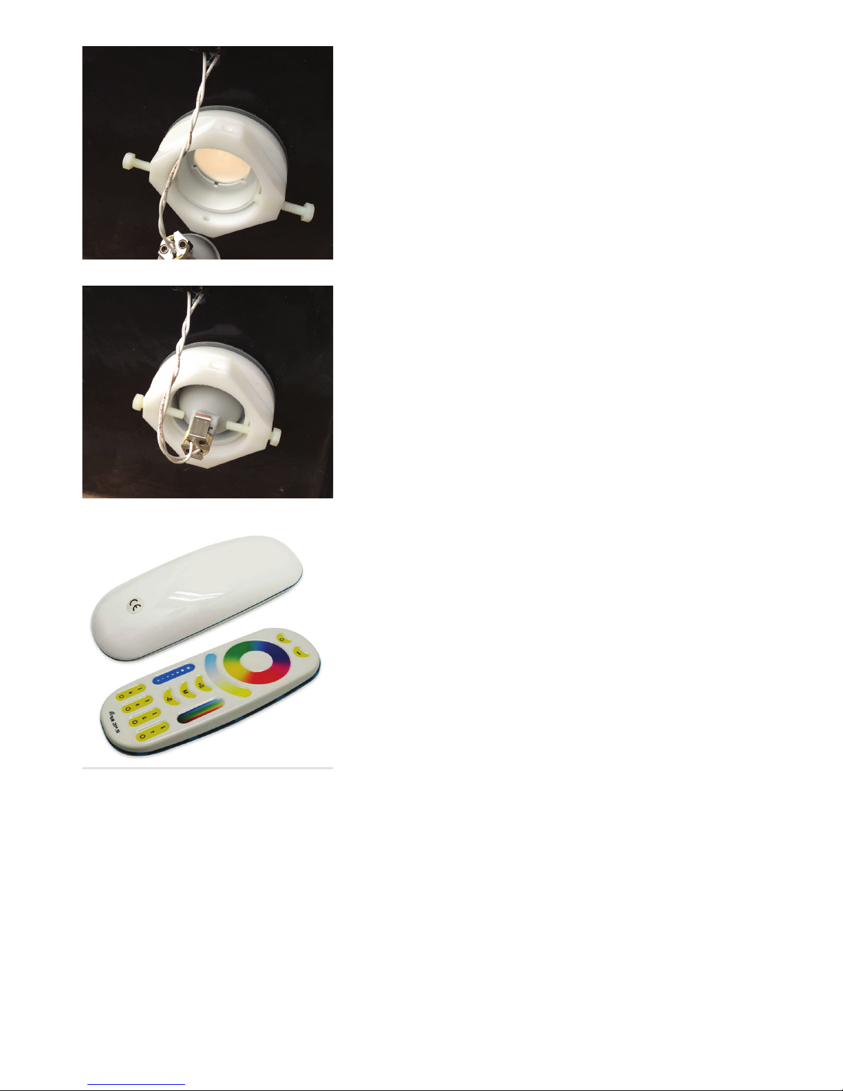
The under water light/s are a combination RGB, warm
white and cool white LED unit. The lamp has a 12v supply
and a remote control. The remote can adjust the colour and
brightness of each lamp individually or all at the same time.
Once the lamp colour and brightness has been adjusted to
your room. the lamp will keep those settings, turning on/off
with the oat session control, remembering the settings you
programmed.
The lamps are coded in the factory to your remote, each
lamp uses a different “zone” number. you can reprogram
these numbers if you choose.
To t, unscrew the two clamp bolts by hand.
Remove all packaging and carefully position the lamp into
the lamp housing. You are now ready to re-t the lamp
Carefully slide the lamp into the holder and re-tighten the
two bolts by hand to secure the lamp.
The remote for the lamps uses 2.4G Wi-Fi, it needs to be in
range to control the lamps, the lamps can only be adjusted
when they are ON.
To adjust ALL the lamps at once, use the O/I buttons above
the colour wheel to turn the lamps off/on then adjust the
colour/brightness of the lamps together.
To adjust individual lamps, press one of the “1-4 zone” O/I
button at the bottom of the remote, then adjust the colour/
brightness of that lamp.
To adjust the the colour/white balance use the RGB slider
To adjust the the brightness use the brightness slider
To adjust the the warm/cool white balance use the blue/
yellow slider
To select the Mode to have multi colour fade sequence
etc, use the M button, and then adjust the speed with +/-
buttons.
To LINK a lamp to a zone : turn lamp OFF, and then ON,
press chosen Zone button 3 times within 10 sec.
To UN-LINK a lamp to a zone : turn lamp OFF, and then
ON, press corresponding Zone button 5 times within 10
sec.
Page 19
19
Floataway Installation Manual 230v 50Hz Tranquility 2017 - v3
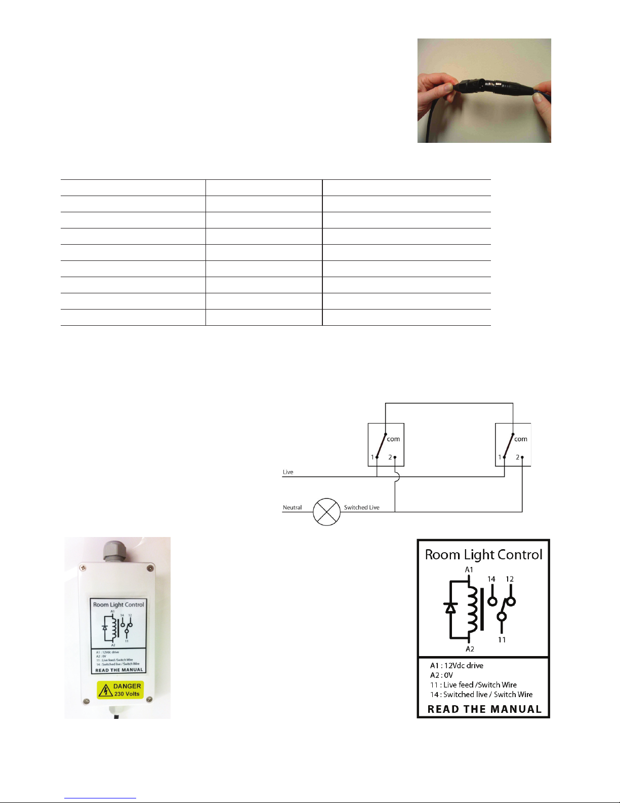
The XLR connectors
This photo shows an XLR connector. Depending on which optional
extras you have ordered, there are a number of these coming out
of the control box. Each is colour coded and must be connected to
it’s other half. The male XLR is connected to the tub and the female
XLR is attached to the control box. They simply clip into each other
as shown in the photo on the left.
The XLR connectors
Item Power Colour Code
Lights 12v pulsed 1A max White
Bing-bong sounder 12v pulsed Blue/White
Loudspeaker Audio speakers Green
Back-up battery 12v constant Red
Auto-Doser 12v pulsed Green/Yellow
Filter Sensor 12v switch Yellow
Colour Therapy 12v constant Red/White
Intercom 12v constant Red/White
The Room Light Control
Optional room light control is tted
in a separate box next to the main
control box. This is to keep separate
mains power circuits isolated for safety.
Remember this box may still be live even
when the main power to the oat pool
has been switched off as the supply may
be from a separate lighting circuit.
Use a qualied electrician to connect
up the room light control. It can be used
as part of a standard two-way switching
circuit as seen above.
Page 20
20
Floataway Installation Manual 230v 50Hz Tranquility 2017 - v3
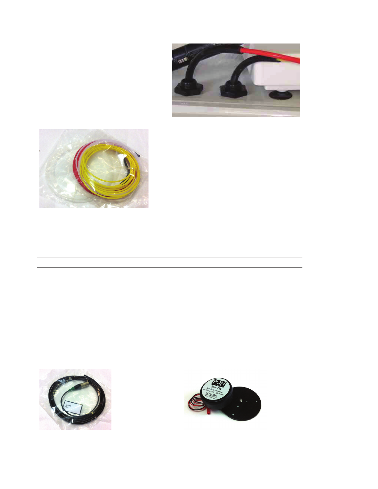
The Air hoses
The switches in the pool area are
connected by 4mm air hoses, these need
to be connected to the air switches on
the side of the control box.
You simply need to push the black tip
over the small nipple as shown.
Enough tubing has been provided, you
should not need to cut it.
Application Air Button Colour Air Line Colour
Light Button White Yellow
Call Attendant Button Red Red
Music Mute Black Clear/White
Inner Door Black Blue
Outer Door Black Green
The Music/Speaker
The sound is transmitted into the water with a sound transducer that excites the surface of the
technical pack. The wire has been provided to connect to this, it uses an XLR connector with a
GREEN colour code. It is a mono system (one sound source) as stereo does not work underwater
due to the speed of sound in water is different to air. The control box has an amplier built into it,
the sound source is at the remote through a 3.5mm standard headphone socket.
Music Mute is built into the amplier, there is an additional air button if tted.
The cable is tted
to the side of the
tranquility in the
factory
The sound
transducer is tted
to the side wall of
the tank near the
head area.
Page 21
21
Floataway Installation Manual 230v 50Hz Tranquility 2017 - v3
The Intercom system
The intercom is a 12v system, it gets the 12v from the control box at the tank. There is a volume
adjustment at each end of the system. The amp at the tank sends the sound to the handset. The
amp in the handset send the sound to the tank.
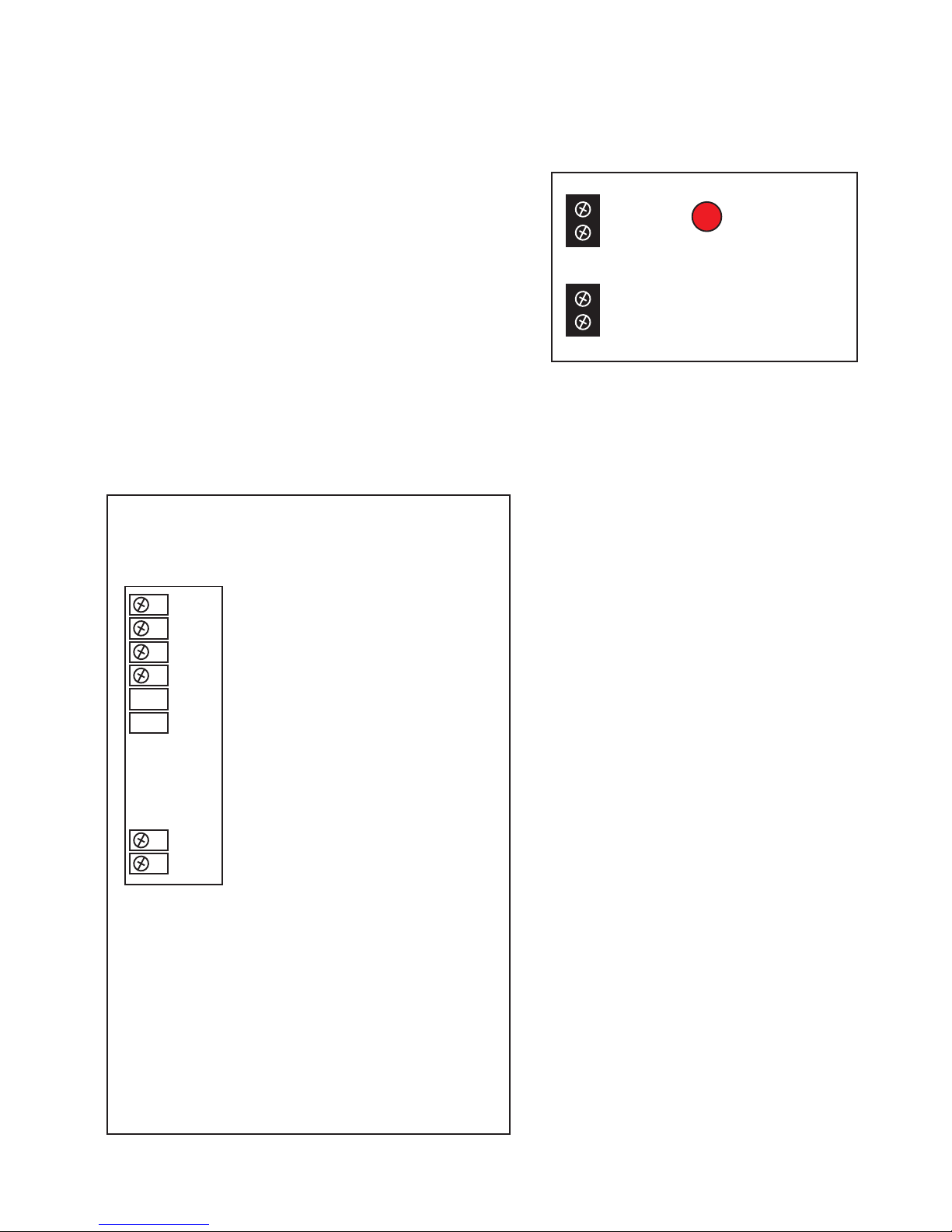
To adjust the volume, open the case
and adjust the red dial seen here
The intercom is wired to LAN cable with RJ45 pugs, a
separate cable must be used for the intercom, it must
not go through any other units/routers etc. The LAN
cable pairs are wired together
The mic at the tank is connected via a clear tube.
To use the intercom, lift the handset, when lifted you can hear the customer in the tank, press the
talk button to talk. When pressing the talk button you will not be able to hear the client, the sound
goes one way at a time. This is because feedback in the tank is very bad and having a press to
talk system eliminates feedback issues.
1 : Voice signal from tank to handset : Blue
2 : Voice signal from handset to tank : Green
12v + : 12v+ via LAN - intercom box at tank : Brown
GND : 0v via LAN - intercom box at tank : Orange
: not used
: not used
: not used
: not used
Back of intercom
Volume
Adjustment
Page 22
22
Floataway Installation Manual 230v 50Hz Tranquility 2017 - v3
Music system
The system includes an amplier with automatic fader, this is controlled by the oat session
settings. For this to work, you need to connect a sound source that plays music continuously, the
control box will then fade the music up/down as the oat session progresses.
Music must be provided from a music source such as an MP3 player, CD player or computer.
Floataway does not provide the music source.
Warning
The Floataway system uses the headphone level output (one volt peak) which is always a 3.5mm
stereo jack socket on typical equipment. No other music level (voltage) can be used, speaker
output/high level will destroy the built in amplier and risk damaging the control box itself.
Connection
Connect the music source to the oat pool by using the provided cable with 3.5mm stereo
jacks. One end plugs into the remote control at the right hand side, the other end plugs into the
headphone socket of your source. The operator must ensure that music is playing on the music
source for it to work in the oat Float Pool.
The system provides automatic fading (down) of the music after a few minutes into the session,
with fade back up towards the end of the session. The music can also be on or off all the time.
This can be changed per session AFTER starting the session. (using the adjust button, see earlier
notes)
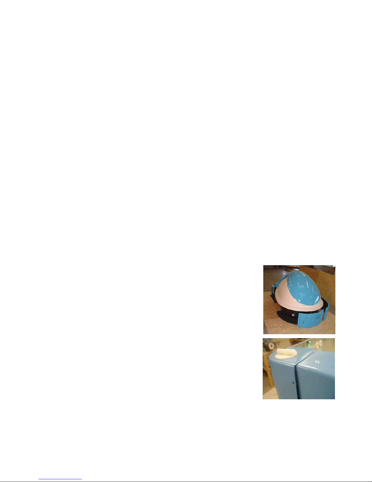
Fitting The Side Panels
Carry in the remaining 3 panels and t the back ends of each of the
long side panels under the back of the back panels as shown in the
photo below. The panels are supplied with M8 bolts in place. Unscrew
the bolts using the 13mm socket driver provided and position the side
panels so that the drilled holes match up. Put the M8 bolts in the back
panels before doing the front panel.
Always t the nylon M8 bolts by hand, to avoid cross threading, then
use the nut driver to tighten them.
Remember to connect the external door switch air hose, i.e. the green
air hose.
If the ground noise isolation system is tted, make sure no part of the
side panels are touching the tub or workings.
Page 23
23
Floataway Installation Manual 230v 50Hz Tranquility 2017 - v3
A
C
DF E
H
wall
socket
reception
cable from control
box to wall socket
cable from remote
to wall socket
Remote
Control Box
G
3.5mm audio
jack lead
Sound source
MP3 / PC?
i
control board
green amp
tracks/jumpers on the board
wires between the baords
Float room Reception Area
CAT5
CAT5
CAT5
wires between the connector and board
B
JW1
TK1
W3
TK2
tracks/jumpers on the board
A
C
F
H
F-F
Adaptor
reception
cable from control
box to wall socket
cable from remote
to wall socket
Remote
Control Box
G
3.5mm audio
jack lead
Sound source
MP3 / PC?
i
control board
green amp
tracks/jumpers on the board
wires between the baords
Float room Reception Area
CAT5
CAT5
CAT5
wires between the connector and board
B
JW1
TK1
W3
TK2
tracks/jumpers on the board
A1
A2
KL
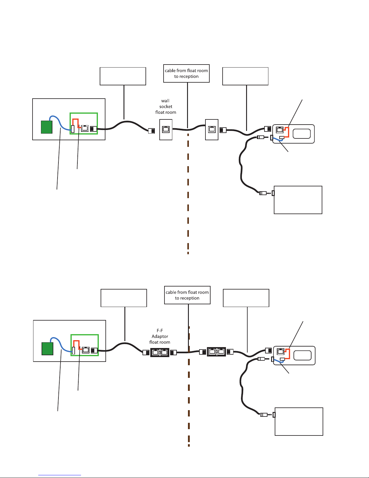
Identifying parts of the LAN and Audio cables
Standard setup using F-F adaptors
Standard setup using LAN wall plates
Page 24
24
Floataway Installation Manual 230v 50Hz Tranquility 2017 - v3
The Remote Control
The remote control can and should be tested connected directly to the control box before
connection to the installed LAN cable.
The wiring for the LAN cable and any connectors used must be pin for pin, never the mirrored/
cross over type.
There is also a separate quick guide document on the operation of the remote
WARNING
Reversing the wires will (unlike a normal LAN cable)
cause permanent damage to the controller and remote
circuits! We strongly recommend that the installed LAN
cable with its connectors is tested with a appropriate
LAN tester before connection of our equipment.
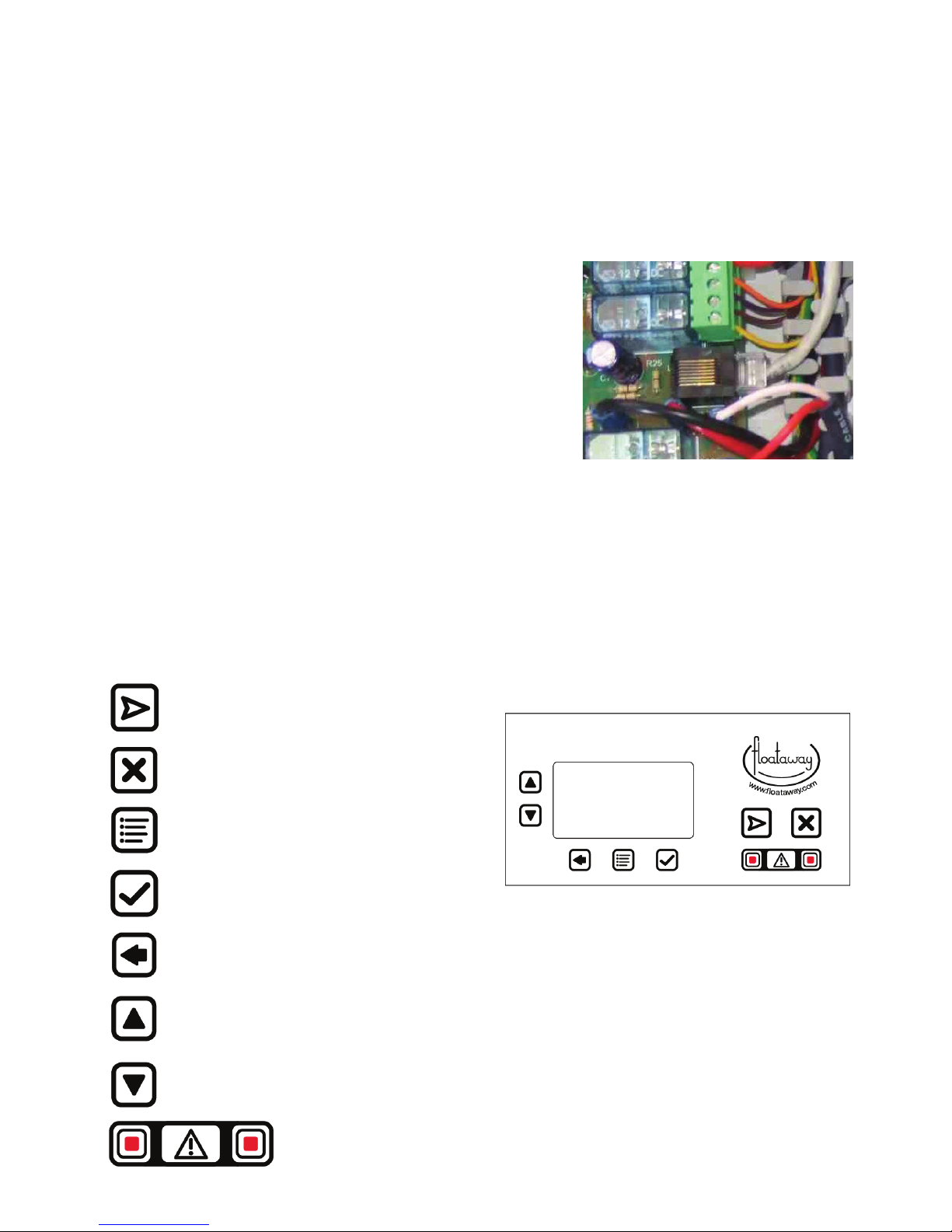
The LAN cable connection is inside the control box on the
mother board as shown in this photo.
After testing, and with the power off, disconnect the remote
control LAN RJ45 plug from the control box and install the
remote box at its nal position.
Connect the remote to the previously installed LAN cable. This may be either by male to female
RJ45, or by male to male with a double ended female RJ45, or even by hard wired LAN junction
box. The control box connection does require a cable mounted male RJ45 plug to be plugged in
to the socket from where the remote was disconnected.
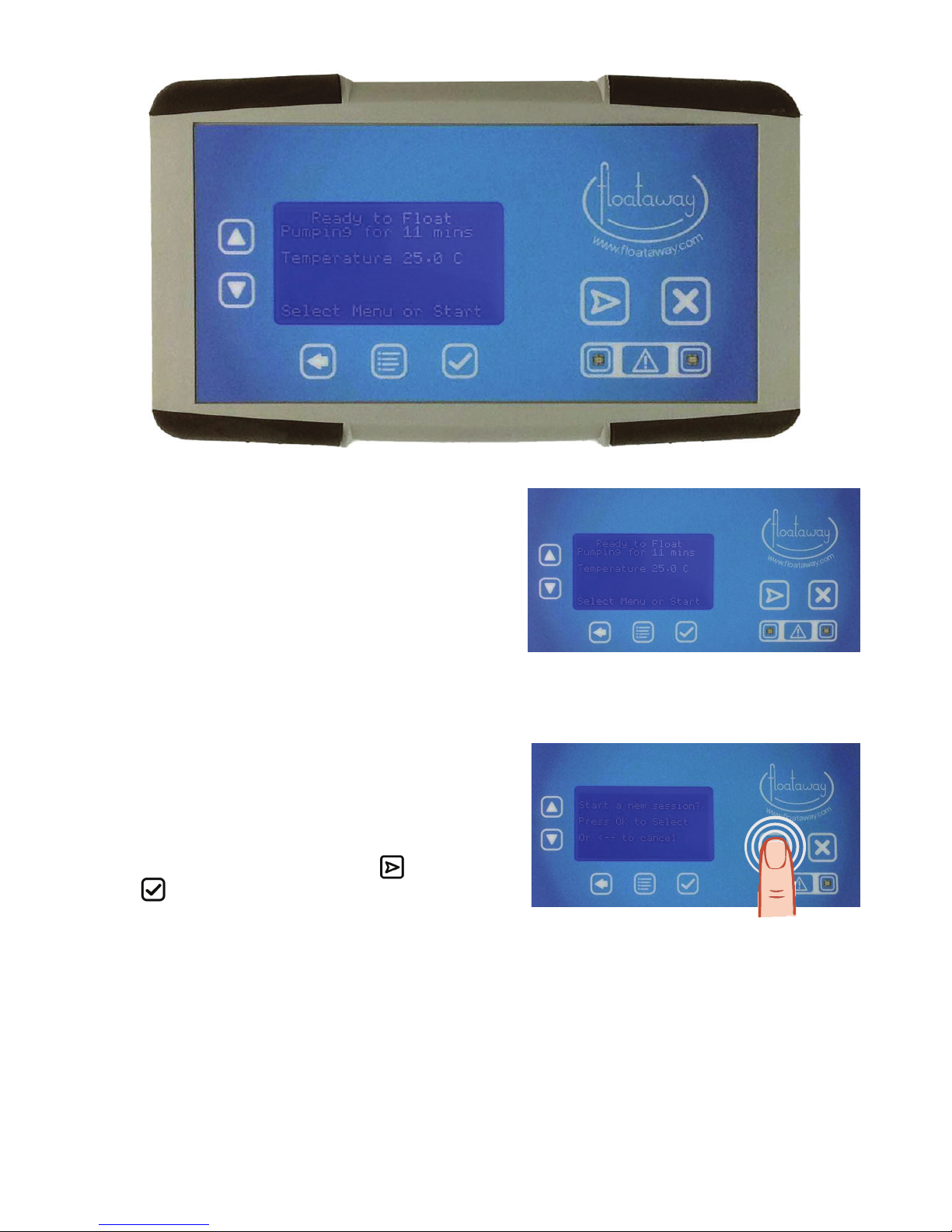
The remote control also has a socket for sound.
Start a new Float Session
Stop the running Float Session
Menu
OK (yes)
Back (cancel) - if in settings, save y/n is asked on using this button
Up / Down to navigate
the menu items
The Alarms are signaled by ashing red lights and an audible
buzzer, the cancel button in the middle.
Page 25
25
Floataway Installation Manual 230v 50Hz Tranquility 2017 - v3
Using the Remote Control
The Floataway remote control allows you to start
automated sessions and to change parameters such
as temperature, session length, music fade, and pump
times.
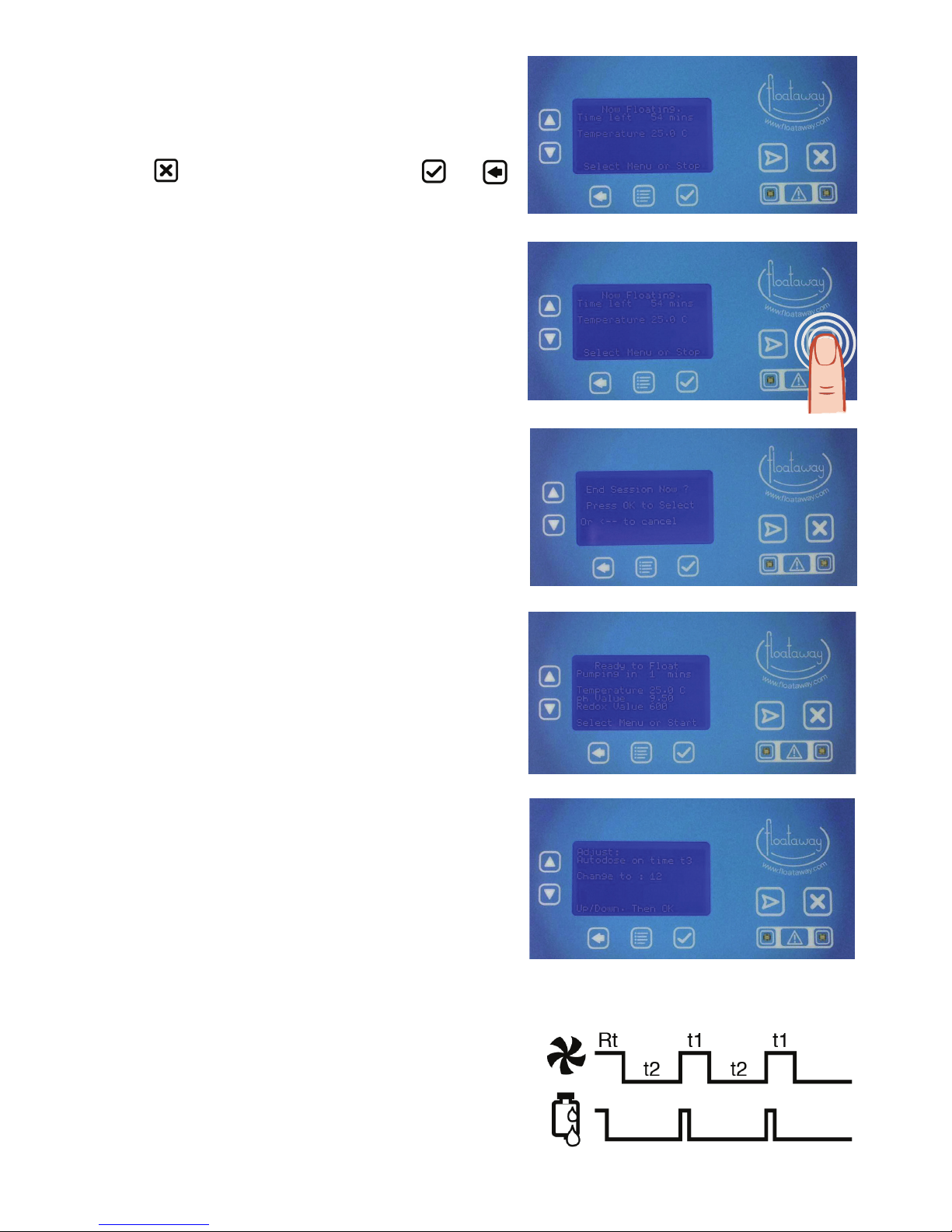
This is the screen you normally see between
sessions.
The time to the next pump start, or the time to the next
pump pause is shown, as is the temperature.
Very often, the only action required is to start a
new session.
To start a new session press START
and then
press .
The session will then be timed automatically with the
music fade, “bing-bong” sounder, light, door opening
and pump start, all automatic, depends on the model
and options selected.
At the start of the session, in the case of the
Tranquility pod, the motorized door will open and wait
for the customer, who will close the door when he or
she is ready.
Page 26
26
Floataway Installation Manual 230v 50Hz Tranquility 2017 - v3
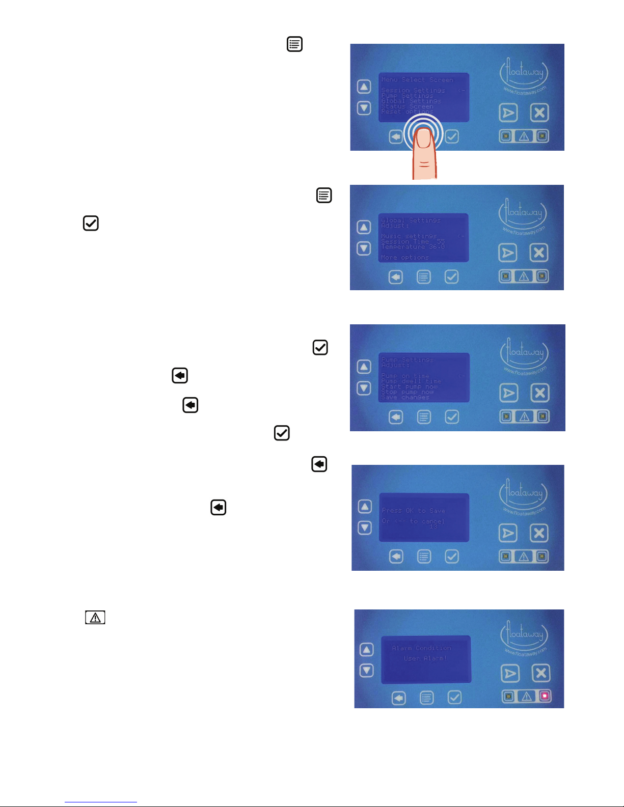
The screen will change to say : “Now Floating” and
will remain in this state, counting down the minutes
until the automatic end of the session.
If you do want to end the session for some reason,
use the
button on the right, then press , or
to cancel and carry on with the oat session.
Ending the session is a sequence including the music
fading up, lights and in the case of the Tranquility the
door opening.
Flashing Display
If the electricity supply fails, the display will ash. The
message will be “mains failure”.
The back up battery maintains the control of the door,
the lights and the call attendant buttons but there
is no heat or pumping during a power cut (outage).
The battery turns off after the end of the session to
preserve its life.
REDOX and pH
(These are options which only show if tted)
The redox (ORP) reading / pH value are displayed.
Otherwise the dosing may be manual or automatically
timed. The automatic dose times are found in the
menu. There are two times called t3 and t4. T4 is the
time in seconds for dosing after every session.
T3 is the time in seconds for dosing thereafter, each
time the pump runs. Usually this will be less, for
example, half of the t4 value.
The ‘ready to oat’ message scrolls to show the
temperature and other messages.
To make changes, press the menu button which is the
bottom middle button under the display. The refresh
time is not adjustable, this is a recommended time.
RT After oat session pump Refresh Time : 20min
T1 Pump run time in standby
T2 Pump dwell/off time in standby
T3 Auto doser run time during standby with pump
T4 Auto doser run time refresh after oat session.
t4 t3 t3
Page 27
27
Floataway Installation Manual 230v 50Hz Tranquility 2017 - v3
To adjust settings go into the Menu screens
Use the up and down arrow buttons on the left to
select from session settings, pump settings, global
settings or the status screen.
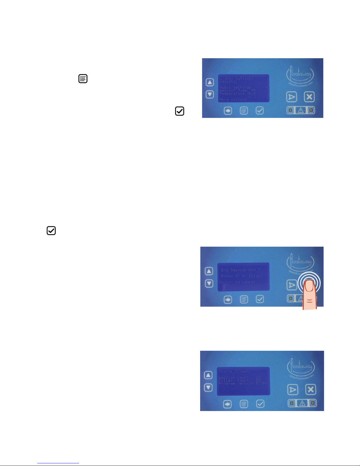
Float session Settings :
Session settings : for the current or next session.
Global settings : For changes to affect every session.
Parameters can then be adjusted. Use the menu
button and scroll to global settings; to save, press the
tick
button.
The Pump settings menu lets you change the on time
and the dwell time (the length of time the pump does
not run between pumping).
You can also start or stop the pump immediately.
Use the up and down arrows to move the indicator
arrow to the item you want, then select using the
then adjust. You can cancel or return to the last screen
at any time using the button.
You must use the back
button below the display
to exit the menu. The screen asks if you want to save
these changes, as shown above, use the
button
to save (the display counts up to 20 while saving), or
to cancel without saving your changes press the
again
You may have to press back
more than once
depending how deep into the menu you have gone.
You can also change parameters just for the current
session as above; these changes are not stored for
use again.
The button is only used for cancelling warnings
and is lit when buzzing.
This occurs if the customer presses the red ‘call
attendant’ button inside the oat pool. A unique
warning appears with ashing red lights and a buzzer.
The buzzer can be cancelled by pressing the triangle
centre button until it clears. A brief press will only stop
the buzzer.
Page 28
28
Floataway Installation Manual 230v 50Hz Tranquility 2017 - v3
Other possible alarms are for over high temperature
and low water. You will see the ashing lights but no
sound. These will not cancel until corrected. There
are further messages for low reservoir and some other
options.
Music Settings :
Use the menu
button; scroll to global settings, then
to music.
There are three choices : on, off or fade. Use the up
and down buttons to select, and then press OK .
On The music will play continuously
throughout the session, but stops at the end
of the session provided that the music source is
continuous.
Fade The music will start with the session and fades
down to silence after the programmed number
of minutes. At the end of the session the music
will fade up again two minutes before the end.
Off The Music is off, but will fade in at the end of
the oat session to indicate the end.
Now you must use the back button to exit the menu
and you are prompted to save the change, so press
OK
again.
End of Float Session
When the session stops either automatically or when
you press the end session button, there is a sequence
of events:
First, the music fades up (if it was off/faded)
Then the light comes on
After two minutes the door opens (Tranquility only)
Then there is the “bing bong” sounder to indicate
the end of session.
Finally, after another two minutes, the pump will
start.
The status screen above tells you the current session
count and also the number of sessions since last time
the lter was changed. Actually this is since the lter
top was last opened, but usually that is to change a
lter. The total session count is non-reset
and is intended to keep a record for audit purposes.
Page 29
29
Floataway Installation Manual 230v 50Hz Tranquility 2017 - v3
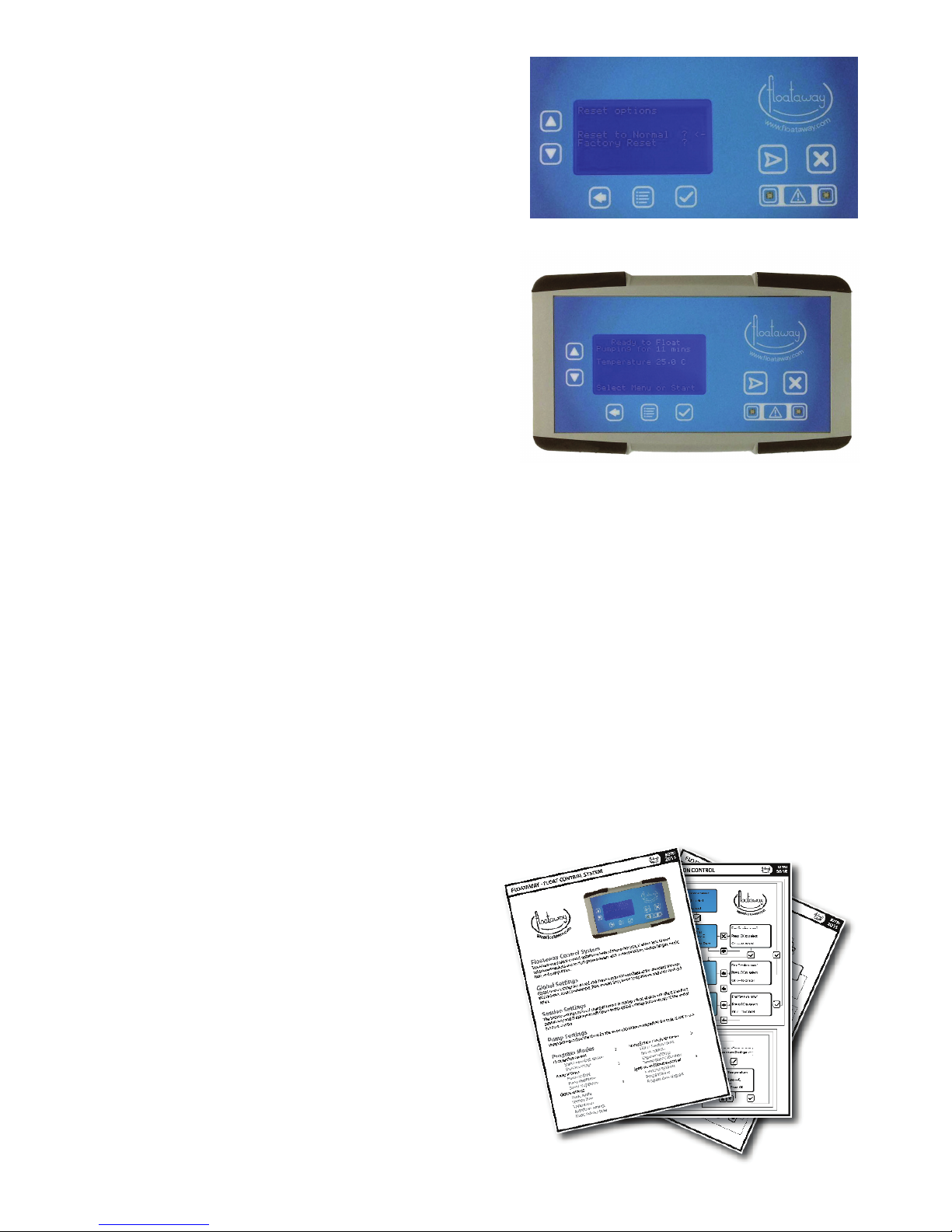
The Reset Option
We recommend that you do not use reset options
unless required, you may have to change all your
parameters from scratch.
Sound Source
There is a 3.5mm standard headphone socket on the
side of the remote unit near the Floataway Logo.
This is used to introduce music or speech from any
device with a headphone output, for example, a CD or
MP3 player, computer or iPod.
Recommended Values
Temperature 35.4 degrees C.
T1 15 minutes (the pump run time)
T2 60 Minutes (the pump dwell or off time)
T3 6 seconds (if tted)
T4 12 seconds (if tted)
If the automatic dosing unit has been ordered, there
also is a reservoir empty warning message.
There is also a separate quick guide
document on the operation of the
remote
There is also instructions for temperature
calibration in the quick guide
Page 30

30
Floataway Installation Manual 230v 50Hz Tranquility 2017 - v3
Filling the Float Pool with Water and Salt
Make sure your happy with the tank position before you add water and salt.
We highly recommend you ll the tank through a reverse osmosis unit.
The water and salt : You can add water and salt together, or all the salt rst, or the water to about
19cm (7.5”) deep and then the salt, but whichever way you, must stir all the salt until it completely
dissolves before turning on the heaters and pump. Add 300 kg of salt (12 bags, we supply one
spare in case of breakage) and bring the water up to a depth of 25cm (10”). The correct water
level is 1cm (3/8th of an inch) above the bottom slot on the weir.
Filling with Hot Water
Half the water can be put in rst, or the salt rst, depending on your water supply.
If enough hot water is available, put the salt in rst then ll to full depth, 27.5cm. It is preferable to
use very hot water as the salt cools the water as it dissolves.
Filling with Cold Water
If the ll water is cold we recommend lling to two thirds full, depth 18cm (7.5”). Do not ll the pool
completely (27.5cm) as this will be too much water after you’ve added your salt.
Turn on the heater and pump to warm the water to 37 degrees before adding the salt. To do this
turn on the power to the system. Using the remote control adjust function, set the pump time (t1)
to a maximum and the dwell time (t2) to minimum. The water will only heat while the pump is
running.
Only add the salt once the water has heated up and you have stopped the pump.
Mixing the salt to dissolve it in cold water is possible but takes a long time and can be unpleasant
for the feet. When the water is warm, turn off the Float Pool, add all the salt and mix.
Warning
Once the salt is put in the pool, it MUST be mixed by getting in and stirring with your
feet until all the salt is dissolved. Do not start the pump until all the salt is completely
dissolved.
To run the pump with salt on the bottom can cause permanent damage to the pump.
Floataway recommend the mixing of the salt to be done with the Float Pool turned off.
Continue to run the pump to heat the water until it reaches approximately 35.5 degrees C which is
the set point. Once it has reached this temperature, the oat pool is ready to be used.
Use the water chemical treatment supplied as necessary to correct the PH, and Total Alkalinity
Finally, check all the water connections for leaks and tighten if necessary.
Do this again after 24 hours of operation when the Float Pool should be at operating
temperature. THIS IS VERY IMPORTANT TO AVOID LEAKS!
All questions: please email to info@oataway.com for fastest response.
Page 31

31
Floataway Installation Manual 230v 50Hz Tranquility 2017 - v3
Troubleshooting Common Problems
Pump Problems
Do not run the pump dry.
Check that the lter top is closed, there is a magnetic switch interlock in series with the pump relay
drive. (This often is the cause during installation). Similarly check that the lter top detector is
connected.
If the water is low or the water level sensor not adjusted, the pump will run for a second and stop
and the alarm will sound. When the level is correct, the level sensor light on the sensor itself
should be lit.
Check the electrical connection and fuse.
If the pump makes a rattling sound, this is usually due to air being trapped in the pump. Turn the
pump off and open the lter top to release air.
If this rattle persists, or if the pump is stalled, it will be necessary to plug the suction with the
supplied threaded plugs (located in the back of the back panel), and dismantle the pump to check
the rotor.
If the pump runs but the ow rate is low, open the door and remove the lter cartridge, re-close the
lter housing with no cartridge and retest. Sometimes a cartridge can be blocked with oils but still
look clean. This is also a good way to clear air from the system after servicing a pump.
The silent pump option has a low ow rate.
Heating
When the temperature is lower than the set point the heater is turned on.
Note the heaters will warm slowly to the touch, taking at least 30 seconds.
The main supply can be checked with a mains tester screwdriver at the heat relay.
The most likely cause of temperature drop is a power cut, or the RCD (GFCI) has tripped out.
There is a mains fail detection circuit which causes a ashing signal at remote.
High Temperature Alarm
The common reason especially when newly installed, is when the tank is left overnight without
pumping. If the salt is not completely dissolved or mixed (which is easy to do by insufcient
stirring), then a salty dense layer forms on the bottom and can heat up to a high temperature, even
to 60°C (140° F). When next stirred by the pump, this layer can cause a general rise above the
alarm point. When the salt is completely mixed, this effect disappears but can recur when more
salt is added.
If the tank is left in pump mode, the regular pumping will prevent this effect by mixing the salty
layer.
Page 32

32
Floataway Installation Manual 230v 50Hz Tranquility 2017 - v3
Other Problems / Advice - Contact Floataway
There is also a separate quick guide document on
the operation of the remote:
Floataway is a registered trademark of Cosine Limited.
8 Ironside Way, Hingham Business Park, Hingham, Norfolk, NR9 4LF, UK
Ofce +44 1953 851 515 Factory +44 1953 851 861
Info@oataway.com www.oataway.com
Page 33
33
Floataway Installation Manual 230v 50Hz Tranquility 2017 - v3
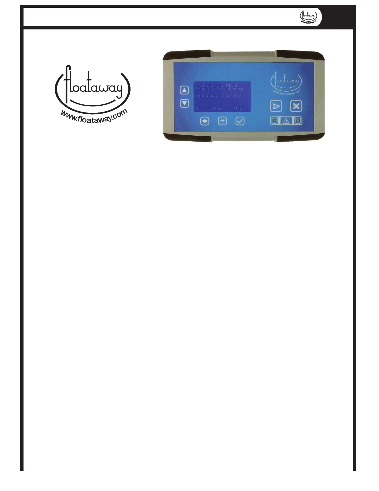
FLOATAWAY - FLOAT CONTROL SYSTEM
2015
B27RJ
Floataway Control System
The Floataway unique control system has been designed for you, it allows you to start
automated sessions and to change parameters such as temperature, session length, music
fade, and pump times.
Global Settings
Global menu settings are stored and the program will use these as the standard settings,
this includes, music preferences, oat session time, water temperature and auto dosing if
tted.
Session Settings
The Session settings menu, if changed before or during a oat session will eect that oat
session only and the program will return to the global settings automatically at the end of
the oat session
Pump Settings
Pump settings adjust the times for the water circulation pump when the tank is not in use
Program Modes
Float session control 2
Start a new oat session
Session settings
Pump settings 3
Pump on time
Pump dwell time
Start / Stop pump
Global settings 4
Music mode
Session time
Temperature
Autodoser settings
Music fadeout time
Status Screen / Engineer menu 5
Filter / Session count
Resest options
Engenier settings
Temperature calibration
Symbols and times explained 6
Icons and symbols
Program times
Program time diagram
Page 34
34
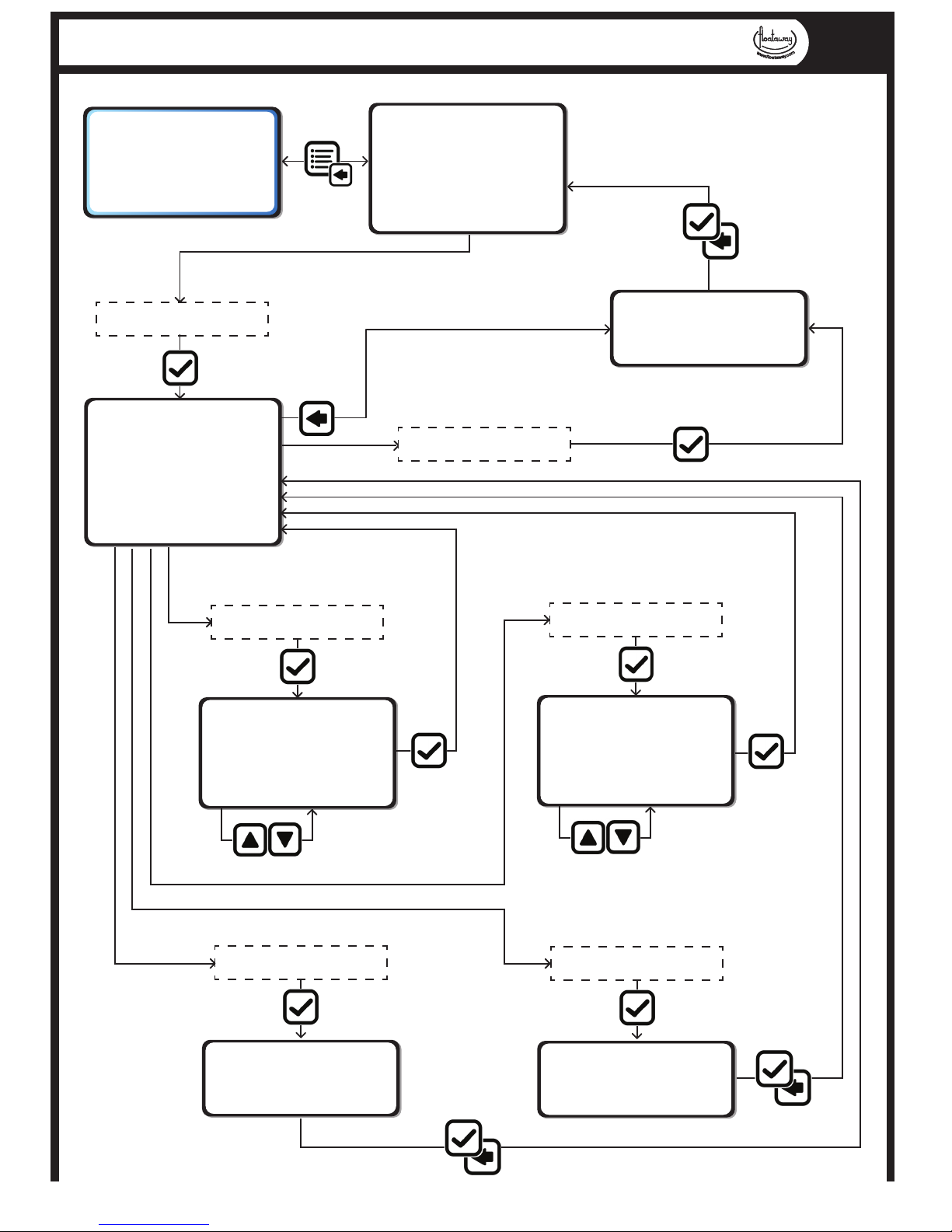
Floataway Installation Manual 230v 50Hz Tranquility 2017 - v3
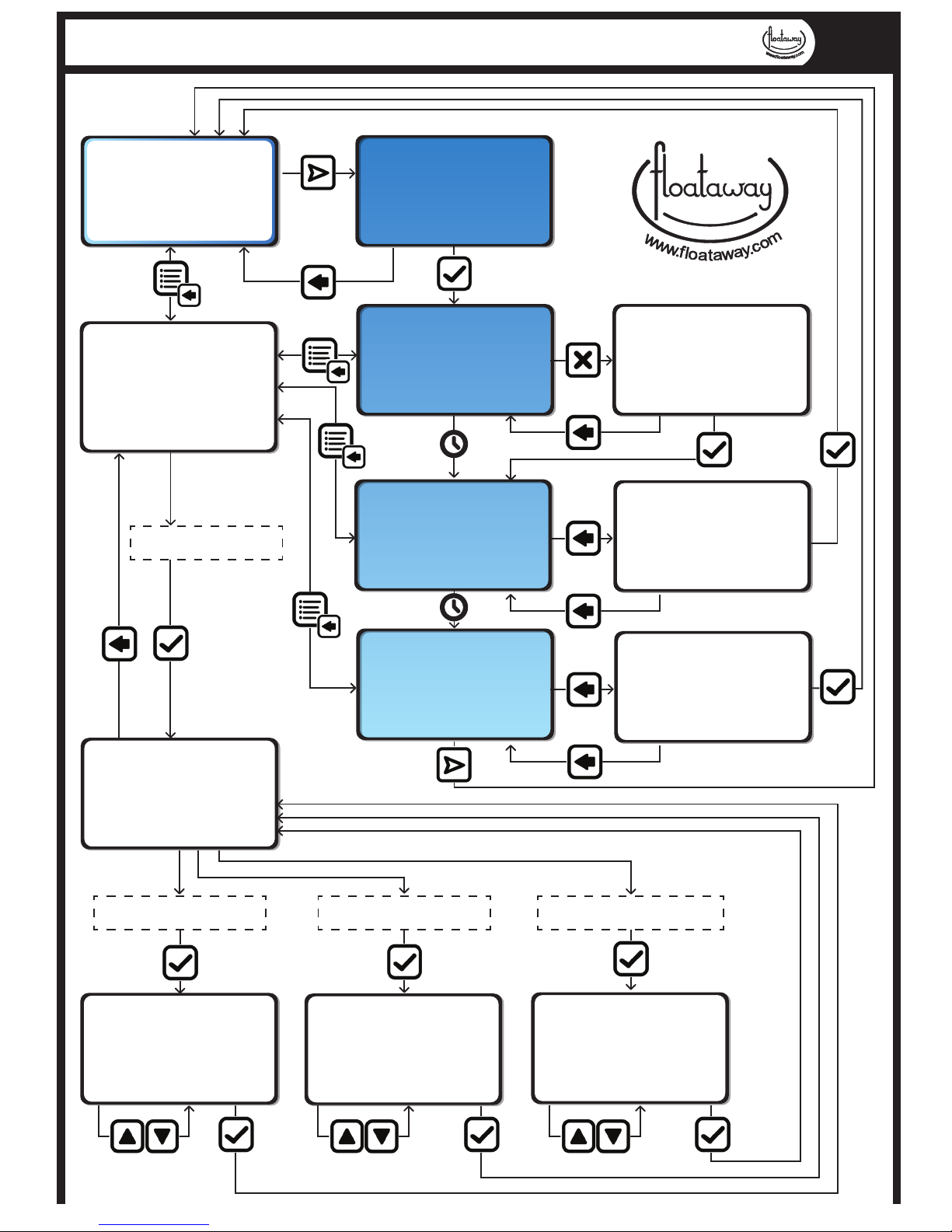
FLOATAWAY - FLOAT SESSION CONTROL
2015
B27RJ
End Session now?
Press OK to select
Or <-- to cancel
Ready to Float
Pumping in -- min
Temperature --.- C
Redox/ph Value ---
Select Menu or Start
Start a new session?
Press OK to Select
Or <-- to cancel
Now Floating
Time left -- mins
Temperature --.- C
Redox /ph Value ---
Select Menu or Start
End Session now?
Press OK to select
Or <-- to cancel
Session Ending
The Door is Open
The Lights are On
The Pump is On
BACK to end now
End Session now?
Press OK to select
Or <-- to cancel
Refreshing the tank
Pumping for -- mins
Temperature --.- C
Redox Value ---
Select Menu or Start
Menu Select Screen
Session Settings <-Pump Settings
Global Settings
Status Screen
Reset options
Session Settings <--
Session Settings
Adjust :
Music Settings <-Session Time -Temperature --.-
Music Settings <--
Adjust : Music
Music fade/on/o
Up/Down. Then OK
Session Settings <--
Adjust : St
Session Time
Change to : --
Up/Down. Then OK
Temperature Settings <--
Adjust : Temperature
Temperature --.-C
Change to : --.Up/Down. Then OK
Page 35
35
Floataway Installation Manual 230v 50Hz Tranquility 2017 - v3
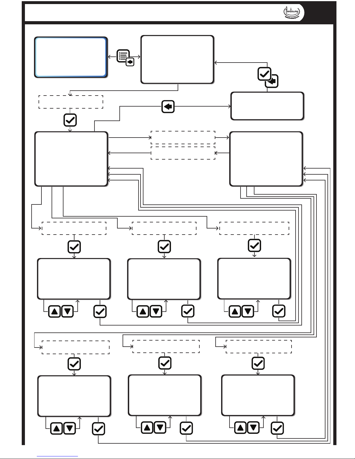
FLOATAWAY - PUMP SETTINGS
2015
B27RJ
Ready to Float
Pumping in -- min
Temperature --.- C
Redox/ph Value ---
Select Menu or Start
Menu Select Screen
Session Settings
Pump Settings <-Global Settings
Status Screen
Reset options
Pump Settings
Adjust:
Pump on time <-Pump dwell time
Start pump now
Stop pump now
Save changes
Press OK to Save
Or <-- to cancel
Adjust :
Pump on time t1
Change to : --
Up/Down. Then OK
Pump on time <--
Pump Settings <--
Adjust :
Pump dwell time t2
Change to : --
Up/Down. Then OK
Pump dwell time <--
Start Pump Now
Save changes
Start Pump Now <--
Stop Pump Now
Save changes
Stop Pump Now <--
Save Changes <--
Page 36
36
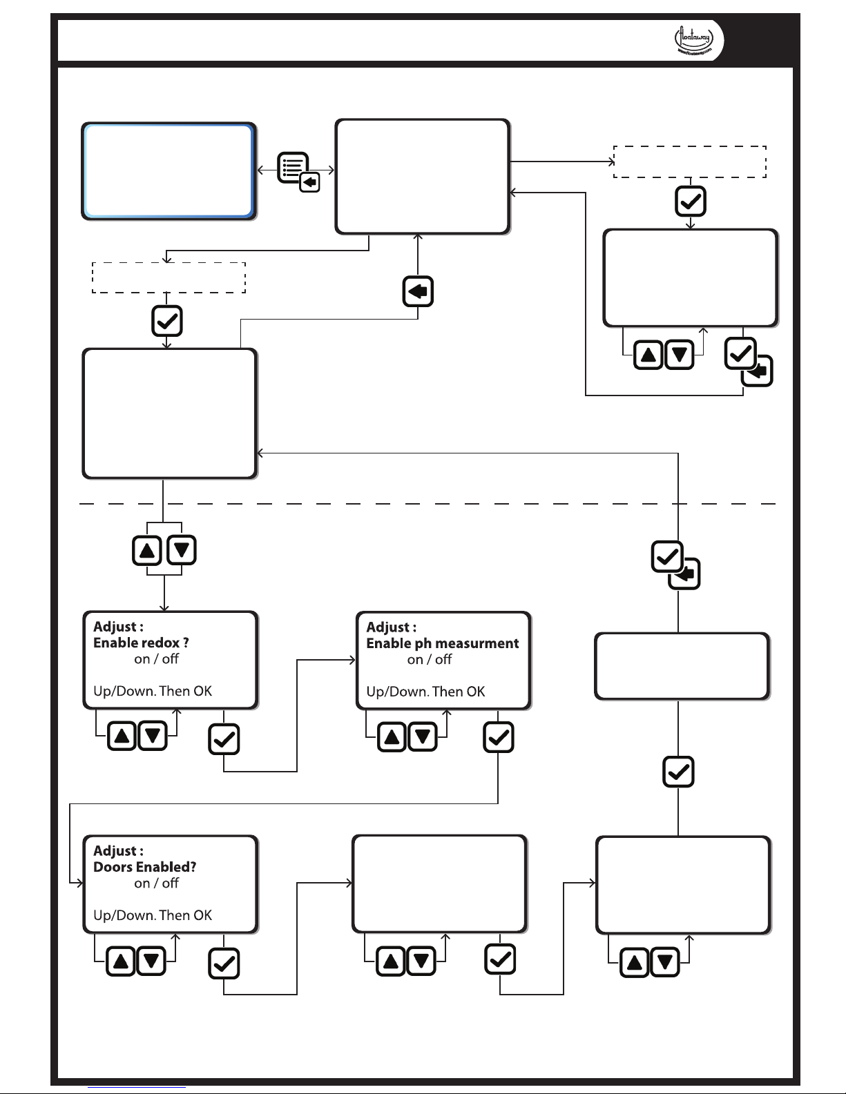
Floataway Installation Manual 230v 50Hz Tranquility 2017 - v3
FLOATAWAY - GLOBAL SETTINGS
2015
B27RJ
Ready to Float
Pumping in -- min
Temperature --.- C
Redox/ph Value ---
Select Menu or Start
Menu Select Screen
Session Settings
Pump Settings
Global Settings <-Status Screen
Reset options
Global Settings
Adjust:
Music Settings <-Session Time -Temperature --.-
More Options
Press OK to Save
Or <-- to cancel
Global Settings <--
More Options <--
Normal Settings
Adjust:
Autodose on time t3 <Autodose refresh t4
Music Fadeout time
Back
Back <--
Adjust :
Autodose on time t3
Change to : --
Up/Down. Then OK
Autodose on time t3 <--
Adjust :
Autodose refresh t4
Change to : --
Up/Down. Then OK
Autodose refresh t4 <--
Adjust :
Music Fadeout time fT
Change to : --
Up/Down. Then OK
Music fadeout time <--
Music Settings <--
Adjust : Music
Music fade/on/o
Up/Down. Then OK
Session Settings <--
Adjust :
Session Time : St
Change to : --
Up/Down. Then OK
Temperature Settings <--
Adjust : Temperature
Temperature --.-C
Change to : --.Up/Down. Then OK
Page 37
37
Floataway Installation Manual 230v 50Hz Tranquility 2017 - v3
FLOATAWAY - STATUS SCREEN / ENGINEER MENU
2015
B27RJ
Ready to Float
Pumping in -- min
Temperature --.- C
Redox/ph Value ---
Select Menu or Start
Menu Select Screen
Session Settings
Pump Settings
Global Settings
Status Screen <-Reset options
Status Screen
Session Count -Filter Count -Program version B27RJ
Status Screen <--
Reset Options
Reset to Normal ? <Reset to Factory ?
Reset Options <--
ENGINEER SETTINGS
Calibrate:Temperature
Temperature : --.Change to : --.-
--- -Up/Down. Then OK
Press OK to Save
Or <-- to cancel
Pump Refresh Time T5 RT
Time : --.Change to : --.-
Up/Down. Then OK
Page 38
38
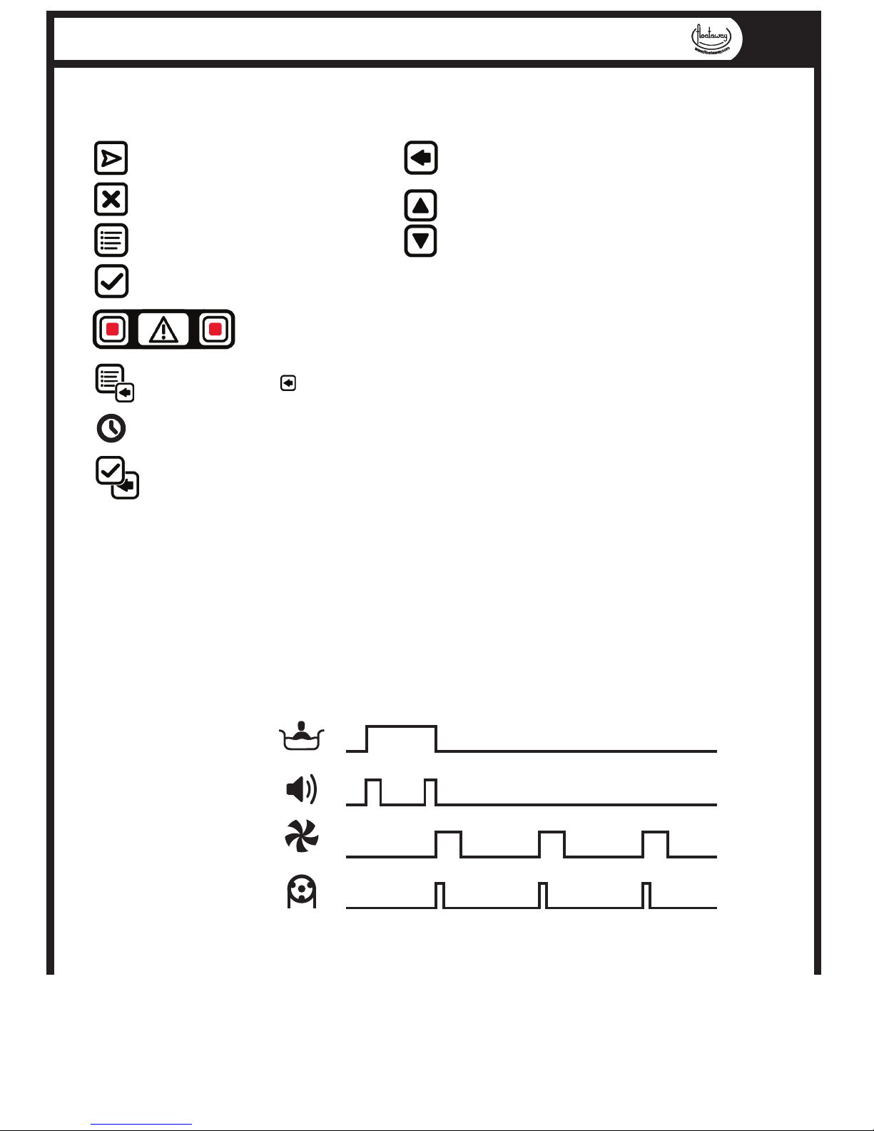
Floataway Installation Manual 230v 50Hz Tranquility 2017 - v3
FLOATAWAY - FLOAT CONTROL SYMBOLS & TIMES
2015
B27RJ
Start a new Float Seaaion
Stop the running Float Session
Menu
OK (yes)
Back (cancel) - if in settings, save
y/n is asked on using this button
Up / Down to navigate
the menu items
buzzer, the cancel button in the middle.
The Alarms are signaled by ashing red lights and an audable
Icon used when the is used to return to the last screen
Time between program states
This Icon is used for yes/no before returning to the last screen / level up in the menu
Floataway control symbols explained
Program times explained
The Floataway control system allows you to adjust the times os many aspects of the program to optimise your product to best work with your centre. The controller is based
around oat sessions and standby mode. The diagram below shows the corelation of the
dierent times in the program. The global settings are used as default, if the Session
settings menu is used before or during a oat session, it will eect that oat session only
and the program will return to the global settings automatically at the end of the oat
session.
t4 t3 t3
Rt
t2
t1 t1
t2
Ft
Float Session
St
Music Fade
Water Pump
Disinfectant
Autodose pump
 Loading...