


User’s manual
FLIR Exx series
T559597Publ. No.
a554Revision
English (EN)Language
September 27, 2011Issue date


User’s manual
Publ. No. T559597 Rev. a554 – ENGLISH (EN) – September 27, 2011

Legal disclaimer
All products manufactured by FLIR Systemsarewarranted against defectivematerialsandworkmanship for aperiodof one(1)year from the
delivery date of the original purchase, provided such products have been under normal storage, use and service, and in accordance with
FLIR Systems instruction.
Products which are not manufactured by FLIR Systems but included in systems delivered by FLIR Systems to the original purchaser, carry
the warranty, if any, of the particular supplier only. FLIR Systems has no responsibility whatsoever for such products.
The warranty extends only to the original purchaser and is not transferable. It is not applicable to any product which has been subjected to
misuse, neglect, accident or abnormal conditions of operation. Expendable parts are excluded from the warranty.
In the case of adefect inaproduct coveredbythis warrantytheproduct must notbe furtherusedin order toprevent additional damage.The
purchaser shall promptly report any defect to FLIR Systems or this warranty will not apply.
FLIR Systems will, at its option, repair or replace any such defective product free of charge if, upon inspection, it proves to be defective in
material or workmanship and provided that it is returned to FLIR Systems within the said one-year period.
FLIR Systems has no other obligation or liability for defects than those set forth above.
No other warranty is expressed or implied. FLIR Systems specifically disclaims the implied warranties of merchantability and fitness for a
particular purpose.
FLIR Systems shall not be liable for any direct, indirect, special, incidentalor consequential loss or damage, whether basedon contract, tort
or any other legal theory.
This warranty shall be governed by Swedish law.
Any dispute, controversy or claim arising out of or in connection with this warranty, shall be finally settled by arbitration in accordance with
the Rules of the Arbitration Institute of the Stockholm Chamber of Commerce. The place of arbitration shall be Stockholm. The language to
be used in the arbitral proceedings shall be English.
U.S. Government Regulations
The products described in the user documentation may require government authorization for export/re-export, or transfer. Contact FLIR
■
Systems for details.
Depending on license andexportprocedures,lensesmay be permanently fixed tocamerasshippedtocustomersoutside United States.
■
Interchangeable lenses fall under U.S. Department of State jurisdiction.
Copyright
© 2011, FLIRSystems. All rights reservedworldwide. No parts ofthesoftware including source codemaybe reproduced, transmitted, transcribed
or translated into any language or computer language in any form or by any means, electronic, magnetic, optical, manual or otherwise,
without the prior written permission of FLIR Systems.
This documentation must not, in whole or part, be copied, photocopied, reproduced, translated or transmitted to any electronic medium or
machine readable form without prior consent, in writing, from FLIR Systems.
Names and marks appearing on the products herein are eitherregistered trademarksor trademarksof FLIR Systems and/or its subsidiaries.
All othertrademarks,trade names or companynames referenced herein areusedfor identification only andarethe property of theirrespective
owners.
Quality assurance
The Quality Management System under which these products are developed and manufactured has been certified in accordance with the
ISO 9001 standard.
FLIR Systems is committed to a policy of continuous development; therefore we reserve the right to make changes and improvements on
any of the products described in this manual without prior notice.
Patents
One or several of the following patents or design patents apply to the products and/or features described in this manual:
0002258-2; 000279476-0001; 000439161; 000499579-0001; 000653423; 000726344; 000859020; 000889290; 001106306-0001; 001707738;
001707746; 001707787; 001776519; 0101577-5; 0102150-0; 0200629-4; 0300911-5; 0302837-0; 1144833; 1182246; 1182620; 1188086;
1285345; 1287138; 1299699; 1325808; 1336775; 1365299; 1402918; 1404291; 1678485; 1732314; 200530018812.0; 200830143636.7;
2106017; 235308; 3006596; 3006597; 466540; 483782; 484155; 518836; 60004227.8; 60122153.2; 602004011681.5-08; 6707044; 68657;
7034300; 7110035; 7154093; 7157705; 7237946; 7312822; 7332716; 7336823; 7544944; 75530; 7667198; 7809258; 7826736; D540838;
D549758; D579475; D584755; D599,392; DI6702302-9; DI6703574-4; DI6803572-1; DI6803853-4; DI6903617-9; DM/057692; DM/061609;
ZL00809178.1; ZL01823221.3; ZL01823226.4; ZL02331553.9; ZL02331554.7; ZL200480034894.0; ZL200530120994.2; ZL200630130114.4;
ZL200730151141.4; ZL200730339504.7; ZL200830128581.2.
EULA Terms
You have acquired a device (“INFRARED CAMERA”) that includes software licensed by FLIR Systems AB from Microsoft Licensing, GP
■
or its affiliates (“MS”). Those installed software products of MS origin, as well as associated media, printed materials, and “online” or
electronic documentation(“SOFTWARE”)are protected by internationalintellectualproperty laws and treaties.TheSOFTWARE is licensed,
not sold. All rights reserved.
iv Publ. No. T559597 Rev. a554 – ENGLISH (EN) – September 27, 2011

IF YOU DO NOTAGREE TO THISENDUSER LICENSE AGREEMENT(“EULA”), DONOT USE THEDEVICEOR COPY THE SOFTWARE.
■
INSTEAD, PROMPTLY CONTACT FLIR Systems AB FOR INSTRUCTIONS ON RETURN OF THE UNUSED DEVICE(S) FOR A REFUND.
ANY USE OF THE SOFTWARE, INCLUDING BUT NOT LIMITED TO USE ON THE DEVICE, WILL CONSTITUTE YOUR AGREEMENT
TO THIS EULA (OR RATIFICATION OF ANY PREVIOUS CONSENT).
GRANT OF SOFTWARE LICENSE. This EULA grants you the following license:
■
You may use the SOFTWARE only on the DEVICE.
■
NOT FAULT TOLERANT. THE SOFTWARE IS NOT FAULT TOLERANT. FLIR Systems AB HAS INDEPENDENTLY DETERMINED
■
HOW TOUSE THE SOFTWAREIN THE DEVICE,AND MS HASRELIED UPON FLIRSystems AB TOCONDUCT SUFFICIENT TESTING
TO DETERMINE THAT THE SOFTWARE IS SUITABLE FOR SUCH USE.
NO WARRANTIES FOR THE SOFTWARE. THE SOFTWARE is provided “AS IS” and with all faults. THE ENTIRE RISK AS TO SAT-
■
ISFACTORY QUALITY, PERFORMANCE, ACCURACY, AND EFFORT (INCLUDING LACK OF NEGLIGENCE) IS WITH YOU. ALSO,
THERE ISNO WARRANTY AGAINSTINTERFERENCE WITH YOURENJOYMENT OF THESOFTWAREOR AGAINST INFRINGEMENT.
IF YOU HAVE RECEIVED ANY WARRANTIES REGARDING THE DEVICE OR THE SOFTWARE, THOSE WARRANTIES DO NOT
ORIGINATE FROM, AND ARE NOT BINDING ON, MS.
No Liability for Certain Damages. EXCEPT AS PROHIBITED BY LAW, MS SHALL HAVE NO LIABILITY FOR ANY INDIRECT,
■
SPECIAL, CONSEQUENTIAL OR INCIDENTAL DAMAGES ARISING FROM OR IN CONNECTION WITH THE USE OR PERFORMANCE OF THE SOFTWARE. THIS LIMITATION SHALL APPLY EVEN IF ANY REMEDY FAILS OF ITS ESSENTIAL PURPOSE.
IN NO EVENT SHALL MS BE LIABLE FOR ANY AMOUNT IN EXCESS OF U.S. TWO HUNDRED FIFTY DOLLARS (U.S.$250.00).
Limitations on Reverse Engineering, Decompilation, and Disassembly. Youmay not reverse engineer, decompile,or disassemble
■
the SOFTWARE, exceptand only to the extentthat such activity isexpresslypermitted by applicable lawnotwithstandingthis limitation.
SOFTWARE TRANSFER ALLOWED BUT WITH RESTRICTIONS. Youmaypermanentlytransferrights under this EULA only aspart
■
of a permanent sale or transfer of the Device, and only if the recipient agrees to this EULA. If the SOFTWARE is an upgrade, any
transfer must also include all prior versions of the SOFTWARE.
EXPORT RESTRICTIONS. You acknowledge that SOFTWARE is subject to U.S. export jurisdiction. You agree to comply with all
■
applicable international andnationallawsthatapplytothe SOFTWARE, includingthe U.S. Export Administration Regulations,aswell
as end-user, end-use and destination restrictions issued by U.S. and other governments. For additional information see
http://www.microsoft.com/exporting/.
Publ. No. T559597 Rev. a554 – ENGLISH (EN) – September 27, 2011

vi Publ. No. T559597 Rev. a554 – ENGLISH (EN) – September 27, 2011

Table of contents
11 Warnings & Cautions .....................................................................................................................
42 Notice to user ..................................................................................................................................
53 Customer help ................................................................................................................................
64 Documentation updates .................................................................................................................
75 Important note about this manual .................................................................................................
86 Parts lists .........................................................................................................................................
86.1 Scope of delivery ..................................................................................................................
96.2 List of accessories and services ...........................................................................................
107 Quick Start Guide ...........................................................................................................................
118 Camera parts ...................................................................................................................................
118.1 View from the right ................................................................................................................
128.2 View from the left ..................................................................................................................
138.3 Keypad ..................................................................................................................................
158.4 View from the bottom ...........................................................................................................
168.5 Battery condition LED indicator ............................................................................................
178.6 Power LED indicator .............................................................................................................
188.7 Laser pointer .........................................................................................................................
209 Screen elements .............................................................................................................................
2110 Navigating the menu system .........................................................................................................
2211 Connecting external devices and storage media .......................................................................
2412 Pairing Bluetooth devices ..............................................................................................................
2513 Configuring Wi-Fi ............................................................................................................................
2714 Handling the camera ......................................................................................................................
2714.1 Turning on the camera .........................................................................................................
2714.2 Turning off the camera ..........................................................................................................
2814.3 Adjusting the infrared camera focus manually ....................................................................
2914.4 Operating the laser pointer ...................................................................................................
3015 Working with images ......................................................................................................................
3015.1 Previewing an image ............................................................................................................
3115.2 Saving an image ...................................................................................................................
3215.3 Opening an image ................................................................................................................
3315.4 Adjusting an image ...............................................................................................................
3615.5 Changing the palette ............................................................................................................
3715.6 Deleting an image .................................................................................................................
3815.7 Deleting all images ...............................................................................................................
3915.8 Creating a PDF report in the camera ...................................................................................
4016 Working with thermal fusion and picture-in-picture image modes ...........................................
Publ. No. T559597 Rev. a554 – ENGLISH (EN) – September 27, 2011 vii

4417 Working with measurement tools .................................................................................................
4417.1 Laying out measurement tools: spots, areas, etc. ...............................................................
4517.2 Laying out measurement tool: isotherms ............................................................................
4617.3 Moving or resizing a measurement tool ...............................................................................
4717.4 Creating and setting up a difference calculation .................................................................
4817.5 Changing object parameters ................................................................................................
5018 Fetching data from external Extech meters .................................................................................
5218.1 Typical moisture measurement and documentation procedure ..........................................
5319 Working with isotherms .................................................................................................................
5319.1 Building isotherms ................................................................................................................
5420 Annotating images ..........................................................................................................................
5520.1 Taking a digital photo ...........................................................................................................
5620.2 Creating a voice annotation .................................................................................................
5720.3 Creating a text annotation ....................................................................................................
5921 Recording video clips ....................................................................................................................
6022 Changing settings ..........................................................................................................................
6123 Cleaning the camera ......................................................................................................................
6123.1 Camera housing, cables, and other items ...........................................................................
6223.2 Infrared lens ..........................................................................................................................
6323.3 Infrared detector ...................................................................................................................
6424 Technical data .................................................................................................................................
6525 Dimensional drawings ...................................................................................................................
6525.1 Camera dimensions, front view (1) ......................................................................................
6625.2 Camera dimensions, front view (2) ......................................................................................
6725.3 Camera dimensions, side view (1) .......................................................................................
6825.4 Camera dimensions, side view (2) .......................................................................................
6925.5 Camera dimensions, side view (3) .......................................................................................
7025.6 Infrared lens (30 mm/15°) .....................................................................................................
7125.7 Infrared lens (10 mm/45°) .....................................................................................................
7225.8 Battery (1) .............................................................................................................................
7325.9 Battery (2) .............................................................................................................................
7425.10 Battery (3) .............................................................................................................................
7525.11 Battery charger (1) ................................................................................................................
7625.12 Battery charger (2) ................................................................................................................
7725.13 Battery charger (3) ................................................................................................................
7825.14 Battery charger (4) ................................................................................................................
7926 Application examples .....................................................................................................................
7926.1 Moisture & water damage ....................................................................................................
8026.2 Faulty contact in socket ........................................................................................................
8126.3 Oxidized socket ....................................................................................................................
8226.4 Insulation deficiencies ..........................................................................................................
8326.5 Draft ......................................................................................................................................
8427 Introduction to building thermography ........................................................................................
8427.1 Disclaimer .............................................................................................................................
viii Publ. No. T559597 Rev. a554 – ENGLISH (EN) – September 27, 2011

27.3.1.2 Guidelines for moisture detection, mold detection & detection of
water damages ..................................................................................
27.4.8 Excerpt from Technical Note ‘Assessing thermal bridging and insulation
continuity’ (UK example) ......................................................................................
8427.1.1 Copyright notice ...................................................................................................
8427.1.2 Training & certification ..........................................................................................
8427.1.3 National or regional building codes .....................................................................
8427.2 Important note ......................................................................................................................
8527.3 Typical field investigations ....................................................................................................
8527.3.1 Guidelines .............................................................................................................
8527.3.1.1 General guidelines ............................................................................
85
8627.3.1.3 Guidelines for detection of air infiltration & insulation deficiencies ...
8727.3.2 About moisture detection .....................................................................................
8727.3.3 Moisture detection (1): Low-slope commercial roofs ..........................................
8727.3.3.1 General information ...........................................................................
8827.3.3.2 Safety precautions ............................................................................
8927.3.3.3 Commented building structures .......................................................
9027.3.3.4 Commented infrared images ............................................................
9227.3.4 Moisture detection (2): Commercial & residential façades ..................................
9227.3.4.1 General information ...........................................................................
9227.3.4.2 Commented building structures .......................................................
9427.3.4.3 Commented infrared images ............................................................
9427.3.5 Moisture detection (3): Decks & balconies ..........................................................
9427.3.5.1 General information ...........................................................................
9527.3.5.2 Commented building structures .......................................................
9727.3.5.3 Commented infrared images ............................................................
9727.3.6 Moisture detection (4): Plumbing breaks & leaks ................................................
9727.3.6.1 General information ...........................................................................
9827.3.6.2 Commented infrared images ............................................................
10027.3.7 Air infiltration .........................................................................................................
10027.3.7.1 General information ...........................................................................
10027.3.7.2 Commented building structures .......................................................
10227.3.7.3 Commented infrared images ............................................................
10327.3.8 Insulation deficiencies ..........................................................................................
10327.3.8.1 General information ...........................................................................
10327.3.8.2 Commented building structures .......................................................
10527.3.8.3 Commented infrared images ............................................................
10727.4 Theory of building science ...................................................................................................
10727.4.1 General information ..............................................................................................
10827.4.2 The effects of testing and checking .....................................................................
10927.4.3 Sources of disruption in thermography ................................................................
11127.4.4 Surface temperature and air leaks .......................................................................
11127.4.4.1 Pressure conditions in a building .....................................................
11727.4.5 Measuring conditions & measuring season .........................................................
11727.4.6 Interpretation of infrared images ..........................................................................
11927.4.7 Humidity & dew point ...........................................................................................
11927.4.7.1 Relative & absolute humidity ............................................................
11927.4.7.2 Definition of dew point ......................................................................
119
11927.4.8.1 Credits ...............................................................................................
12027.4.8.2 Introduction .......................................................................................
12027.4.8.3 Background information ...................................................................
12127.4.8.4 Quantitative appraisal of thermal anomalies ....................................
12427.4.8.5 Conditions and equipment ...............................................................
Publ. No. T559597 Rev. a554 – ENGLISH (EN) – September 27, 2011 ix

12527.4.8.6 Survey and analysis ..........................................................................
12627.4.8.7 Reporting ...........................................................................................
12828 Introduction to thermographic inspections of electrical installations ......................................
12828.1 Important note ......................................................................................................................
12828.2 General information ..............................................................................................................
12828.2.1 Introduction ...........................................................................................................
12928.2.2 General equipment data .......................................................................................
13028.2.3 Inspection .............................................................................................................
13028.2.4 Classification & reporting ......................................................................................
13128.2.5 Priority ...................................................................................................................
13128.2.6 Repair ....................................................................................................................
13228.2.7 Control ..................................................................................................................
13328.3 Measurement technique for thermographic inspection of electrical installations ...............
13328.3.1 How to correctly set the equipment .....................................................................
13328.3.2 Temperature measurement ...................................................................................
13528.3.3 Comparative measurement ..................................................................................
13628.3.4 Normal operating temperature .............................................................................
13728.3.5 Classification of faults ...........................................................................................
13928.4 Reporting ..............................................................................................................................
14128.5 Different types of hot spots in electrical installations ...........................................................
14128.5.1 Reflections ............................................................................................................
14128.5.2 Solar heating .........................................................................................................
14228.5.3 Inductive heating ...................................................................................................
14228.5.4 Load variations ......................................................................................................
14328.5.5 Varying cooling conditions ...................................................................................
14428.5.6 Resistance variations ............................................................................................
14428.5.7 Overheating in one part as a result of a fault in another ......................................
14628.6 Disturbance factors at thermographic inspection of electrical installations ........................
14628.6.1 Wind ......................................................................................................................
14628.6.2 Rain and snow ......................................................................................................
14728.6.3 Distance to object .................................................................................................
14828.6.4 Object size ............................................................................................................
15028.7 Practical advice for the thermographer ................................................................................
15028.7.1 From cold to hot ...................................................................................................
15028.7.2 Rain showers ........................................................................................................
15028.7.3 Emissivity ..............................................................................................................
15128.7.4 Reflected apparent temperature ...........................................................................
15128.7.5 Object too far away ...............................................................................................
15229 About FLIR Systems .......................................................................................................................
15329.1 More than just an infrared camera .......................................................................................
15429.2 Sharing our knowledge ........................................................................................................
15429.3 Supporting our customers ...................................................................................................
15429.4 A few images from our facilities ...........................................................................................
15630 Glossary ...........................................................................................................................................
16031 Thermographic measurement techniques ...................................................................................
16031.1 Introduction ..........................................................................................................................
16031.2 Emissivity ..............................................................................................................................
16131.2.1 Finding the emissivity of a sample .......................................................................
16131.2.1.1 Step 1: Determining reflected apparent temperature .......................
16331.2.1.2 Step 2: Determining the emissivity ...................................................
x Publ. No. T559597 Rev. a554 – ENGLISH (EN) – September 27, 2011

16431.3 Reflected apparent temperature ..........................................................................................
16431.4 Distance ................................................................................................................................
16431.5 Relative humidity ..................................................................................................................
16431.6 Other parameters ..................................................................................................................
16532 History of infrared technology ......................................................................................................
16933 Theory of thermography ................................................................................................................
16933.1 Introduction ...........................................................................................................................
16933.2 The electromagnetic spectrum ............................................................................................
17033.3 Blackbody radiation ..............................................................................................................
17133.3.1 Planck’s law ..........................................................................................................
17233.3.2 Wien’s displacement law ......................................................................................
17433.3.3 Stefan-Boltzmann's law .........................................................................................
17533.3.4 Non-blackbody emitters .......................................................................................
17733.4 Infrared semi-transparent materials .....................................................................................
17934 The measurement formula .............................................................................................................
18535 Emissivity tables .............................................................................................................................
18535.1 References ............................................................................................................................
18535.2 Important note about the emissivity tables ..........................................................................
18635.3 Tables ....................................................................................................................................
Publ. No. T559597 Rev. a554 – ENGLISH (EN) – September 27, 2011 xi

xii Publ. No. T559597 Rev. a554 – ENGLISH (EN) – September 27, 2011

1 Warnings & Cautions
(Applies only to Class A digital devices.) This equipment generates, uses, and
WARNING
■
can radiate radio frequency energy and if not installed and used in accordance
with the instruction manual, may cause interference to radio communications. It
has beentested andfound to complywith the limitsfor a ClassA computing device
pursuant to Subpart J of Part 15 of FCC Rules, which are designed to provide
reasonable protection against such interference when operated in a commercial
environment. Operation of this equipment in a residential area is likely to cause
interference in which case the user at his own expense will be required to take
whatever measures may be required to correct the interference.
(Applies only to Class B digital devices.) This equipment has been tested and
■
found to comply with the limits for a Class B digital device, pursuant to Part 15 of
the FCC Rules. Theselimits are designedto provide reasonableprotection against
harmful interference in a residential installation. This equipment generates, uses
and canradiate radiofrequencyenergy and, ifnot installed andused in accordance
with the instructions, may cause harmful interference to radio communications.
However, there is no guarantee that interference will not occur in a particular installation. If this equipment does cause harmful interference to radio or television
reception, whichcan be determinedby turning the equipmentoff and on,the user
is encouraged to try to correct the interference by one or more of the following
measures:
Reorient or relocate the receiving antenna.
■
Increase the separation between the equipment and receiver.
■
Connect the equipment into an outlet on a circuit different from that to which
■
the receiver is connected.
Consult the dealer or an experienced radio/TV technician for help.
■
(Applies only to digital devices subject to 15.19/RSS-210.) NOTICE: This device
■
complies with Part 15 of the FCC Rules and with RSS-210 of Industry Canada.
Operation is subject to the following two conditions:
1 this device may not cause harmful interference, and
2 this device must accept any interference received, including interference that
may cause undesired operation.
(Applies only to digital devices subject to 15.21.) NOTICE: Changes or modifica-
■
tions made to this equipment not expressly approved by (manufacturer name)
may void the FCC authorization to operate this equipment.
(Applies onlyto digitaldevicessubject to2.1091/2.1093/OETBulletin 65.) Radiofre-
■
quency radiation exposure Information: Theradiated output powerof the device
is far below the FCC radio frequency exposure limits. Nevertheless, the device
shall beused in such amanner that the potentialfor human contact duringnormal
operation is minimized.
(Applies only to cameras with laser pointer:) Do not look directly into the laser
■
beam. The laser beam can cause eye irritation.
Applies only to cameras with battery:
■
Do not disassemble or do a modification to the battery. The battery contains
■
safety and protection devices which, if they become damaged, can cause the
battery to become hot, or cause an explosion or an ignition.
Publ. No. T559597 Rev. a554 – ENGLISH (EN) – September 27, 2011 1

1 – Warnings & Cautions
■
CAUTION
■
■
■
■
If there is a leak from the battery and the fluid gets into your eyes, do not rub
■
your eyes.Flush well withwater and immediatelyget medical care. Thebattery
fluid can cause injury to your eyes if you do not do this.
Do not continue to charge the battery if it does not become charged in the
■
specified charging time. If you continue to charge the battery, it can become
hot and cause an explosion or ignition.
Only use the correct equipment to discharge the battery. If you do not use the
■
correct equipment, you can decrease the performance or the life cycle of the
battery. If you do not use the correct equipment, an incorrect flow of current
to the battery can occur. This can cause the battery to become hot, or cause
an explosion and injury to persons.
Make sure that you read all applicable MSDS (Material Safety Data Sheets) and
warning labelson containersbeforeyou usea liquid: theliquids can bedangerous.
Do not point theinfrared camera (withor without the lens cover)at intensive energy
sources, for example devices that emit laser radiation, or the sun. This can have
an unwanted effect on the accuracy of the camera. It can also cause damage to
the detector in the camera.
Do not use the camera in a temperature higher than +50°C (+122°F), unless
specified otherwise in the user documentation. High temperatures can cause
damage to the camera.
(Applies only to cameras with laser pointer:) Protect the laser pointer with the
protective cap when you do not operate the laser pointer.
Applies only to cameras with battery:
Do not attach the batteries directly to a car’s cigarette lighter socket, unless a
■
specific adapter for connecting the batteries to a cigarette lighter socket is
provided by FLIR Systems.
Do not connect the positive terminal and the negative terminal of the battery
■
to each other with a metal object (such as wire).
Do not get water or salt water on the battery, or permit the battery to get wet.
■
Do not make holes in the battery with objects. Do not hit the battery with a
■
hammer. Do not step on the battery, or apply strong impacts or shocks to it.
Do not put thebatteries inor near a fire, orinto direct sunlight. When thebattery
■
becomes hot, the built-in safety equipment becomes energized and can stop
the battery charging process. If the battery becomes hot, damage can occur
to the safety equipment and this can cause more heat, damage or ignition of
the battery.
Do not put the battery on a fire or increase the temperature of the battery with
■
heat.
Do not put the battery on or near fires, stoves, or other high-temperature loca-
■
tions.
Do not solder directly onto the battery.
■
Do not use the battery if, when you use, charge, or store the battery, there is
■
an unusual smell fromthe battery,the battery feelshot, changes color, changes
shape, or is in an unusual condition. Contact your sales office if one or more
of these problems occurs.
Only use a specified battery charger when you charge the battery.
■
2 Publ. No. T559597 Rev. a554 – ENGLISH (EN) – September 27, 2011

1 – Warnings & Cautions
The temperature range through which you can charge the battery is ±0°C to
■
+45°C (+32°F to +113°F), unless specified otherwise in the user documentation. If you charge the battery at temperatures out of this range, it can cause
the battery to become hot or to break. It can also decrease the performance
or the life cycle of the battery.
The temperature range through which you can dischargethe battery is −15°C
■
to +50°C (+5°F to +122°F), unless specified otherwise in the user documentation. Use of the battery out of this temperature range can decrease the performance or the life cycle of the battery.
When the battery is worn, apply insulation to the terminals with adhesive tape
■
or similar materials before you discard it.
Remove any water or moisture on the battery before you install it.
■
Do not apply solvents or similar liquids to the camera, the cables, or other items.
■
This can cause damage.
Be careful when you cleanthe infraredlens. The lens has a delicate anti-reflective
■
coating.
Do not clean the infrared lens too vigorously. This can damage the anti-reflective
■
coating.
In furnace and other high-temperature applications,you mustmount aheatshield
■
on the camera. Using the camera in furnace and other high-temperature applications without a heatshield can cause damage to the camera.
(Applies only to cameras with an automatic shutter that can be disabled.) Do not
■
disable the automatic shutter in the camera for a prolonged time period (typically
max. 30 minutes). Disabling the shutter for a longer time period may harm, or irreparably damage, the detector.
The encapsulationratingis valid onlywhen all openings onthe camera are sealed
■
with their designated covers, hatches, or caps. This includes, but is not limited
to, compartments for data storage, batteries, and connectors.
Publ. No. T559597 Rev. a554 – ENGLISH (EN) – September 27, 2011 3

2 Notice to user
Typographical
conventions
User-to-user
forums
Calibration
Accuracy
Disposal of
electronic waste
This manual uses the following typographical conventions:
Semibold is used for menu names, menu commands and labels, and buttons in
■
dialog boxes.
Italic is used for important information.
■
Monospace is used for code samples.
■
UPPER CASE is used for names on keys and buttons.
■
Exchange ideas,problems, and infraredsolutions with fellowthermographers around
the world in our user-to-user forums. To go to the forums, visit:
http://www.infraredtraining.com/community/boards/
(This notice only applies to cameras with measurement capabilities.)
We recommend that you send in the camera for calibration once a year. Contact
your local sales office for instructions on where to send the camera.
(This notice only applies to cameras with measurement capabilities.)
For very accurate results, we recommend that you wait 5 minutes after you have
started the camera before measuring a temperature.
For cameras where the detector is cooled by a mechanical cooler, this time period
excludes the time it takes to cool down the detector.
10742803;a1
As with most electronic products, this equipment must be disposed of in an environmentally friendlyway, and in accordancewith existingregulationsfor electronicwaste.
Please contact your FLIR Systems representative for more details.
Training
To read about infrared training, visit:
http://www.infraredtraining.com
■
http://www.irtraining.com
■
http://www.irtraining.eu
■
4 Publ. No. T559597 Rev. a554 – ENGLISH (EN) – September 27, 2011

3 Customer help
General
Submitting a
question
Downloads
For customer help, visit:
http://support.flir.com
To submit a question to the customer help team, you must be a registered user. It
only takes a fewminutes to registeronline. If you only wantto search the knowledgebase for existing questions and answers, you do not need to be a registered user.
When you want to submit a question, makesure thatyou have the following information to hand:
The camera model
■
The camera serial number
■
The communication protocol, or method, between the camera and your PC (for
■
example, HDMI, Ethernet, USB™, or FireWire™)
Operating system on your PC
■
Microsoft®Office version
■
Full name, publication number, and revision number of the manual
■
On the customer help site you can also download the following:
Firmware updates for your infrared camera
■
Program updates for your PC software
■
User documentation
■
Application stories
■
Technical publications
■
Publ. No. T559597 Rev. a554 – ENGLISH (EN) – September 27, 2011 5

4 Documentation updates
General
Our manuals are updated several times per year, and we also issue product-critical
notifications of changes on a regular basis.
To access the latest manuals and notifications, go to the Download tab at:
http://support.flir.com
It only takes a few minutes to register online. In the download area you will also find
the latest releases of manuals for our other products, as well as manuals for our
historical and obsolete products.
6 Publ. No. T559597 Rev. a554 – ENGLISH (EN) – September 27, 2011

5 Important note about this manual
General
NOTE
FLIR Systems issues generic manuals that cover several cameras within a model
line.
This means that this manual may contain descriptions and explanations that do not
apply to your particular camera model.
FLIR Systemsreserves the rightto discontinuemodels,software, parts oraccessories,
and other items, or to change specifications and/or functionality at any time without
prior notice.
Publ. No. T559597 Rev. a554 – ENGLISH (EN) – September 27, 2011 7

6 Parts lists
6.1 Scope of delivery
Infrared camera with lens
Contents
■
Hard transport case
■
Battery (2*)
■
Bluetooth headset*
■
Calibration certificate
■
FLIR Tools PC software CD-ROM
■
Handstrap
■
Lens cap
■
Memory card
■
Power supply, including multi-plugs
■
Printed Getting Started Guide
■
Printed Important Information Guide
■
USB cable
■
User documentation CD-ROM
■
Video cable
■
Warranty extension card or Registration card
■
* Dependent on the camera model/customer configuration.
NOTE
FLIR Systems reserves the right to discontinue models, parts or accessories, and
other items, or to change specifications at any time without prior notice.
8 Publ. No. T559597 Rev. a554 – ENGLISH (EN) – September 27, 2011

6.2 List of accessories and services
6 – Parts lists
General
Accessories and
services
This section contains a list of accessories and services that you can purchase for
your camera.
1196497 Cigarette lighter adapter kit, 12 VDC, 1.2 m/3.9 ft.
■
1196960 IR lens f = 10 mm, 45° including case
■
1196961 IR lens f = 30 mm, 15° including case
■
1910423 USB cable Std A to Mini-B
■
1910582 Video cable
■
ITC-ADV-3011 ITC Advanced Building—attendance 1 person
■
ITC-ADV-3019 ITC Advanced Building—group of 10 persons
■
ITC-ADV-3021 ITC Advanced General Thermography Course—attendance, 1
■
person
ITC-ADV-3029ITCAdvanced General Thermography Course—groupof10 persons
■
ITC-CER-5101 ITC Level 1 Thermography Course—attendance, 1 person
■
ITC-CER-5109 ITC Level 1 Thermography Course—group of 10 persons
■
ITC-CER-5201 ITC Level 2 Thermography Course—attendance, 1 person
■
ITC-CER-5209 ITC Level 2 Thermography Course—group of 10 persons
■
T197453 FLIR ResearchIR 1.2
■
T197453L10 FLIR ResearchIR 1.2, 10 user licenses
■
T197453L5 FLIR ResearchIR 1.2, 5 user licenses
■
T197454 FLIR QuickPlot 1.2
■
T197454L10 FLIR QuickPlot 1.2, 10 user licenses
■
T197454L5 FLIR QuickPlot 1.2, 5 user licenses
■
T197717 FLIR Reporter 8.5 SP2, Professional
■
T197717L10 FLIR Reporter 8.5 SP2, Professional, 10 user licenses
■
T197717L5 FLIR Reporter 8.5 SP2, Professional, 5 user licenses
■
T197771 Bluetooth headset
■
T197778 FLIR BuildIR 2.1
■
T197778L10 FLIR BuildIR 2.1, 10 user licenses
■
T197778L5 FLIR BuildIR 2.1, 5 user licenses
■
T910737 Memory card micro-SD with adapters
■
T910972 EX845: Clamp meter + IR therm TRMS 1000A AC/DC
■
T910973 MO297: Moisture meter, pinless with memory
■
NOTE
FLIR Systems reserves the right to discontinue models, parts or accessories, and
other items, or to change specifications at any time without prior notice.
Publ. No. T559597 Rev. a554 – ENGLISH (EN) – September 27, 2011 9

7 Quick Start Guide
Procedure
NOTE
Follow this procedure to get started right away:
Put a battery into the battery compartment.1
Charge the battery for 4 hours before starting the camera for the first time,
2
or until the green battery condition LED glows continuously.
Insert a memory card into a card slot.3
4
Push the button to turn on the camera.
Aim the camera towards the object of interest.5
Focus the camera by rotating the focus ring.6
Pull and hold the trigger for more than 1 second to save an image directly.7
Move the image to a computer by doing one of the following:
8
Remove the memory card and insert it in a card reader connected to a
■
computer.
Connect a computer to the camera using a USB mini-B cable.
■
Move theimage from the cardorcamera, using adrag-and-dropoperation.9
You can also move the images to the computer using FLIR Tools, which comes with
your camera.
10 Publ. No. T559597 Rev. a554 – ENGLISH (EN) – September 27, 2011

8 Camera parts
8.1 View from the right
Figure
Explanation
T638786;a1
This table explains the figure above:
Cover for the right-hand connectors compartment:
1
USB-A.
■
USB mini-B.
■
Power.
■
Trigger to preview/save images.2
Tripod mount. Requires an adapter (extra accessory).3
Focus ring.4
Infrared lens.5
Publ. No. T559597 Rev. a554 – ENGLISH (EN) – September 27, 2011 11

8 – Camera parts
8.2 View from the left
Figure
Explanation
T638790;a1
This table explains the figure above:
Laser pointer.1
Lamp for the digital camera.2
Digital camera.3
Cover for connectors and storage media:
4
Memory card.
■
Video out.
■
12 Publ. No. T559597 Rev. a554 – ENGLISH (EN) – September 27, 2011

8.3 Keypad
8 – Camera parts
Figure
T638787;a2
Explanation
This table explains the figure above:
Touch-screen LCD.1
Navigation pad.2
Button to confirm choice.
3
■
Button to switch between automatic and manual adjustment modes.
■
Image archive.4
Button to operate the laser pointer.5
Power indicator.6
On/off button.7
Publ. No. T559597 Rev. a554 – ENGLISH (EN) – September 27, 2011 13

8 – Camera parts
Button to display the menu system.
8
■
Back button.
■
14 Publ. No. T559597 Rev. a554 – ENGLISH (EN) – September 27, 2011
8.4 View from the bottom
8 – Camera parts
Figure
Explanation
T638785;a3
This table explains the figure above:
Latch to open the cover for the battery compartment. Push to open.1
Publ. No. T559597 Rev. a554 – ENGLISH (EN) – September 27, 2011 15

8 – Camera parts
8.5 Battery condition LED indicator
Figure
Explanation
T638791;a1
This table explains the battery condition LED indicator:
ExplanationType of signal
The battery is being charged.The green LED flashes two times per
second.
The battery is fully charged.The green LED glows continuously.
16 Publ. No. T559597 Rev. a554 – ENGLISH (EN) – September 27, 2011
8.6 Power LED indicator
8 – Camera parts
Figure
T638781;a1
Explanation
This table explains the power LED indicator:
ExplanationType of signal
The camera is off.The LED is off.
The camera is on.The LED is blue.
Publ. No. T559597 Rev. a554 – ENGLISH (EN) – September 27, 2011 17

8 – Camera parts
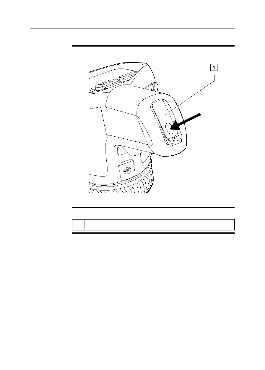
8.7 Laser pointer
General
Figure
The camera has a laser pointer. When the laser pointer is on, you can see a laser
dot above the target.
This figure showsthe difference in position between the laser pointer and the optical
center of the infrared lens:
T638771;a1
WARNING
Do not look directly into the laser beam. The laser beam can cause eye irritation.
NOTE
The symbol is displayed on the screen when the laser pointer is on.
■
The laser pointer may not be enabled in all markets.
■
Laser warning
label
A laser warning label with the following information is attached to the camera:
10743603;a2
18 Publ. No. T559597 Rev. a554 – ENGLISH (EN) – September 27, 2011

8 – Camera parts
Laser rules and
regulations
Wavelength: 635 nm. Maximum output power: 1 mW.
This product complies with 21 CFR 1040.10 and 1040.11 except for deviations pur-
suant to Laser Notice No. 50, dated June 24, 2007.
Publ. No. T559597 Rev. a554 – ENGLISH (EN) – September 27, 2011 19

9 Screen elements
Figure
Explanation
T638713;a3
This table explains the figure above:
Measurement result table.1
Measurement tools (e.g., spotmeter).2
Status and mode icons.3
Temperature scale.4
Setup mode.5
Video mode recording.6
Camera mode/live image mode.7
View mode (infrared camera, digital camera, thermal fusion, picture-in-pic-
8
ture).
Measurement tools.9
Color palettes.10
Measurement parameters.11
Zoom.12
20 Publ. No. T559597 Rev. a554 – ENGLISH (EN) – September 27, 2011

10 Navigating the menu system
Figure
Explanation
T638777;a1 T638780;a1
The figure above shows the two ways to navigate the menu system in the camera:
Using the index finger to navigate the menu system (left).
■
Using the navigation pad to navigate the menu system (right).
■
Publ. No. T559597 Rev. a554 – ENGLISH (EN) – September 27, 2011 21

11 Connecting external devices and
storage media
Figure
T638789;a4
Explanation
22 Publ. No. T559597 Rev. a554 – ENGLISH (EN) – September 27, 2011
This table explains the figure above:
Indicator showing that the memory card is busy. Note: Do not remove the
1
memory card when this indicator is glowing.
Memory card.2
Headset cable.3

11 – Connecting external devices and storage media
Figure
T638788;a1
Explanation
This table explains the figure above:
Power cable.1
USB mini-B cable (to connect the camera to a PC).2
USB-A cable (to connect the camera to an external device, e.g., a USB
3
memory stick).
Publ. No. T559597 Rev. a554 – ENGLISH (EN) – September 27, 2011 23

12 Pairing Bluetooth devices
General
Procedure
NOTE
Before youcan use a Bluetoothdevicewith the camera,youneed to pairthedevices.
Follow this procedure:
1
Go to (Settings).
Go to the Connectivity tab.2
Activate Bluetooth.
3
Note: You also need to activate Bluetooth connectivity on the external de-
vice.
Select Add Bluetooth device.4
Select Scan for Bluetooth device, and wait until a list of available devices
5
is displayed. This will take about 15 seconds.
When a Bluetooth device is found, select the device to add it. The device
6
is now ready to be used.
You can add several devices.
■
You can remove an added device by selecting the device and and then selecting
■
Remove.
After adding a MeterLink device, such as the Extech MO297 or EX845, the result
■
from the meter will be visible in the measurement result table.
After adding a Bluetooth-enabledheadset,it isready to beused in camerapreview
■
mode.
It is also possible to add live snapshot values in preview mode.
■
24 Publ. No. T559597 Rev. a554 – ENGLISH (EN) – September 27, 2011
13 Configuring Wi-Fi
General
Setting up a
peer-to-peer
connection (most
common use)
Depending on yourcamera configuration, you can connect the camera to a wireless
local area network (WLAN) using Wi-Fi, or let the camera provide Wi-Fi access to
another device.
You can connect the camera in two different ways:
Most common use: Setting up a peer-to-peer connection (also called ad hoc or
■
P2P connection). This methodis primarily usedwith other devices,e.g., aniPhone
or iPad.
Less common use: Connecting the camera to a WLAN.
■
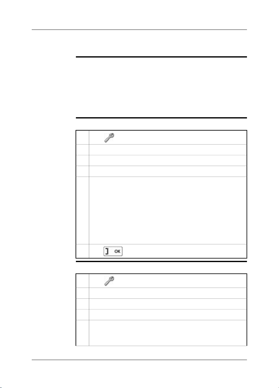
Follow this procedure:
1
Go to (Settings) .
Go to the Connectivity tab.2
Under Wi-Fi, select Connect device.3
Select Wi-Fi settings.4
Enter values for the following parameters:
5
SSID (the name of the network).
■
Channel (the channel that the other device is broadcasting on).
■
Encryption (the encryption algorithm, e.g., TKIP or AES).
■
Key (the access key to the network).
■
Address (the IP address for the network).
■
Gateway (the gateway IP address for the network).
■
Note: These parameters are set for your camera's network. They will be
used by the external device to connect that device to the network.
6
Push to confirm the choice.
Connecting the
Follow this procedure:
camera to a
wireless local area
network (less
common use)
1
Go to (Settings) .
Go to the Connectivity tab.2
Under Wi-Fi, select Connect to WLAN.3
Select Wi-Fi settings.4
Select one of the available networks.
5
Password-protected networks are indicated with a padlock icon, and for
these you will need to enter an access key.
Publ. No. T559597 Rev. a554 – ENGLISH (EN) – September 27, 2011 25

13 – Configuring Wi-Fi
6
Push to confirm the choice.
NOTE
Some networksdo notbroadcasttheir existence.To connect tosuch a network,select
Add manually and set all parameters manually according to that network.
26 Publ. No. T559597 Rev. a554 – ENGLISH (EN) – September 27, 2011

14 Handling the camera
14.1 Turning on the camera
Procedure
To turn on the camera, push and release the button.
14.2 Turning off the camera
Procedure
To turn off the camera, push and hold the button for more than 0.2 second.
Publ. No. T559597 Rev. a554 – ENGLISH (EN) – September 27, 2011 27

14 – Handling the camera
14.3 Adjusting the infrared camera focus manually
Do not touch thelens surface whenyou adjust theinfrared camera focusmanually.
NOTE
■
If this happens, clean the lens according to the instructions in section 23.2 – Infrared lens on page 62.
The focus ring can be rotated infinitely, but only a certain amount of rotation is
■
needed when focusing.
Figure
T638779;a1
Procedure
Do one of the following:
For far focus, rotatethe focusring counter-clockwise (lookingat the touch-screen
■
LCD side).
For near focus, rotate the focus ring clockwise (looking at the touch-screen LCD
■
side).
28 Publ. No. T559597 Rev. a554 – ENGLISH (EN) – September 27, 2011

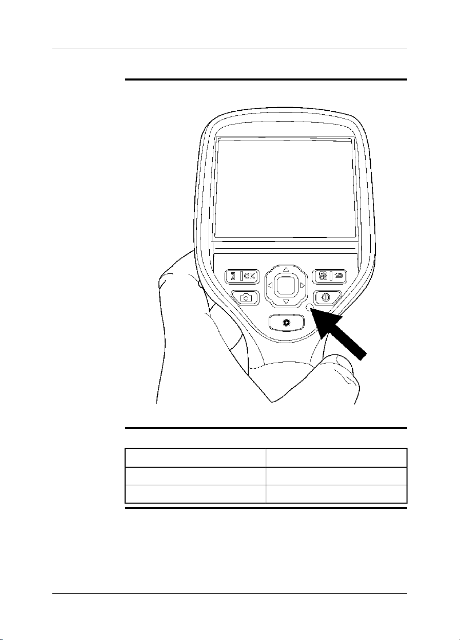
14.4 Operating the laser pointer
14 – Handling the camera
Figure
Procedure
T638778;a1
Follow this procedure to operate the laser pointer:
To turn on the laser pointer, push and hold the laser button.1
To turn off the laser pointer, release the laser button.2
A warning indicator is displayed on the screen when the laser pointer is turned
NOTE
■
on.
The position of the laser dot is indicated on the infraredimage (depending on the
■
camera model).
Publ. No. T559597 Rev. a554 – ENGLISH (EN) – September 27, 2011 29

15 Working with images
15.1 Previewing an image
General
Procedure
NOTE
You can preview an infrared image or a digital photo before you save it to a memory
card. Thisenables you toseeif the imageor photo containsthe information you want
before you save it.
In preview mode, you can also manipulate the image before you save it, and add
annotations.
To preview an image, briefly pull and release the trigger.
You can change the function of the trigger under (Settings). The function can
be set to one of the following:
Preview/Save.
■
Save directly.
■
Always preview.
■
30 Publ. No. T559597 Rev. a554 – ENGLISH (EN) – September 27, 2011

15.2 Saving an image
15 – Working with images
General
Image capacity
Naming
convention
Procedure
NOTE
You can save an image directly, without previewing the image first.
This table gives information on the approximate number of infrared (IR) and digital
camera (DC) images that can be saved on memory cards:
IR + DCIR onlyCard size
IR + DC + 30
seconds voice
annotation
60085055001 GB
1200170011 0002 GB
The naming convention for images is IR_xxxx.jpg, where xxxx is a unique counter.
To save an image directly, pull and hold down the trigger for more than 1 second.
You can change the function of the trigger in the Settings menus. The function can
be set to one of the following:
Preview/Save.
■
Save directly.
■
Always preview.
■
Publ. No. T559597 Rev. a554 – ENGLISH (EN) – September 27, 2011 31

15 – Working with images
15.3 Opening an image
General
Procedure
When yousave an image,the image isstored on amemory card. Todisplay the image
again, open it from the memory card.
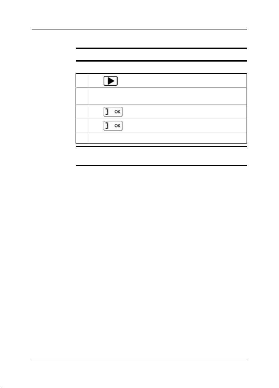
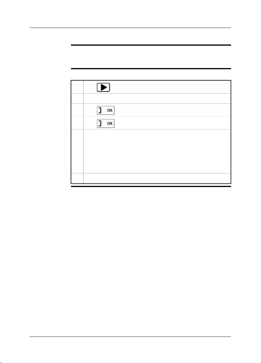
Follow this procedure to open an image:
1
Push .
Push the navigation pad up/down or left/right to select the image you want
2
to view.
3
Push . This will display the image at full size.
4
To edit the opened image, push the button, which will bring up a
menu.
32 Publ. No. T559597 Rev. a554 – ENGLISH (EN) – September 27, 2011

15.4 Adjusting an image
15 – Working with images
General
Example 1
An image can be adjusted automatically or manually. You use the button
to switch between these two modes. Note that this only works in live mode and not
in preview/archive mode.
This figure shows two infrared images of cable connection points. In the left image
a correct analysis of the left cable is difficult to do if you only auto-adjust the image.
You can analyze the left cable in more detail if you
change the temperature scale level
■
change the temperature scale span.
■
The image on the left has been auto-adjusted. In the right image the maximum and
minimum temperaturelevels have beenchangedto temperaturelevelsnear the object.
On the temperature scale to the rightof each imageyou can seehow thetemperature
levels were changed.
10577503;a2
Publ. No. T559597 Rev. a554 – ENGLISH (EN) – September 27, 2011 33

15 – Working with images
Example 2
This figure shows two infrared images of an isolator in a power line.
In the image onthe left the cold skyand the power line structurehave been recorded
at a minimumtemperature of –26.0°C (–14.8°F).In theright image the maximum and
minimum temperature levels have been changed to temperature levels near the isolator. This makes it easier to analyze the temperature variations in the isolator.
10742503;a3
34 Publ. No. T559597 Rev. a554 – ENGLISH (EN) – September 27, 2011

15 – Working with images
Changing the
temperature scale
level
Changing the
temperature scale
span
NOTE
Follow this procedure to change the temperature scale level:
1
Push .
2
Use the navigation pad to select (Manual).
To change the scale level, push the navigation pad up/down.3
Follow this procedure to change the temperature scale span:
1
Push .
2
Use the navigation pad to select (Manual).
To change the scale span, push the navigation pad left/right.3
These procedures only apply to live image mode.
Publ. No. T559597 Rev. a554 – ENGLISH (EN) – September 27, 2011 35

15 – Working with images
15.5 Changing the palette
General
Procedure
You can change the color palette that the camera uses to display different temperatures. A different palette can make it easier to analyze an image.
Follow this procedure to change the palette:
1
Push to display the menu system.
2
Use the navigation pad to go to .
3
Push to display a submenu.
Use the navigation pad to select a different palette.4
5
Push .
36 Publ. No. T559597 Rev. a554 – ENGLISH (EN) – September 27, 2011
15.6 Deleting an image
15 – Working with images
General
Procedure
NOTE
You can delete one or more images in a folder.
Follow this procedure to delete an image:
1
Push .
Push the navigation pad up/down or left/right to select the image you want
2
to delete.
3
Push to display the image.
4
Push to display a menu.
On the menu, select Delete and confirm the choice.5
Note that all images in the same group will be deleted at the same time, e.g., digital
photos.
Publ. No. T559597 Rev. a554 – ENGLISH (EN) – September 27, 2011 37

15 – Working with images
15.7 Deleting all images
General
Procedure
You can delete all images in a folder.
Follow this procedure to delete an image:
1
Push .
Push the navigation pad up/down or left/right to select any image.2
3
Push to display the image.
4
Push to display a menu.
On the menu, select Delete all and confirm the choice.5
38 Publ. No. T559597 Rev. a554 – ENGLISH (EN) – September 27, 2011
15.8 Creating a PDF report in the camera
15 – Working with images
General
Procedure
You can create a PDF report in the camera. You can then transfer the PDF report to
a computer, iPhone, or iPad using the FLIR Viewer app, and send the report to a
customer.
Follow this procedure to create a PDF report:
1
Push .
Push the navigation pad up/down or left/right to select an image.2
3
Push to display the image.
4
Push to display a menu.
On the menu, select Create report.
5
This will display a menu where you can change the following:
Header.
■
Footer.
■
Logo. (The location ofthe logo shouldbe /report/logo/and the fileformat
■
*.jpg.)
On the menu, select Create report.6
Publ. No. T559597 Rev. a554 – ENGLISH (EN) – September 27, 2011 39

16 Working with thermal fusion and
picture-in-picture image modes
What is thermal
fusion?
What is picture-inpicture?
Types
Image examples
Thermal fusion is a function that lets you display part of a digital photo as an infrared
image.
For example, you can set the camera to display all areas of an image that have a
certain temperature in infrared, with all other areas displayed as a digital photo.
Picture-in-picture is similar to thermal fusion in that it lets you display part of a digital
photo as an infrared image.
However, picture-in-picture displays an infrared imageframe on topof adigital photo.
Depending on the camera model, up to four different types are available. These are:
Above: All areas in the digital photo with a temperature above the specified tem-
■
perature level are displayed in infrared.
Below: All areas in the digital photo with a temperature below the specified tem-
■
perature level are displayed in infrared.
Interval: All areas in the digital photo with a temperature between two specified
■
temperature levels are displayed in infrared.
Picture-in-Picture: An infrared image frame is displayed on top of the digital
■
photo.
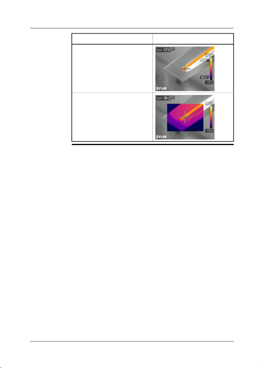
This table explains the four different types:
ImageFusion type
Above
Below
40 Publ. No. T559597 Rev. a554 – ENGLISH (EN) – September 27, 2011
16 – Working with thermal fusion and picture-in-picture image modes
Interval
Picture-in-Picture
ImageFusion type
Publ. No. T559597 Rev. a554 – ENGLISH (EN) – September 27, 2011 41
16 – Working with thermal fusion and picture-in-picture image modes
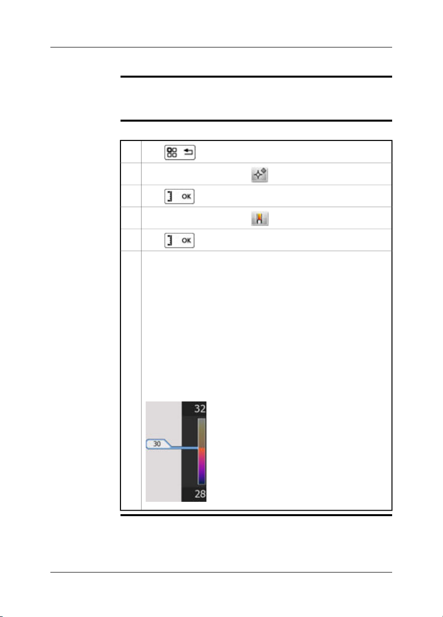
Procedure to set
up thermal fusion
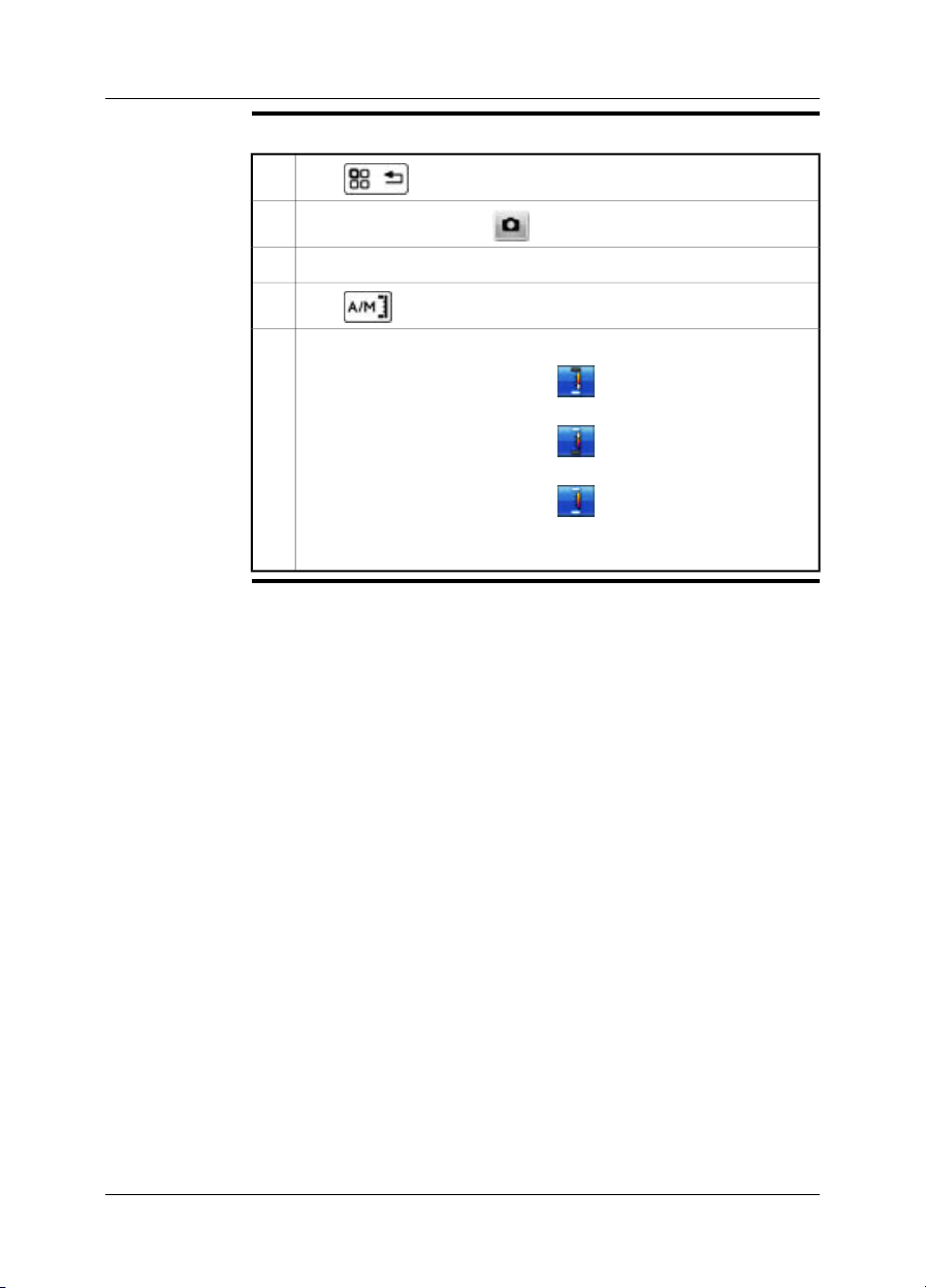
Follow this procedure:
1
Push to display the menu system.
2
In the menu system, select . This will display a submenu.
In the submenu, select Thermal fusion.3
4
Push .
To change the portion of infrared in the image, do one of the following:
5
Push the joystick left/rightto select , then pushthe joystick up/down
■
to change the bottom temperature level.
Push the joystick left/rightto select , then pushthe joystick up/down
■
to change the top temperature level.
Push the joystick left/rightto select , then pushthe joystick up/down
■
to change the top and bottom temperature level at the same time, and
left/right to change the temperature span.
42 Publ. No. T559597 Rev. a554 – ENGLISH (EN) – September 27, 2011

16 – Working with thermal fusion and picture-in-picture image modes
Procedure to set
up picture-in-picture
Follow this procedure:
1
Push to display the menu system.
2
In the menu system, select . This will display a submenu.
In the submenu, select Picture-in-Picture.
3
This will display an infrared image frame on top of a digital photo.
Publ. No. T559597 Rev. a554 – ENGLISH (EN) – September 27, 2011 43
17 Working with measurement tools
17.1 Laying out measurement tools: spots, areas, etc.
General
Procedure
To measurea temperature, youuse one ormore measurement tools,e.g., a spotmeter
or a box.
Follow this procedure to lay out a measurement tool:
1
Push to display the menu system.
2
Use the navigation pad to go to .
3
Push to display a submenu.
Use the navigation pad to go to a measurement tool.4
5
Push . This will display the measurement tool on the screen.
44 Publ. No. T559597 Rev. a554 – ENGLISH (EN) – September 27, 2011
17 – Working with measurement tools
17.2 Laying out measurement tool: isotherms
General
Procedure
The isotherm command applies a contrasting color to all pixels with a temperature
above, below, or between one or more set temperature levels.
Using isotherms is a good methodto easily discover anomalies in an infraredimage.
Follow this procedure to lay out an isotherm:
1
Push to display the menu system.
2
Use the navigation pad to go to .
3
Push to display a submenu.
4
Use the navigation pad to go to .
5
Push . This will display a submenu.
In the submenu, select one of the following:
6
Above. Thiswill apply a contrasting colorto all pixelswith a temperature
■
above one or more set temperature levels.
Below. This will applya contrastingcolor to all pixels witha temperature
■
below one or more set temperature levels.
Interval. This will applya contrasting color to allpixels with a temperature
■
between two or more set temperature levels.
Humidity. This will apply a contrasting color to all pixels with a tempera-
■
ture below a threshold calculated by humidity parameters.
Insulation. This will apply a contrasting color to all pixels with a temper-
■
ature below a threshold calculated by insulation parameters.
This will display a flag in thetemperature scale.To changethe temperature
level, tap and drag the flag up or down. See the image below.
T639069;a1
Publ. No. T559597 Rev. a554 – ENGLISH (EN) – September 27, 2011 45

17 – Working with measurement tools
17.3 Moving or resizing a measurement tool
General
NOTE
Procedure
You can move and resize a measurement tool.
This procedure assumes that you have previously laid out a measurement tool
■
on the screen.
You can also move and resize the measurement tool using your finger.
■
Follow this procedure to move or resize a measurement tool:
1
Push to display the menu system.
2
Use the navigation pad to go to (Tools).
3
Push to display a submenu.
4
Use the navigation pad to go to (Adjust tools).
5
Push and select the measurement tool that you want to move or
resize.
Use the navigation pad to move or resize the measurement tool.6
46 Publ. No. T559597 Rev. a554 – ENGLISH (EN) – September 27, 2011

17 – Working with measurement tools
17.4 Creating and setting up a difference calculation
General
NOTE
Procedure
A difference calculation gives the difference between the values of two known measurement results.
This procedure assumesthat you have previously laid out at least two measurement
tools on the screen.
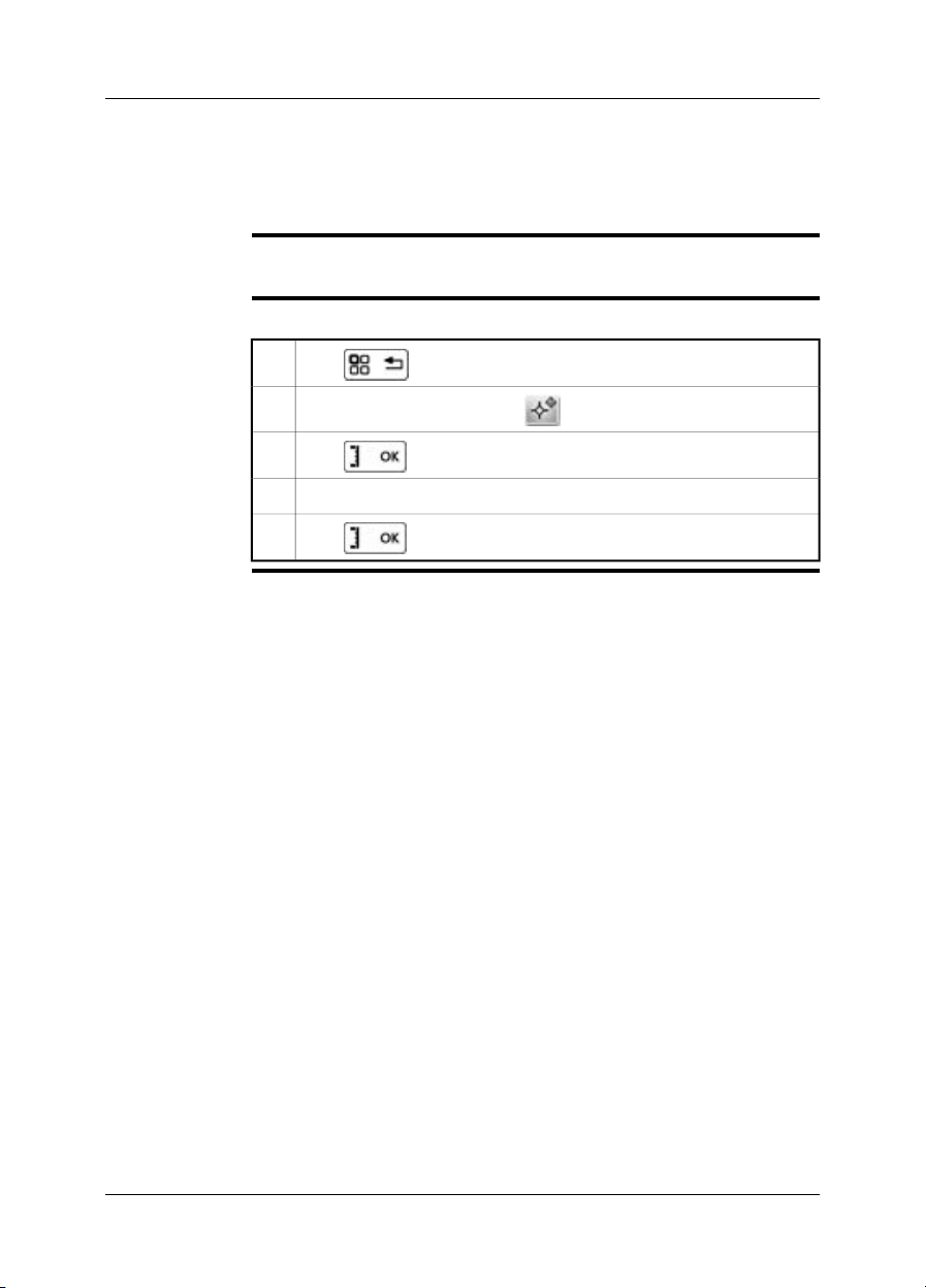
Follow this procedure to create and set up a difference calculation:
1
Push to display the menu system.
2
Use the navigation pad to go to (Tools).
3
Push to display a submenu.
4
Use the navigation pad to select (Add difference).
5
Push . This will display a dialog box where you can select the
measurement tools that you want to use in the difference calculation.
6
Push . The result of the difference calculation is now displayed in
the result table.
Publ. No. T559597 Rev. a554 – ENGLISH (EN) – September 27, 2011 47

17 – Working with measurement tools
17.5 Changing object parameters
General
Types of
parameters
Recommended
values
For accurate measurements, you must set the object parameters.
The camera can use these object parameters:
Emissivity, i.e., how much radiation an object emits, compared with the radiation
■
of a theoretical reference object of the same temperature (called a “blackbody”).
The opposite of emissivity is reflectivity. The emissivity determines how much of
the radiation originates from the object as opposed to being reflected by it.
Reflected apparent temperature, which is used when compensating for the radi-
■
ation from the surroundings reflected by the objectinto thecamera. This property
of the object is called reflectivity.
Object distance, i.e., the distance between the camera and the object of interest.
■
Atmospheric temperature, i.e., the temperature of the air between the camera
■
and the object of interest.
Relative humidity, i.e., the relative humidity of the air between the camera and
■
the object of interest.
External IR window compensation, i.e., the temperature ofany protective windows,
■
etc., that are setup betweenthe camera and the objectof interest.If no protective
window or protective shield is used, this value is irrelevant and should be left inactive.
If you are unsure about the values, the following are recommended:
Atmospheric temperature +20°C (+69°F)
0.95Emissivity
1.0 m (3.3 ft.)Object distance
+20°C (+69°F)Reflected apparent temperature
50%Relative humidity
48 Publ. No. T559597 Rev. a554 – ENGLISH (EN) – September 27, 2011

17 – Working with measurement tools
Procedure
NOTE
Related topics
Follow this procedure to change the object parameters:
1
Push to display the menu system.
2
Use the navigation pad to go to .
3
Push to display a dialog box.
Use the navigation pad to select and change an object parameter.4
5
Push . This will close the dialog box.
Of the parameters above, emissivity and reflected apparent temperature are the two
most important to set correctly in the camera.
For in-depth information about parameters, and how to correctly set the emissivity
and reflected apparent temperature, see section 31 – Thermographic measurement
techniques on page 160.
Publ. No. T559597 Rev. a554 – ENGLISH (EN) – September 27, 2011 49

18 Fetching data from external
Extech meters
General
Figure
Supported Extech
meters
You can fetch data from an external Extech meter and merge this data into the result
table in the infrared image.
T638370;a1
Extech Moisture Meter MO297
■
Extech Clamp Meter EX845
■
Technical support
for Extech meters
NOTE
Procedure
support@extech.com
This support is for Extech meters only. For technical support for infrared cameras,
go to http://support.flir.com.
This procedure assumes that you have paired the Bluetooth devices.
■
For more information about products from Extech Instruments, go to
■
http://www.extech.com/instruments/.
Follow this procedure:
Turn on the camera.1
Turn on the Extech meter.2
50 Publ. No. T559597 Rev. a554 – ENGLISH (EN) – September 27, 2011

18 – Fetching data from external Extech meters
On the meter, enable Bluetooth mode. Refer to the user documentation for
3
the meter for information on how to do this.
On the meter, choose the quantity that you want to use (voltage, current,
4
resistance, etc.). Refer to the user documentation forthe meter for information on how to do this.
Results from the meterwill now automaticallybe displayed inthe resulttable
in the top left corner of the infrared camera screen.
Do one of the following:
5
To preview an image, push the Preview/Save button. At this stage, you
■
can add additional values. To do so, take a new measurement with the
meter and select Add on the infrared camera screen.
To save an image without previewing, push and hold down the Pre-
■
view/Save button.
(Dependent on camera model) To add a value to a recalled image, turn
■
on the meter after you have recalled the image, then select Add on the
infrared camera screen. A maximum of eight values can be added, but
note that some values are broken into two lines.
Publ. No. T559597 Rev. a554 – ENGLISH (EN) – September 27, 2011 51

18 – Fetching data from external Extech meters
18.1 Typical moisture measurement and documentation procedure
General
Procedure
The followingprocedure can form the basisfor other proceduresusing Extech meters
and infrared cameras.
Follow this procedure:
Use the infrared camera to identify any potential damp areas behind walls
1
and ceilings.
Use the moisture meter to measure the moisture levels at various suspect
2
locations that may have been found.
When a spot of particular interest is located, store the moisture reading in
3
the moisture meter’s memory and identify the measurement spot with a
handprint or other thermal identifying marker.
Recall the reading from the meter memory. The moisture meter will now
4
continuously transmit this reading to the infrared camera.
Use the camera to take a thermal image of the area with the identifying
5
marker. The stored data from the moisture meter will also be saved on the
image.
52 Publ. No. T559597 Rev. a554 – ENGLISH (EN) – September 27, 2011
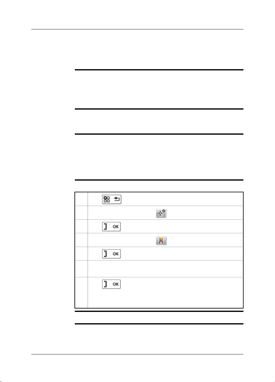
19 Working with isotherms
19.1 Building isotherms
General
About the
Humidity isotherm
About the
Insulation
isotherm
Procedure
The camera features isotherm types that are specific to the building trade. You can
make the camera trigger the following types of isotherms:
Humidity: Triggers when a measurement tool detects a surfacewhere therelative
■
humidity exceeds a preset value.
Insulation: Triggers when there is an insulation deficiency in a wall.
■
To detect areas where the relative humidity is less than 100% you can use the Humidity isotherm, where you can set the relative humidity above which the isotherm
will colorize the image.
The Insulation isotherm can detect areas wherethere may bean insulation deficiency
in the building. It will trigger when the insulation level falls below a preset value of
the energy leakage through a wall.
Different building codes recommend different values, but typical values for the insulation level are 0.6–0.8 for new buildings. Refer to your national building code for
recommendations.
Follow this procedure to set up an isotherm:
1
Push to display the menu system.
2
Use the navigation pad to go to .
3
Push to display a submenu.
4
Use the navigation pad to go to .
5
Push . This will display a submenu.
In the submenu, select Humidity or Insulation. This will display a dialog
6
box where you can set the necessary parameters.
7
Push .
The setup is now complete, and an isotherm will be displayed when the
parameters are met.
NOTE
Publ. No. T559597 Rev. a554 – ENGLISH (EN) – September 27, 2011 53
For this isotherm to be meaningful, the parameters must be set with some care.

20 Annotating images
General
This section describes how to save additional information in an infrared image by
using annotations.
Using annotations makes reporting and post-processing more efficient by providing
essential informationabout the image,e.g., conditions,photos,and informationabout
where an image is taken.
You can set the camera to automatically add an annotation to your images.
54 Publ. No. T559597 Rev. a554 – ENGLISH (EN) – September 27, 2011

20.1 Taking a digital photo
20 – Annotating images
General
NOTE
Procedure
When you save an infrared image you can also take a digital photo of the object of
interest. This digital photo will automatically be grouped together with the infrared
image, which will simplify post-processing and reporting.
This procedure assumes that you have not set the camera to automatically add a
digital photo.
Follow this procedure to take a digital photo:
To preview an infrared image, briefly pull and release the trigger.1
2
Use the navigation pad to select .
3
Push to display a submenu.
Use the navigation pad to select Digital camera photo.4
Push to take the digital photo.
The digital photo will now be added to to what is called an “group,” and
will be grouped together with the infrared image in the image archive, and
also when moving files from the camera to reporting software on the computer.
Publ. No. T559597 Rev. a554 – ENGLISH (EN) – September 27, 2011 55
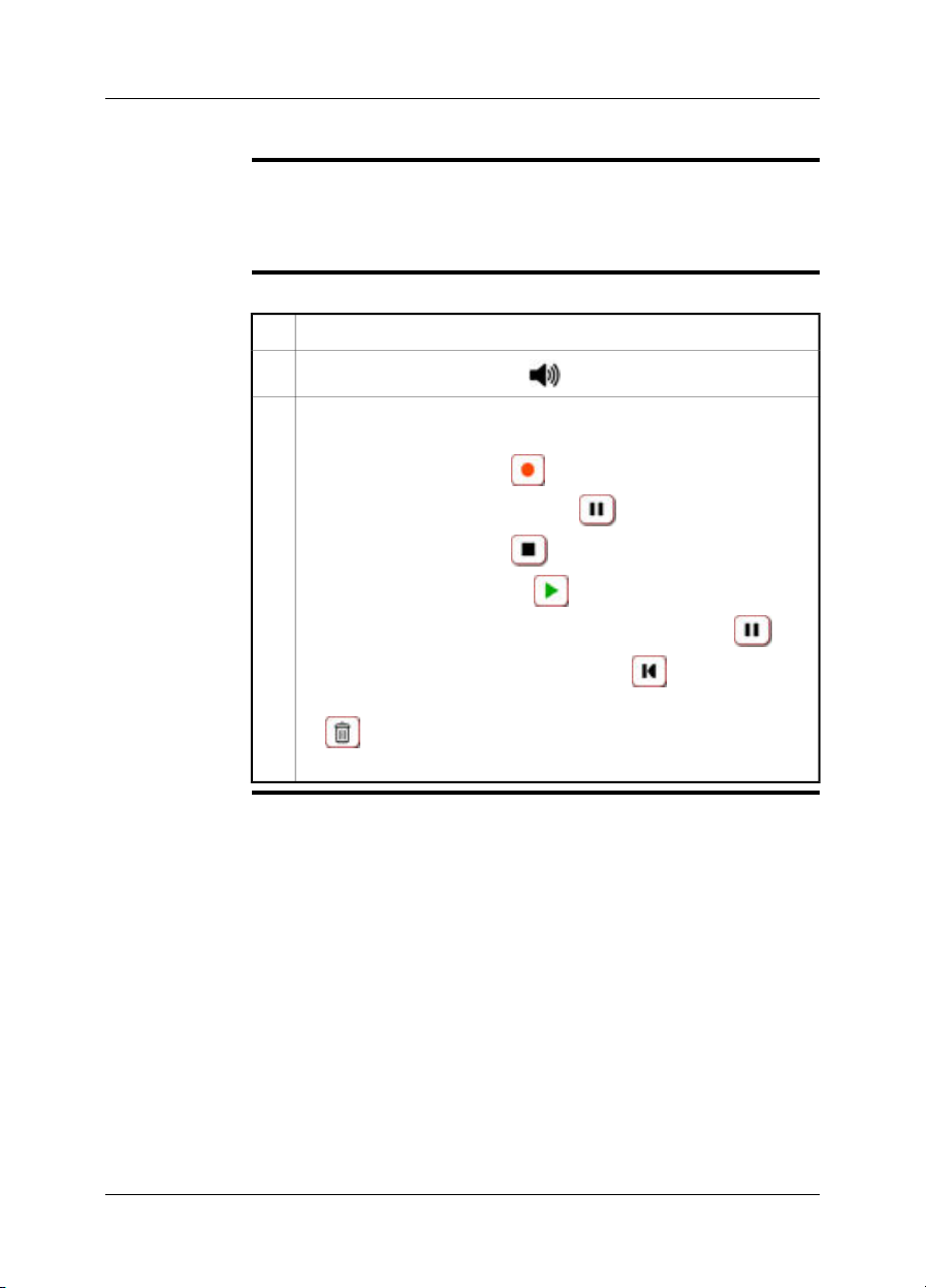
20 – Annotating images
20.2 Creating a voice annotation
General
Procedure
A voice annotation is an audio recording that is stored in an infrared image file.
The voice annotation is recorded using a Bluetooth headset. The recording can be
played back in the camera, and in image analysis and reporting software from FLIR
Systems.
Follow this procedure to create a voice annotation:
To preview an image, pull the trigger.1
2
Use the navigation pad to select .
Do one or more of the following, and push the joystick to confirm each
3
choice. Some buttons have more than one function.
To start a recording, select .
■
To pause/resume a recording, select .
■
To stop a recording, select .
■
To listen to a recording, select .
■
To pause a voice annotation that you are listening to, select .
■
To go to the beginning of a recording, select .
■
To delete arecording, movethe joystick left/right or up/down and select
■
.
To save a recording, select Save.
■
56 Publ. No. T559597 Rev. a554 – ENGLISH (EN) – September 27, 2011

20.3 Creating a text annotation
20 – Annotating images
General
NOTE
Procedure
A text annotation is grouped with an image file. Using this feature, you can annotate
images. This text can be revised later.
This feature is very efficient when saving information on an image when you are inspecting a large number of similar objects. Using text annotations avoids filling out
forms or inspection protocols manually.
This procedure assumes that you have not set the camera to automatically add a
text annotation.
Follow this procedure to create a text annotation:
To preview an image, pull the trigger.1
2
Use the navigation pad to select .
3
Push to display a dialog box.
T639064;a1
4
In this dialog box you can do one of the following:
Use an existing text annotation template, or create a new template.
■
Create new fields.
■
Enter new text values for the fields.
■
The text annotation will now be added to to what is called a group, and will
be grouped together with the infrared image in the image archive,and also
when moving files from the camera to reporting software on the computer.
(Step 5–8 describes how to add values to existing labels.)
5
Use the navigation pad to select a label in the list, e.g., Location or Object.
6
Push to display a dialog box.
Publ. No. T559597 Rev. a554 – ENGLISH (EN) – September 27, 2011 57

20 – Annotating images
In this dialog, do one of the following:
7
Select one of the predefined descrptions, e.g., engine or vent.
■
Click Keyboard and type in a new description.
■
Click OK.8
58 Publ. No. T559597 Rev. a554 – ENGLISH (EN) – September 27, 2011
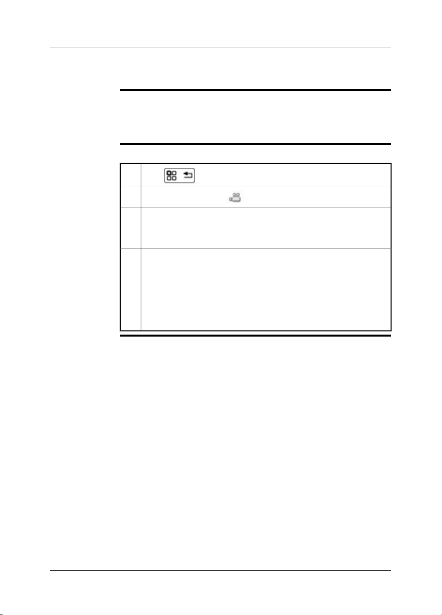
21 Recording video clips
General
Procedure
You can record non-radiometric infrared or visual video clips. In this mode, the
camera can be regarded as an ordinary digital video camera.
The video clips can be played back in Microsoft Windows Media Player, but it will
not be possible to retrieve radiometric information from the video clips.
Follow this procedure to record infrared or visual non-radiometric video clips:
1
Push to display the menu system.
2
Use the joystick to go to .
Do the following:
3
To start a recording, briefly push and release the Preview/Save button.
■
To stop a recording, briefly push and release the Preview/Save button.
■
When you have stopped the recording, a toolbar will be presented where
4
you can do one or more of the following:
Save the recording.
■
Cancel the recording.
■
Play back the recording.
■
Add a text annotation.
■
Add a sketch.
■
Publ. No. T559597 Rev. a554 – ENGLISH (EN) – September 27, 2011 59

22 Changing settings
General
Procedure
You can change a variety of settings for the camera:
Camera settings, e.g., the display intensity, power management, touch-screen
■
calibration, and default settings.
Preferences, e.g., settings for annotations and overlay.
■
Connectivity, e.g., settings for Wi-Fi and Bluetooth.
■
Regional settings, e.g., the language, date and time, date and time format, and
■
temperature and distance units.
This area also contains uneditable camera information, e.g., the serial number,
firmware version, and battery level.
Follow this procedure to change settings:
1
Push to display the menu system.
2
Use the navigation pad to go to (Settings) .
3
Push . This will display a dialog box.
Do the following:
4
Use the navigation pad to go between tabs and up/down on tabs.
■
Use the button to edit the currently selected setting.
■
Use the button to confirm choices.
■
60 Publ. No. T559597 Rev. a554 – ENGLISH (EN) – September 27, 2011

23 Cleaning the camera
23.1 Camera housing, cables, and other items
Liquids
Equipment
Procedure
CAUTION
Use one of these liquids:
Warm water
■
A weak detergent solution
■
A soft cloth
Follow this procedure:
Soak the cloth in the liquid.1
Twist the cloth to remove excess liquid.2
Clean the part with the cloth.3
Do not apply solvents or similar liquids to the camera, the cables, or other items.
This can cause damage.
Publ. No. T559597 Rev. a554 – ENGLISH (EN) – September 27, 2011 61

23 – Cleaning the camera
23.2 Infrared lens
Liquids
Equipment
Procedure
WARNING
CAUTION
Use one of these liquids:
96% isopropyl alcohol.
■
A commercial lens cleaning liquid with more than 30% isopropyl alcohol.
■
Cotton wool
Follow this procedure:
Soak the cotton wool in the liquid.1
Twist the cotton wool to remove excess liquid.2
Clean the lens one time only and discard the cotton wool.3
Make sure that you read all applicable MSDS (Material Safety Data Sheets) and
warning labels on containers before you use a liquid: the liquids can be dangerous.
Be careful when you cleanthe infraredlens. The lens has a delicate anti-reflective
■
coating.
Do not clean the infrared lens too vigorously. This can damage the anti-reflective
■
coating.
62 Publ. No. T559597 Rev. a554 – ENGLISH (EN) – September 27, 2011

23.3 Infrared detector
23 – Cleaning the camera
General
NOTE
CAUTION
Procedure
Even small amounts of dust on the infrared detector can result in major blemishes
in the image. To remove any dust from the detector, follow the procedure below.
This section only appliesto cameras whereremoving the lensexposes the infrared
■
detector.
In somecases thedustcannot be removedby following thisprocedure: the infrared
■
detector mustbe cleanedmechanically. Thismechanical cleaning mustbe carried
out by an authorized service partner.
In Step2 below,do not usepressurized air frompneumatic air circuits ina workshop,
etc., as this air usually contains oil mist to lubricate pneumatic tools.
Follow this procedure:
Remove the lens from the camera.1
Use pressurized air from a compressed air canister to blow off the dust.2
Publ. No. T559597 Rev. a554 – ENGLISH (EN) – September 27, 2011 63

24 Technical data
For technical data, refer to the datasheets on the user documentation CD-ROM that
comes with the camera.
Technical data is also available at http://support.flir.com.
64 Publ. No. T559597 Rev. a554 – ENGLISH (EN) – September 27, 2011

25 Dimensional drawings
25.1 Camera dimensions, front view (1)
Figure
T638765;a1
Publ. No. T559597 Rev. a554 – ENGLISH (EN) – September 27, 2011 65

25 – Dimensional drawings
25.2 Camera dimensions, front view (2)
Figure
T638766;a1
66 Publ. No. T559597 Rev. a554 – ENGLISH (EN) – September 27, 2011

25.3 Camera dimensions, side view (1)
25 – Dimensional drawings
Figure
T638772;a1
Publ. No. T559597 Rev. a554 – ENGLISH (EN) – September 27, 2011 67
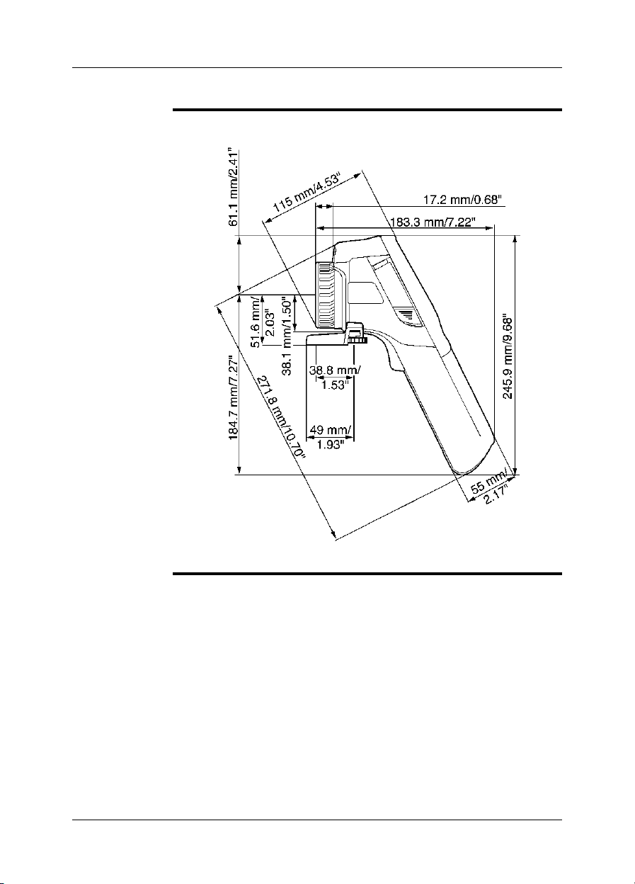
25 – Dimensional drawings
25.4 Camera dimensions, side view (2)
Figure
T638773;a1
68 Publ. No. T559597 Rev. a554 – ENGLISH (EN) – September 27, 2011

25.5 Camera dimensions, side view (3)
25 – Dimensional drawings
Figure
T638774;a1
Publ. No. T559597 Rev. a554 – ENGLISH (EN) – September 27, 2011 69
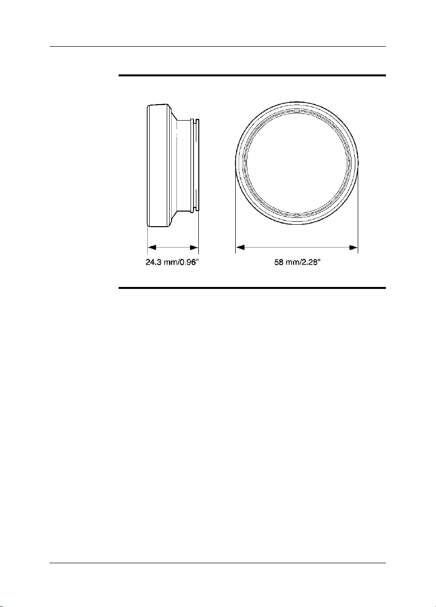
25 – Dimensional drawings
25.6 Infrared lens (30 mm/15°)
Figure
10762503;a1
70 Publ. No. T559597 Rev. a554 – ENGLISH (EN) – September 27, 2011

25.7 Infrared lens (10 mm/45°)
25 – Dimensional drawings
Figure
10762403;a1
Publ. No. T559597 Rev. a554 – ENGLISH (EN) – September 27, 2011 71

25 – Dimensional drawings
25.8 Battery (1)
Figure
NOTE
T638782;a1
Use a clean, drycloth to removeany water ormoisture on the battery beforeyou install
it.
72 Publ. No. T559597 Rev. a554 – ENGLISH (EN) – September 27, 2011
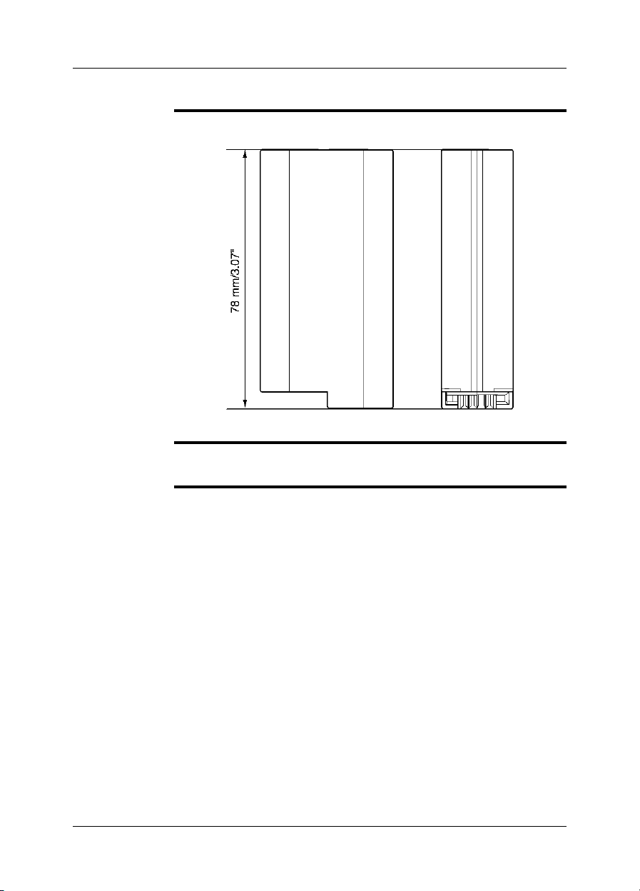
25.9 Battery (2)
25 – Dimensional drawings
Figure
NOTE
T638783;a1
Use a clean, drycloth to removeany water ormoisture on the battery beforeyou install
it.
Publ. No. T559597 Rev. a554 – ENGLISH (EN) – September 27, 2011 73
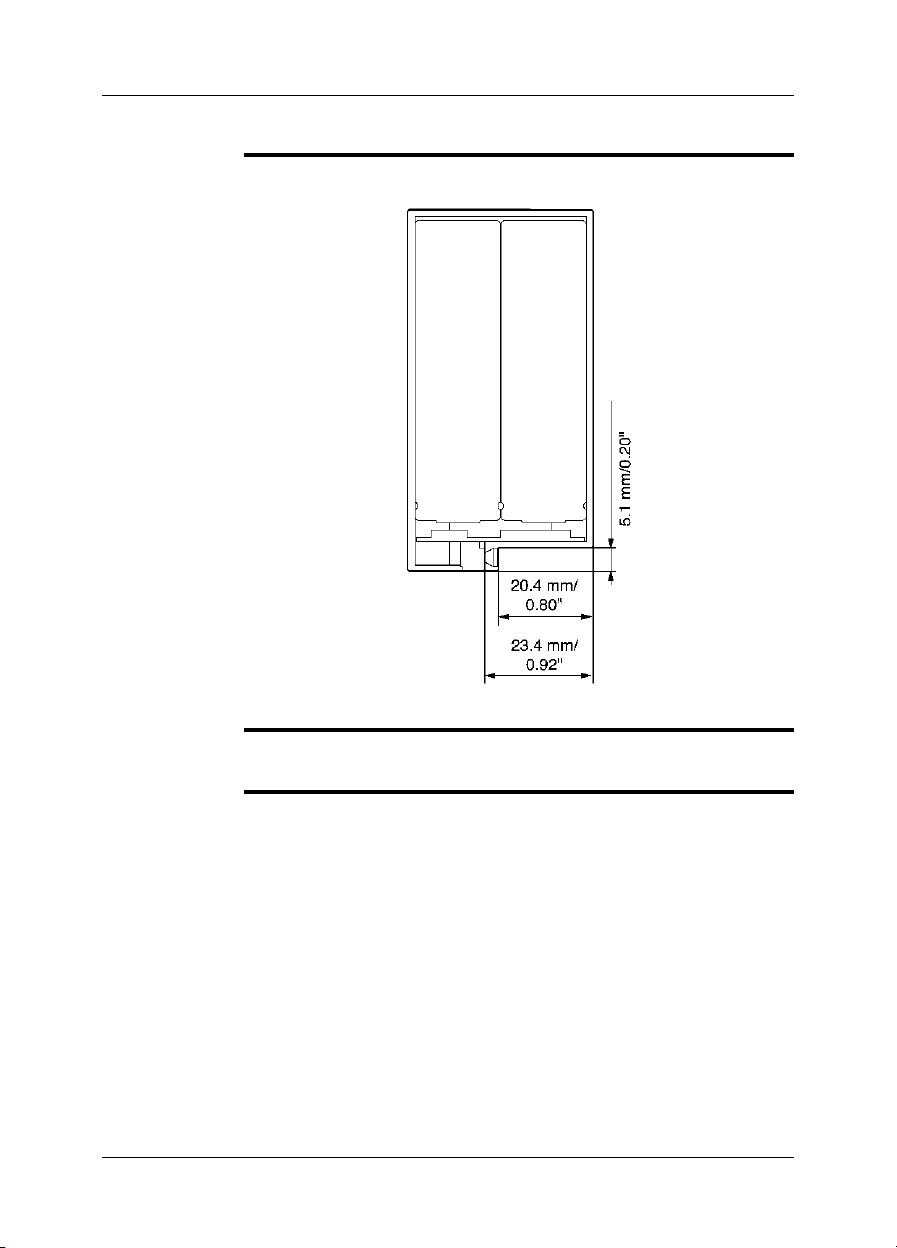
25 – Dimensional drawings
25.10 Battery (3)
Figure
NOTE
T638784;a1
Use a clean, drycloth to removeany water ormoisture on the battery beforeyou install
it.
74 Publ. No. T559597 Rev. a554 – ENGLISH (EN) – September 27, 2011
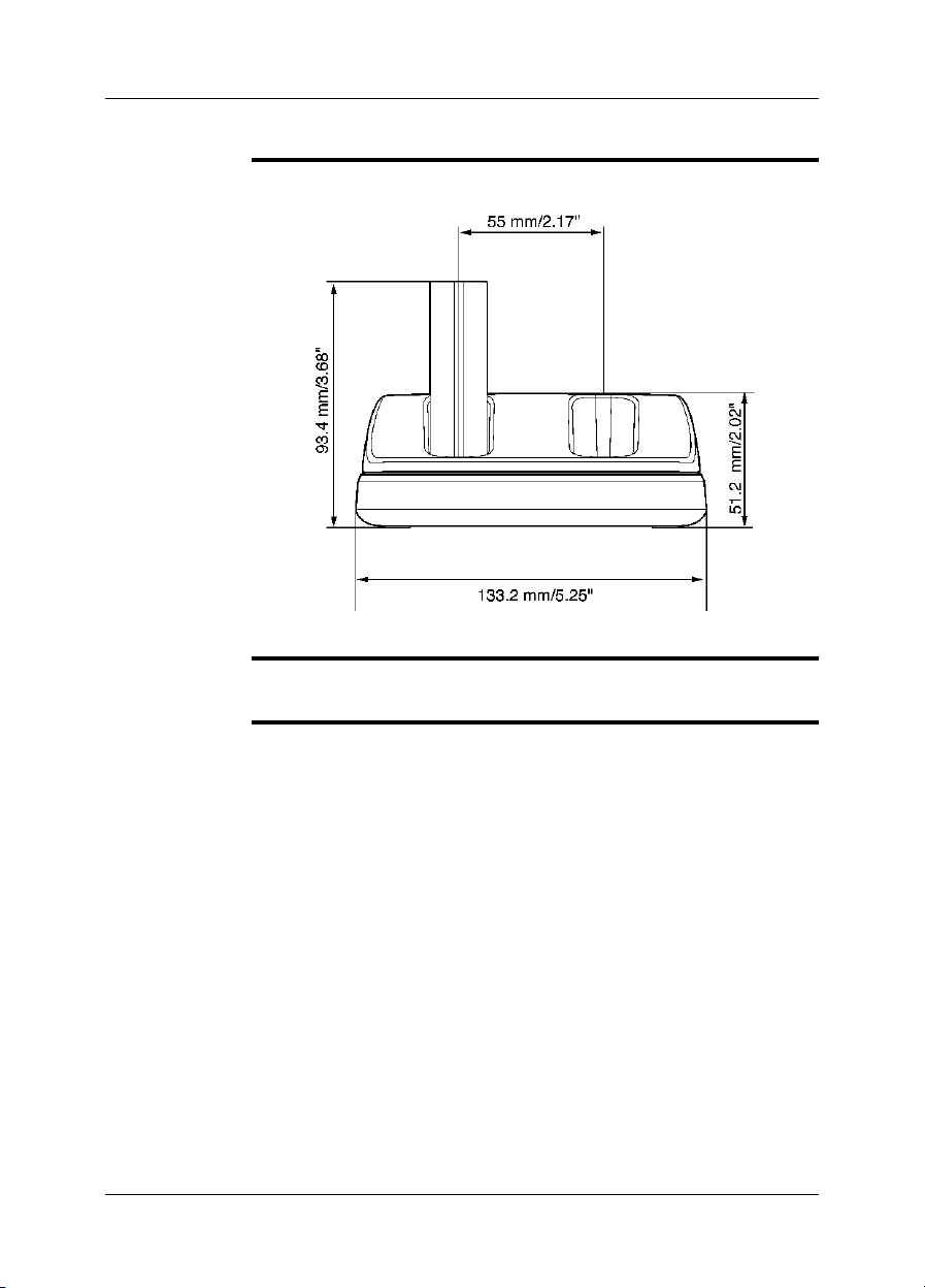
25.11 Battery charger (1)
25 – Dimensional drawings
Figure
NOTE
T638767;a1
Use a clean, dry cloth to remove any water or moisture on the battery before you put
it in the battery charger.
Publ. No. T559597 Rev. a554 – ENGLISH (EN) – September 27, 2011 75

25 – Dimensional drawings
25.12 Battery charger (2)
Figure
NOTE
T638768;a1
Use a clean, dry cloth to remove any water or moisture on the battery before you put
it in the battery charger.
76 Publ. No. T559597 Rev. a554 – ENGLISH (EN) – September 27, 2011

25.13 Battery charger (3)
25 – Dimensional drawings
Figure
NOTE
T638769;a1
Use a clean, dry cloth to remove any water or moisture on the battery before you put
it in the battery charger.
Publ. No. T559597 Rev. a554 – ENGLISH (EN) – September 27, 2011 77

25 – Dimensional drawings
25.14 Battery charger (4)
Figure
NOTE
T638770;a1
Use a clean, dry cloth to remove any water or moisture on the battery before you put
it in the battery charger.
78 Publ. No. T559597 Rev. a554 – ENGLISH (EN) – September 27, 2011

26 Application examples
26.1 Moisture & water damage
General
NOTE
Figure
It is often possible to detect moisture and water damage in a house by using an infrared camera. This ispartly becausethe damaged area has adifferent heat conduction property and partly because it has a differentthermal capacity to storeheat than
the surrounding material.
Many factors can come into play as to how moisture or water damage will appear in
an infrared image.
For example,heating and coolingof these parts takes placeat different ratesdepending on the material and the time of day. For this reason, it is important that other
methods are used as well to check for moisture or water damage.
The imagebelow shows extensive waterdamage on anexternalwall where thewater
has penetrated the outer facing because of an incorrectly installed window ledge.
10739503;a1
Publ. No. T559597 Rev. a554 – ENGLISH (EN) – September 27, 2011 79

26 – Application examples
26.2 Faulty contact in socket
General
NOTE
Figure
Depending on the type of connection a socket has, an improperly connected wire
can result in local temperature increase. This temperature increase is caused by the
reduced contact area between the connection point of the incoming wire and the
socket , and can result in an electrical fire.
A socket’s construction may differ dramatically from one manufacturer to another.
For this reason, different faults in a socket can lead to the same typical appearance
in an infrared image.
Local temperature increase can also result from improper contact between wire and
socket, or from difference in load.
The image below shows aconnection ofa cable to a socket where improper contact
in the connection has resulted in local temperature increase.
10739603;a1
80 Publ. No. T559597 Rev. a554 – ENGLISH (EN) – September 27, 2011

26.3 Oxidized socket
26 – Application examples
General
NOTE
Figure
Depending on the typeof socket andthe environment in which thesocket is installed,
oxides may occur on the socket's contact surfaces. These oxides can lead to locally
increased resistance when the socket is loaded, which can be seen in an infrared
image as local temperature increase.
A socket’s construction may differ dramatically from one manufacturer to another.
For this reason, different faults in a socket can lead to the same typical appearance
in an infrared image.
Local temperature increase can also result from improper contact between a wire
and socket, or from difference in load.
The image below shows a series of fuses where one fuse has a raised temperature
on the contact surfaces against the fuse holder. Because of the fuse holder’s blank
metal, the temperature increase is not visible there, while it is visible on the fuse’s
ceramic material.
10739703;a1
Publ. No. T559597 Rev. a554 – ENGLISH (EN) – September 27, 2011 81

26 – Application examples
26.4 Insulation deficiencies
General
NOTE
Figure
Insulation deficiencies may result from insulation losing volume over the course of
time and thereby not entirely filling the cavity in a frame wall.
An infrared camera allowsyou to seethese insulation deficienciesbecause they either
have a different heat conduction property than sections with correctly installed insulation, and/or show the area where air is penetrating the frame of the building.
When you are inspecting a building, the temperature difference between the inside
and outside should be at least 10°C (18°F). Studs, water pipes, concrete columns,
and similar components may resemble an insulation deficiency in an infrared image.
Minor differences may also occur naturally.
In the image below, insulation in the roof framing is lacking.. Due to the absence of
insulation, air has forcedits way into the roof structure, whichthus takes on a different
characteristic appearance in the infrared image.
10739803;a1
82 Publ. No. T559597 Rev. a554 – ENGLISH (EN) – September 27, 2011

26.5 Draft
26 – Application examples
General
NOTE
Figure
Draft can be found under baseboards, around door and window casings, and above
ceiling trim. This type of draft is often possible to see with an infrared camera, as a
cooler airstream cools down the surrounding surface.
When youare investigating draftin a house,there should besub-atmosphericpressure
in the house. Close all doors, windows, and ventilation ducts, and allow the kitchen
fan to run for a while before you take the infrared images.
An infrared image of draft often shows a typical stream pattern. You can see this
stream pattern clearly in the picture below.
Also keep in mind that drafts can be concealed by heat from floor heating circuits.
The image below shows a ceiling hatch where faulty installation has resulted in a
strong draft.
10739903;a1
Publ. No. T559597 Rev. a554 – ENGLISH (EN) – September 27, 2011 83

27 Introduction to building
thermography
27.1 Disclaimer
27.1.1 Copyright notice
Some sectionsand/or images appearing in this chapter are copyrighted tothe following organizations and companies:
■ FORMAS—The Swedish Research Council for Environment, Agricultural Sciences
and Spatial Planning, Stockholm, Sweden
■ ITC—Infrared Training Center, Boston, MA, United States
■ Stockton Infrared Thermographic Services, Inc., Randleman, NC, United States
■ Professional Investigative Engineers, Westminster, CO, United States
■ United Kingdom Thermography Association (UKTA)
27.1.2 Training & certification
Carrying out building thermography inspections requires substantial training
and experience, and may require certification from a national or regional standardization body. This section is provided only as an introduction to building
thermography. The user is strongly recommended to attend relevant training
courses.
For more information about infrared training, visit the following website:
http://www.infraredtraining.com
27.1.3 National or regional building codes
The commented building structures in this chapter may differ in construction from
country to country. For more information about construction details and standards
of procedure, always consult national or regional building codes.
27.2 Important note
All camera functions and features that are described in this section may not be supported by your particular camera configuration.
84 Publ. No. T559597 Rev. a554 – ENGLISH (EN) – September 27, 2011
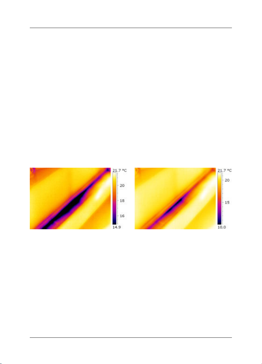
27 – Introduction to building thermography
27.3 Typical field investigations
27.3.1 Guidelines
As will be noted in subsequent sections there are a number of general guidelines the
user should take heed of when carrying out building thermography inspection. This
section gives a summary of these guidelines.
27.3.1.1 General guidelines
■ The emissivity of the majority of building materials fall between 0.85 and 0.95.
Setting the emissivity value in the camera to 0.90 can be regarded as a good
starting point.
■ An infrared inspection alone should never be used as a decision point for further
actions. Always verify suspicions and findings using other methods, such as construction drawings, moisture meters, humidity & temperature datalogging, tracer
gas testing etc.
■ Change level and span to thermallytune theinfrared image and reveal more details.
The figurebelow shows the difference between a thermally untuned and a thermally
tuned infrared image.
10552103;a2
Figure 27.1 LEFT: A thermally untuned infrared image; RIGHT: A thermally tuned infrared image, after
having changed level and span.
27.3.1.2 Guidelines for moisture detection, mold detection & detection of water damages
■ Building defects related to moisture and water damages may only show up when
heat has been applied to the surface, e.g. from the sun.
■ The presence of water changes the thermal conductivity and the thermal mass of
the building material. It may also change the surfacetemperature of building material due to evaporative cooling. Thermal conductivity is a material’s abilityto conduct
heat, while thermal mass is its ability to store heat.
Publ. No. T559597 Rev. a554 – ENGLISH (EN) – September 27, 2011 85

27 – Introduction to building thermography
■ Infrared inspection does not directly detect the presence of mold, rather it may be
used to find moisture where mold may develop or has already developed. Mold
requires temperatures between +4°C to +38°C (+40°F to +100°F), nutrients and
moisture to grow. Humidity levels above 50% can provide sufficient moisture to
enable mold to grow.
10556003;a1
Figure 27.2 Microscopic view of mold spore
27.3.1.3 Guidelines for detection of air infiltration & insulation deficiencies
■ For very accurate camera measurements, take measurements of the temperature
and enter this value in the camera.
■ It is recommended that there is a difference in pressure between the outside and
the inside of the building structure. This facilitates theanalysis of the infrared images
and reveals deficiencies that would not be visible otherwise. Although a negative
pressure of between 10 and 50 Pa is recommended, carrying out the inspection
at a lower negative pressure may be acceptable. To do this, close all windows,
doors and ventilation ducts and then run the kitchen exhaust fan for some time to
reach a negative pressure of 5–10 Pa (applies to residential houses only).
■ A difference in temperature between the inside and the outside of 10–15°C(18–27°F)
is recommended.Inspections can be carried out at a lower temperature difference,
but will make the analysis of the infrared images somewhat more difficult.
■ Avoid direct sunlight on a part of a building structure—e.g. a façade—that is to be
inspected from the inside. The sunlight will heat the façade which will equalize the
temperature differenceson theinside and mask deficiencies in the building structure.
Spring seasons with low nighttime temperatures (±0°C (+32°F)) and high daytime
temperatures (+14°C (+57°F)) are especially risky.
86 Publ. No. T559597 Rev. a554 – ENGLISH (EN) – September 27, 2011

27 – Introduction to building thermography
27.3.2 About moisture detection
Moisture in a building structure can originate from several different sources, e.g.:
■ External leaks, such as floods, leaking fire hydrants etc.
■ Internal leaks, such as freshwater piping, waste water piping etc.
■ Condensation, which is humidity in the air falling out as liquid water due to conden-
sation on cold surfaces.
■ Building moisture, which is any moisture in the building material prior to erecting
the building structure.
■ Water remaining from firefighting.
As a non-destructive detection method, using an infrared camera has a number of
advantages over other methods, and a few disadvantages:
DisadvantageAdvantage
The method is quick.
■
The methodis a non-intrusivemeansof investi-
■
gation.
The method does not require relocation of the
■
occupants.
The method features an illustrative visual pre-
■
sentation of findings.
The method confirms failure points and mois-
■
ture migration paths.
The method only detects surface temperature
■
differentials and can not see through walls.
The methodcan not detectsubsurfacedamage,
■
i.e. mold or structural damage.
27.3.3 Moisture detection (1): Low-slope commercial roofs
27.3.3.1 General information
Low-slope commercial roofing is one of the most common roof types for industrial
building, such as warehouses, industrial plants, machinery shops etc. Its major advantages over a pitched roof is the lower cost in material and building. However, due
to its design where snow and ice will not fall off by itself—as is the case for the majority of pitched roofs—it must be strongly built to support the accumulated weight of
both roof structure and any snow, ice and rain.
Although a basic understanding of the construction of low-slope commercial roofs is
desirable whencarrying outa roof thermography inspection, expert knowledge is not
necessary. There is a large number of different design principles for low-slope commercial roofs—bothwhen itcomes tomaterial anddesign—and itwould beimpossible
for the infrared inspection person to know them all. If additional information about a
certain roof is needed, the architect or contractor of the building can usually supply
the relevant information.
Common causesof rooffailure areoutlined in the table below (from SPIE Thermosense
Proceedings Vol. 371 (1982), p. 177).
Publ. No. T559597 Rev. a554 – ENGLISH (EN) – September 27, 2011 87

27 – Introduction to building thermography
%Cause
47.6Poor workmanship
2.6Roof traffic
16.7Poor design
7.8Trapped moisture
8.0Materials
8.4Age & weathering
Potential leak locations include the following:
■ Flashing
■ Drains
■ Penetrations
■ Seams
■ Blisters
27.3.3.2 Safety precautions
■ Recommend a minimum of two people on a roof, preferably three or more.
■ Inspect the underside of the roof for structural integrity prior to walking on it.
■ Avoid stepping on blisters that are common on built up bitumen and gravel roofs.
■ Have a cell phone or radio available in case of emergency.
■ Inform local police and plant security prior to doing nighttime roof survey.
88 Publ. No. T559597 Rev. a554 – ENGLISH (EN) – September 27, 2011
 Loading...