


Installation
Manual
FC-Series
FC-Series O
FC-Series ID
427-0089-00-12 Version 160 March 2019
Find Quality Products Online at: sales@GlobalTestSupply.com
www.GlobalTestSupply.com
This document does not contain any export-controlled information.

© 2019 FLIR Systems, Inc. All rights reserved worldwide. No parts of this manual, in whole or in part, may be
copied, photocopied, translated, or transmitted to any electronic medium or machine readable form without the
prior written permission of FLIR Systems, Inc.
Names and marks appearing on the products herein are either registered trademarks or trademarks of FLIR
Systems, Inc. and/or its subsidiaries. All other trademarks, trade names, or company names referenced herein are
used for identification only and are the property of their respective owners.
This product is protected by patents, design patents, patents pending, or design patents pending.
The contents of this document are subject to change without notice.
For additional information visit www.flir.com or write to FLIR Systems, Inc.
FLIR Systems, Inc.
6769 Hollister Avenue
Goleta, CA 93117
Support: https://www.flir.com/support-center/support-hq/
Important Instructions and Notices to the User:
This device complies with part 15 of the FCC Rules. Operation is subject to the following two conditions: (1) This
device may not cause harmful interference, and (2) this device must accept any interference received, including
interference that may cause undesired operation.
Modification of this device without the express authorization of FLIR Systems, Inc. may void the user’s authority
under FCC rules to operate this device.
Note 1: This equipment has been tested and found to comply with the limits for a Class A digital device, pursuant to
part 15 of the FCC Rules. These limits are designed to provide reasonable protection against harmful interference
when the equipment is operated in a commercial environment. This equipment generates, uses, and can radiate
radio frequency energy and, if not installed and used in accordance with the instruction manual, may cause harmful
interference to radio communications. Operation of this equipment in a residential area is likely to cause harmful
interference in which case the user will be required to correct the interference at the user’s own expense.
Note 2:
If this equipment came with shielded cables, it was tested for compliance with the FCC limits for
a Class A digital device using shielded cables and therefore shielded cables must be used with the
device
Industry Canada Notice:
This Class A digital apparatus complies with Canadian ICES-003.
Avis d’Industrie Canada:
Cet appareil numérique de la classe A est conforme à la norme NMB-003 du Canada.
Proper Disposal of Electrical and Electronic Equipment (EEE)
The European Union (EU) has enacted Waste Electrical and Electronic Equipment Directive 2002/
96/EC (WEEE), which aims to prevent EEE waste from arising; to encourage reuse, recycling, and
recovery of EEE waste; and to promote environmental responsibility.
In accordance with these regulations, all EEE products labeled with the “crossed out wheeled bin”
either on the product itself or in the product literature must not be disposed of in regular rubbish bins,
mixed with regular household or other commercial waste, or by other regular municipal waste
collection means. Instead, and in order to prevent possible harm to the environment or human
health, all EEE products (including any cables that came with the product) should be responsibly
discarded or recycled.
To identify a responsible disposal method nearby, please contact the local waste collection or recycling service, the
original place of purchase or product supplier, or the responsible government authority in the area. Business users
should contact their supplier or refer to their purchase contract.
Document History
Version Date Comment
100 July 2016 Initial Release
110 August 2016 User Interface Updates
120 January 2017 Setup Temperature/GPIO User Interface Update
130 March 2017 Added support for IEEE 802.1x authentication, Field Service log download, and IOI analytics interface
140 August 2017 Initial release of FC-Series O
150 March 2018 Updated password management, simplified IR graphical user interface
160 March 2019 V2.04.P06
427-0089-00-12 Version 160
This document does not contain any export-controlled information.
Find Quality Products Online at: sales@GlobalTestSupply.com
www.GlobalTestSupply.com

Table of Contents
Table of Contents
Camera Installation
1.1 Warnings and Cautions ............................................................................................... 5
1.2 References .................................................................................................................. 5
1.3 Installation Overview ................................................................................................... 6
1.3.1 Camera Connection Options .............................................................................. 6
1.3.2 Camera Accessories .......................................................................................... 7
1.3.3 Supplied Components ........................................................................................ 8
1.3.4 Additional Supplies ............................................................................................. 8
1.3.5 Camera Placement ............................................................................................. 8
1.3.6 Camera Mounting for Rear Cable Access .......................................................... 9
1.3.7 Camera Mounting with Concealed Cable Wall Mount ...................................... 11
1.3.8 Sunshield .......................................................................................................... 12
1.3.9 Removing the Cover ......................................................................................... 12
1.4 Camera Connections ................................................................................................. 13
1.4.1 Installing the microSD Card .............................................................................. 13
1.4.2 Bench Testing .................................................................................................. 14
1.4.3 Analog Video Connections ............................................................................... 14
1.4.4 Connecting Power ............................................................................................ 14
1.4.5 GPIO Connections ........................................................................................... 15
1.4.6 Ethernet ............................................................................................................ 16
1.4.7 Camera Grounding ........................................................................................... 16
1.4.8 Rear Access Cable Gland Sealing ................................................................... 17
1.5 Concealed Cable Mount Accessory .......................................................................... 18
1.6 Camera specifications ............................................................................................... 20
Basic Operation and Configuration
2.1 IP Camera, ONVIF Profile S Compliant .................................................................... 22
2.2 Camera Bench Test .................................................................................................. 22
2.3 Set IP Address using the FLIR Discovery Network Assistant (DNA) ........................ 22
2.3.1 Log in to the Camera Web Page ...................................................................... 23
2.3.2 Live Video Page ............................................................................................... 24
2.4 Basic Camera Configuration ..................................................................................... 27
2.4.1 Setup Menu ...................................................................................................... 27
2.4.2 Server Menu ..................................................................................................... 28
2.5 Thermal Imaging Overview ....................................................................................... 37
2.6 Maintenance and Troubleshooting Tips .................................................................... 38
427-0089-00-12 Version 160 March 2019 3
Find Quality Products Online at: sales@GlobalTestSupply.com
www.GlobalTestSupply.com
This document does not contain any export-controlled information.
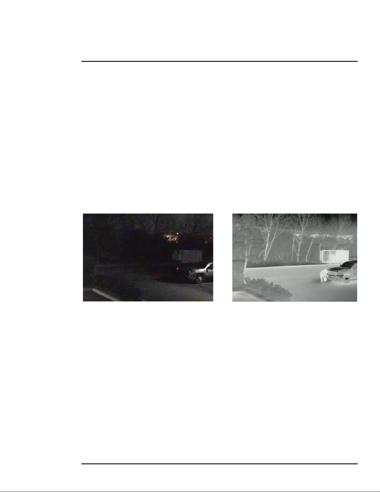
Table of Contents
Advanced Configuration
3.1 Setup Menu ............................................................................................................... 42
3.1.1 Temperature Page ............................................................................................43
3.1.2 Video Setup ...................................................................................................... 44
3.1.3 Thermal Image Setup ....................................................................................... 47
3.1.4 Video Analytics Setup—FC-Series ID only ....................................................... 49
3.2 Maintenance Menu .................................................................................................... 54
3.2.1 Sensor Menu .................................................................................................... 55
3.2.2 Files Menu ........................................................................................................ 66
3.2.3 Product Info Menu ............................................................................................ 70
3.3 Restoring the Factory Settings .................................................................................. 70
Image from a standard camera in low light
427-0089-00-12 Version 160 March 2019 4
Find Quality Products Online at: sales@GlobalTestSupply.com
www.GlobalTestSupply.com
This document does not contain any export-controlled information.
Image from a thermal camera in the same
conditions

1
Camera Installation
This manual describes the installation and initial configuration of the FC-Series thermal camera. The
FC-Series ID and the FC-Series O are based on identical hardware. The FC-Series ID camera has
software installed providing for on-board video analytics: setting of detection regions, trip lines, and
classification of detected objects. Refer to Video Analytics Setup—FC-Series ID only, pg. 49.
If help is needed during the installation process, contact the local FLIR service representative or
contact support at: https://www.flir.com/support-center/support-hq/. All installers and integrators are
encouraged to take advantage of the training offered by FLIR; visit
https://www.flir.com/support-center/training/ for more information.
This manual includes the following topics:
• Installation overview
• Mounting the camera and its components
• Connecting the electronics
• Bench testing the camera
• Basic configuration and operation of the camera
• Camera Specifications
For safety, and to achieve the highest levels of performance from the FC-Series camera system,
always follow the warnings and cautions in this manual when handling and operating the camera.
1.1 Warnings and Cautions
Warning!
If mounting the FC-Series camera on a pole, tower or any elevated location, use industry standard
safe practices to avoid injuries.
Caution!
Except as described in this manual, do not open the FC-Series camera for any reason. Damage to
the camera can occur as the result of careless handling or electrostatic discharge (ESD). Always
handle the camera with care to avoid damage to electrostatic-sensitive components.
Prior to making any connections, ensure the power supply or circuit breaker is switched off.
Be careful not to leave fingerprints on the camera’s infrared optics.
Operating the camera outside of the specified input voltage range or the specified operating
temperature range can cause permanent damage.
1.2 References
FLIR Doc # 427-00XX-YY-41 FC-Series Interconnect Document provides further details regarding
mechanical dimensions and mounting for the FC-Series camera.
Documents are available from the FLIR website.
427-0089-00-12 Version 160 March 2019 5
Find Quality Products Online at: sales@GlobalTestSupply.com
www.GlobalTestSupply.com
This document does not contain any export-controlled information.

Camera Installation
1.3 Installation Overview
The FC-Series camera is an infrared thermal imaging camera intended for outdoor security
applications, and can be installed in a fixed location or on a pan/tilt mechanism. The camera is
intended to be mounted on a medium-duty fixed pedestal mount or wall mount commonly used in the
security industry. The camera mount must support up to 5.4 lbs (2.5 kg).
Cables may exit from the back of the camera housing through the
supplied cable gland or from the bottom of the camera housing when
using the concealed cable wall mount (sold separately). A cable gland
plug is supplied for the rear of the camera housing when cables are
routed using the concealed cable wall mount.
1.3.1 Camera Connection Options
The camera can be installed with an analog or digital (IP) video output (or both). Analog video will
require a connection to a video monitor or an analog video matrix switch. The camera can be
powered using Power over Ethernet Plus (PoE+) or with a conventional 24 Vac or 24 Vdc power
supply. For a PoE+ connection, an accessory PoE+ power supply (PN 4132391, also called a PoE+
injector) is available if the camera is not connected to a PoE+ switch. The maximum Ethernet cable
run is 100 meters including the PoE+ power supply. In installations using PoE+ power and IP video,
only a single Ethernet cable from the camera is required.
In installations using analog video and conventional power (24 Vac is commonly used in many
installations), an RG59U coaxial cable and a three-conductor power cable are installed. It is
recommended an Ethernet cable should also be installed for camera configuration, operation and
troubleshooting. For example, if the camera is mounted on a pole, an Ethernet cable should run at
least to the bottom of the pole, so a laptop could be temporarily connected directly to the camera.
The FC-Series camera does not support serial communications.
Network Security
The camera supports IEEE 802.1x authentication when connected to a network supporting the
following requirements:
• Network device (Authenticator) such as an Ethernet switch configured with 802.1x
• Authentication server supporting TLS
Refer to IEEE 802.1X Security, pg. 29 for information on how to configure the LAN settings.
General Purpose Input/Output (GPIO)
The camera can receive a single input signal and can provide a single output signal. By default the
signals are configured for normally open alarm switch circuits. Refer to GPIO Connections, pg. 15.
Input Signal—When an external alarm device closes a switch to complete the circuit for the
camera, an input alarm is generated by the GPIO for the Alarm Manager.
Output Signal—When an output alarm is generated by the Alarm Manager for the GPIO, the
camera closes its internal switch to complete the circuit for the receiving device.
427-0089-00-12 Version 160 March 2019 6
Find Quality Products Online at: sales@GlobalTestSupply.com
www.GlobalTestSupply.com
This document does not contain any export-controlled information.

Camera Installation
PoE+ Power Supplies
With PoE+, camera power is delivered to the camera over the Ethernet cable via the camera’s
standard RJ-45 Ethernet connector. The FC-Series camera is a Powered Device compliant with the
IEEE 802.3at-2009 standard, known as PoE+ or PoE Plus. The FC-Series camera is also backward
compatible with the older IEEE 802.3af-2003 standard.
When connected to Power Sourcing Equipment compliant with the earlier, lower power IEEE
802.3af-2003 standard, the limited power available to the FC-Series will typically prevent the
formation of frost and ice. However, the limited power available from 802.3af-2003 may not fully
achieve the camera’s stated specification of de-icing 6 mm of ice from cold start. In all other ways the
camera will operate normally with Ethernet Powered Sourcing Equipment compliant to either IEEE
PoE standard.
Supplemental Lens Heater
The supplemental lens heater is intended to provide lens de-fogging and de-icing in the event of:
• A power interruption which disables the camera for an extended period, and
• Freezing rain which fully covers the lens and obstructs the image.
The FC-Series cameras with lens windows (13 mm, 19 mm, 35 mm) are shipped from the factory
with the supplemental lens heater on. The lens heater is configured to dynamically maintain the
camera window at a constant temperature.
The lens heater may be turned on manually from the Live Video web page (De-Ice button). Refer to
Web Control Panel, pg. 25. The heater, when turned on manually, will run for approximately 2 hours
unless turned off either by the user (De-Ice button) or the thermostat control.
FC-Series cameras with a 60 mm or a 75 mm lens are shipped from the factory with the
supplemental lens heater off. These cameras require the de-ice kit accessory for installations that
require using the supplemental lens heater. After installing the de-ice kit, contact FLIR Technical
Support for configuration instructions for the specific installation.
Note
The 60 mm or 75 mm lenses are not thermally conductive. The de-ice kit provides a lens cover
that will conduct heat to keep the lens free of ice or frost.
1.3.2 Camera Accessories
The following accessories are available for purchase from FLIR Systems, Inc.
• PoE+ power supply (PN 4132391) - For powering a single FC-Series camera using PoE+. In
addition to PoE+ power and communications, the power supply provides surge protection. It
complies with IEEE 802.3at and is backward compatible with the IEEE802.3af standard.
• Concealed Cable Wall Mount (PN 4129742) - Includes camera mount
gasket and hex wrench for adjusting the ball joint controlling the
camera’s view angle. The FC-Series camera is attached to the
mounting arm using the four M5 threaded bottom mounting holes. A
cable gland plug is supplied with the camera for the rear of the camera
housing when cables are routed using the concealed cable accessory.
Refer to Camera Mounting with Concealed Cable Wall Mount, pg. 11.
Concealed Cable
Wall Mount
427-0089-00-12 Version 160 March 2019 7
Find Quality Products Online at: sales@GlobalTestSupply.com
www.GlobalTestSupply.com
This document does not contain any export-controlled information.

Camera Installation
• Pole Mount Adapter Kit (PN 4132982) - Adapter kit that allows the Concealed Cable Wall Mount
to be mounted to a pole (75 mm [3 in] min to 180 mm [7 in];
larger pole diameter requires use of customer supplied band clamps)
• FC-Series De-Ice Kit (PN 421-0056-00 for 60 mm lens, and PN 421-0057-00 for 75 mm lens)
The 60 mm and 75 mm lenses are not thermally conductive. The de-ice-kit provides a lens cover
that will conduct heat to keep the lens free of ice or frost while also protecting the lens in salt or
other harsh environments. Refer to Supplemental Lens Heater, pg. 7.
1.3.3 Supplied Components
The FC-Series camera package includes these standard components:
• Fixed Camera Unit with sun shield and installed cable gland
• Cable gland plug and gland inserts for sealing camera housing
• Power terminal block plug (installed)
• Accessory terminal block plugs (installed)
• Tools: 3 mm hex wrench (T-Handle), small blade screwdriver
1.3.4 Additional Supplies
The installer will need to supply the following items as required (specific to the installation).
• Optional customer supplied microSD card (up to 64 GB) provides local storage of image files
through power cycles.
• Power supply, 18 Vac to 32 Vac or 11 Vdc to 32 Vdc, if not using PoE power for system power.
• Power cable, 3-conductor, shielded, gauge determined by cable length and supply voltage,
if used for system power
• Accessory cable 6-conductor for GPIO (optional)
• PoE+ power supply or PoE+ switch, if used for system power. Note that the camera will operate
normally with PoE, but lens heaters may not operate to specification in cold environments.
• Cat5e or Cat6 Ethernet cable for digital video and/or PoE+ for system power
• Coaxial RG59U cables (BNC connector at the camera end) for analog video
• Camera grounding strap, camera mount, electrical hardware, connectors, and tools
Be sure to use cables that fit in the cable gland holes, as described below. Refer to Rear Access
Cable Gland Sealing, pg. 17 for more information.
1.3.5 Camera Placement
The FC-Series camera may be mounted upright, either on top of the mounting surface. or
underneath an overhanging mounting surface such as eaves or an awning. The camera may also be
mounted sideways in order to view a scene such as along a fence line or corridor. Adhere to all local
and industry standards, codes, and best practices.
Although the FC-Series O camera does not have on-board video analytics, many video
management systems and video encoders analyze the video signals to send alarm notifications
based on customized rules. Several types of third-party Video Management Systems (VMS) are
427-0089-00-12 Version 160 March 2019 8
Find Quality Products Online at: sales@GlobalTestSupply.com
www.GlobalTestSupply.com
This document does not contain any export-controlled information.

Camera Installation
supported by FLIR IP cameras. Because these systems tend to evolve and change over time,
contact the local FLIR representative or FLIR Technical Support for information.
α
Camera mounted upright
For installations with multiple FC-Series ID cameras with on-board video analytics, the fields of view
of cameras should overlap in order to remove all dead zones in which a camera cannot see a target
“head to toe”. The camera’s on-board analytics must be calibrated to detect targets. Refer to Video
Analytics Setup—FC-Series ID only, pg. 49.
• Install the camera at a height of approximately 4 m (13 ft) or more.
• Typically direct the camera towards the ground with a tilt angle α within a range of 45° to 60°
while ensuring the field of view includes as little of the skyline as possible.
• Ensure that cameras are mounted on stable mounts with minimal vibrations and maximal
resistance to wind.
• The tilt angle (
Typically direct the camera towards the ground with a tilt angle α of 45° to 60°. Include as little
skyline as possible in the field of view.
1.3.6 Camera Mounting for Rear Cable Access
The FC-Series camera can be secured to the mount with two in-line 1/4-20 threaded fasteners on
the top or bottom of the camera. Alternatively the camera can be mounted with four M5 x 0.8
threaded fasteners to the bottom of the camera. Use Loctite 222 low strength threadlocker for the
top mount fasteners (can be used with the bottom mount fasteners also). Refer to the FC-Series ICD
for additional information.
α) is the angle between vertical and the center of the camera field of view.
427-0089-00-12 Version 160 March 2019 9
Find Quality Products Online at: sales@GlobalTestSupply.com
www.GlobalTestSupply.com
This document does not contain any export-controlled information.

Camera Installation
If using two 1/4-20 fasteners in the center of base, the maximum depth of the fastener should not
exceed 12.5 mm (0.5 in). If using four M5 x 0.8 fasteners, the maximum depth of the fastener should
not exceed 10.0 mm (0.4 in).
Figure 1-1: FC-Series Camera Bottom Mounting Holes
Figure 1-2: Top Mounting Holes
If using two 1/4-20 fasteners in the center of top, the maximum depth of the fastener should not
exceed 12.5 mm (0.5 in). If the camera is mounted using the top of the camera, the sunshield must
be removed.
427-0089-00-12 Version 160 March 2019 10
Find Quality Products Online at: sales@GlobalTestSupply.com
www.GlobalTestSupply.com
This document does not contain any export-controlled information.

Camera Installation
As the diagram below indicates, be sure to allow adequate space for cable egress behind the gland.
This requirement may vary, depending on the installation. Maintain the bend radius per the
recommendation of the cable manufacturer. The typical cable bend radius is 50-75 mm (2-3 in).
Figure 1-3: Rear Cable Bend Radius
1.3.7 Camera Mounting with Concealed Cable Wall Mount
The FC-Series camera can be secured to the optional Concealed Cable Wall Mount with four M5 x
0.8 threaded fasteners to the bottom of the camera. Use Loctite 222 low strength threadlocker for
the mount fasteners. Refer to Concealed Cable Mount Accessory, pg. 18 for additional information.
Figure 1-4: FC-Series Installed with Concealed Cable Wall
Mount and Pole Adapter kit
427-0089-00-12 Version 160 March 2019 11
Find Quality Products Online at: sales@GlobalTestSupply.com
www.GlobalTestSupply.com
This document does not contain any export-controlled information.

Camera Installation
1.3.8 Sunshield
The camera includes a sunshield which should be used for any installation where the camera is
exposed to direct sunlight or precipitation, If the camera is mounted with the top mounting holes, the
sunshield is not used. Depending on the needs of the installation, the sunshield can be positioned in
the neutral (middle) position, or slightly forward or rearward.To change the position of the sunshield,
temporarily loosen the three 3 mm hex screws on top, slide the sunshield forward or backward, and
re-tighten the screws.
Sunshield mounting screws (x3)
Figure 1-5: Sunshield Mounting
1.3.9 Removing the Cover
In order to access the electrical
connections and install the cables, it is
necessary to temporarily remove the top
cover of the camera housing. The top
cover of the camera is held in place with
four 3 mm hex screws. The screws are
accessible through slots in the
sunshield, so the sunshield does not
need to be removed from the top cover.
Cover mounting screws (x4)
Cover mounting
screws (x4)
Use a 3 mm hex key to loosen the four
captive screws, exposing the
connections inside the camera
enclosure. There is a grounding wire
connected inside the case to the top
cover, as shown. If it (or any of the
grounding wires) is temporarily
disconnected during the installation, it
must be reconnected to ensure proper
grounding of the camera.
Figure 1-6: Cover Removed (Sunshield attached)
When replacing the cover, tighten the four 3 mm hex screws to 1.8 n-m (16.0 in-lbs).
Caution!
When replacing the cover, ensure that the ground wire between the cover and the camera body is
completely inside the o-ring groove. If the wire is pinched between the cover and body the camera
is not sealed against water ingress and can be damaged.
427-0089-00-12 Version 160 March 2019 12
Find Quality Products Online at: sales@GlobalTestSupply.com
www.GlobalTestSupply.com
This document does not contain any export-controlled information.

Camera Installation
1.4 Camera Connections
Figure 1-7: Camera Connections
Refer to Table 1-1 for a description of these camera connections.
Table 1-1: FC-Series Camera Connections
Connection Purpose
1 BNC Analog video
2 3-pin Terminal Vac or Vdc power
3 microSD card
4 Ethernet PoE+ power, communications, IP video stream
5 6-pin terminal J5 General purpose I/O
6 Accessory inputs Reserved for future use
Local storage of image files up to 64 GB
(supplied by customer)
1.4.1 Installing the microSD Card
The FC-Series camera has local storage (on the camera) flash memory to store images captured as
a result of an alarm action. However, these images are lost during a reboot or power cycle. When a
427-0089-00-12 Version 160 March 2019 13
Find Quality Products Online at: sales@GlobalTestSupply.com
www.GlobalTestSupply.com
This document does not contain any export-controlled information.

Camera Installation
customer supplied microSD card (up to 64 GB) is installed, local storage is persistent through
reboots and power cycles.
Pull back cage to unlock
Lift edge to open
Insert microSD card
Close cage,
press down and
push forward to lock
1.4.2 Bench Testing
Note
If the camera is to be mounted on a pole or tower or other hard-to-reach location, it may be a good
idea to connect and operate the camera as a bench test at ground level prior to mounting the
camera in its final location.
Connect the power, Ethernet, and video, and confirm that the video can be displayed on a monitor
when the power is turned on. For configuration and basic setup information using the onboard web
server, refer to Camera Bench Test, pg. 22 for specific details.
1.4.3 Analog Video Connections
The primary analog video connection of the camera is a BNC connector. The video cable used
should be rated as RG-59/U or better to ensure a quality video signal.
Note
Insert the cables through the cable glands on the enclosure before terminating and connecting them.
In general, terminated connectors will not fit through the cable gland. If a terminated cable is
required, it is possible to make a clean and singular cut in the gland seal to install the cable.
1.4.4 Connecting Power
The camera can be powered with a conventional Vac or Vdc
power supply, rather than PoE+. Prior to making any
connections, ensure the power supply or circuit breaker is
switched off.
Table 1-2: Power Connections
1
2 Vac or Vdc (–)
3
Chassis
Vac or Vdc (+)
1
2
3
Figure 1-8: Power Connector
427-0089-00-12 Version 160 March 2019 14
Find Quality Products Online at: sales@GlobalTestSupply.com
www.GlobalTestSupply.com
This document does not contain any export-controlled information.

Camera Installation
(0.8±.20 in)
20.0±5 mm
Remove outer
jacket
(0.2±.04 in)
6.0±1 mm
Strip ends
3 Places
Power Cable
The power cable supplied by the installer must use wires that are sufficient size gauge for the supply
voltage and length of the cable run to ensure adequate current carrying capacity (18 AWG
recommended for most installations). Always follow local building/safety codes.
Note
The terminal connector for power connections will accept 16 AWG to 24 AWG wire size.
The power connector plug may be removed for cable installation. After the plug is reattached to the
board, re-tighten the screw terminals.
The camera itself does not have an on/off switch. Generally the FC-Series camera may be
connected to a circuit breaker and the circuit breaker will be used to apply or remove power to the
camera. If power is supplied to it, the camera will be powered on and operating.
1.4.5 GPIO Connections
Input Signal—When the camera senses an external
switch closure which completes the circuit between
J3 pin 1
Ethernet
J5 pins 4 and 5, an input signal is generated by the
GPIO for the Alarm Manager. Refer to Alarm
Manager, pg. 62.
Output Signal—Accessory connector J5 pins 2 and
3 connect to a switch in the camera to complete the
circuit for the receiving device. When open the
resistance between pins 2 and 3 is greater than 100 K
Figure 1-9: GPIO and Ethernet
Connectors
J5 pin 1
ohm. When closed the resistance between pins 2 and
3 is less than 200 ohm. The maximum recommended peak voltage between the pins is 6 volts. The
maximum recommended current allowed between the pins is 30 mA (0.03 A).
By default the GPIO alarm circuits are configured for normally open switches, to configure a GPIO
alarm circuit for a normally closed switch, refer to Devices Menu GPIO, pg. 60.
The terminal plug supplied for GPIO connections may be either a fast connect, spring-cage and
pierce contact, or a push-in spring contact.
The push-in spring contact accepts 20 - 24 AWG conductors. Strip conductor ends to 6 mm.
Find Quality Products Online at: sales@GlobalTestSupply.com
427-0089-00-12 Version 160 March 2019 15
www.GlobalTestSupply.com
This document does not contain any export-controlled information.

Camera Installation
The spring-cage and pierce contact accepts 22 AWG to 24 AWG, stranded conductors with a 1.6 mm
maximum diameter including insulation. Do not strip insulation from conductors.
Table 1-3: GPIO Connections - J5
Pin Connection Notes
Chassis ground
1
2
3
4
5
GPIO Out
GPIO Out
GPIO In2
(Digital ground)
GPIO In1 (+5V)
When the camera sends an output
signal, an external voltage on one
pin is applied to the other pin.
When these pins are connected
externally, the camera reads this as
an input signal.
Pin 1
Insert wires
Figure 1-10: GPIO Terminal Plug
Chassis ground
6
(Push-in spring contact)
Caution!
J5 pins 4 and 5 must not be connected to outside voltages or power sources. Pin 5 must not be
connected to chassis ground. While protection for static discharge has been placed on these pins,
care should be used when making connections to avoid damage to the camera.
1.4.6 Ethernet
Connect a shielded Cat5e or Cat6 Ethernet cable to the RJ-45 jack. If using PoE+ to supply power to
the camera, connect the other end of the cable to a PoE+ switch or PoE+ injector. Otherwise
connect the cable to a network switch.
1.4.7 Camera Grounding
Ensure the camera is properly grounded. Failure to
properly ground the camera can lead to permanent
damage to the camera. Typical to good grounding
practices, the camera chassis ground should be
connected to the lowest resistance path possible. The
camera has an external ground connection on the
outside back of the camera. FLIR requires a
grounding strap anchored to the grounding lug and
Ground
connected to the nearest earth-grounding point.
If, during installation, any ground connections inside
the camera are disconnected, they should be
reconnected prior to closing the camera.
427-0089-00-12 Version 160 March 2019 16
Find Quality Products Online at: sales@GlobalTestSupply.com
www.GlobalTestSupply.com
This document does not contain any export-controlled information.
Figure 1-11: Camera Ground

Camera Installation
1.4.8 Rear Access Cable Gland Sealing
Proper installation of cable sealing gland and use of appropriate elastomer inserts is critical to long
term reliability. Cables enter the rear of the camera mount enclosure through a liquid-tight
compression gland.
Table 1-3: Rear Exit Cable Min/Max Dimensions
Cable Min Max
Power (3 conductor),
Ethernet, Accessory cables
RG 59 Video cable
4.5 mm
[0.178 in]
5.3 mm
[0.209 in]
5.2 mm
[0.205 in]
6.2 mm
[0.244 in]
Leave the gland nut loosened until all cable installation has been completed, and ensure the
manufacturer’s recommended cable bend radius is observed within the enclosure. Do not forget to
tighten the cable gland seal nut to ensure a watertight seal and provide strain relief for cables.
Cable Gland Seal Inserts
The FC-Series camera comes with a single 3/4” NPT cable gland installed in the enclosure, with a
four-hole gland seal insert. The gland includes a sealing washer and is secured to the camera with a
nut on the inside of the enclosure. The gland insert has one hole for the RG-59/U analog video cable
(the larger hole) and three more for a power cable, Ethernet cable, and an accessory cable.
Any of the holes which are not used for cables should be filled with one of
the hole plugs (supplied). Install the cables through the cable gland so that
the cables line up with the connections inside the camera.
Note
Insert the cables through the cable glands on the enclosure before terminating and connecting them.
In general, terminated connectors will not fit through the cable gland. If a terminated cable is
required, make a clean and singular cut in the gland seal to install the cable into the gland seal.
To ensure a water tight seal when using the supplied rear cable gland, cable dimensions must be
within the minimum and maximum as described in Table 1-3.
Video Cable
Accessory cable
Ethernet
RG 59 coaxial
Power Cable
3 Conductor
Figure 1-12: Cable Routing
427-0089-00-12 Version 160 March 2019 17
Find Quality Products Online at: sales@GlobalTestSupply.com
www.GlobalTestSupply.com
This document does not contain any export-controlled information.

Camera Installation
1.5 Concealed Cable Mount Accessory
Do not route cables through the bottom of the camera unless the concealed cable wall mount (PN
4129742) is used. The wall mount is specifically designed for the camera and allows the opening to
seal properly. When using the concealed cable wall mount, cable dimensions must be within the
minimum and maximum as described in Table 1-4.
Table 1-4: Cable Min/Max Dimensions using Concealed Cable Wall Mount (PN 4129742)
Cable Min Max
Power (3 conductor),
Ethernet, Accessory cables
RG 59 Video cable
4.5 mm
[0.178 in]
5.3 mm
[0.209 in]
10 mm
[0.394 in]
10 mm
[0.394 in]
Proper installation of the seal plate and panel mount gland seals is critical to long term reliability.
Cables enter the bottom of the camera enclosure through the seal plate and panel mount glands. Be
sure to insert each cable through its panel mount gland on the seal plate before terminating them
(connectors will not fit through the gland). Ensure the manufacturer’s recommended cable bend
radius is not exceeded within the enclosure.
Prepare the Camera
Step 1 Use a 3 mm hex key to loosen the four captive screws and remove the top cover as
described above.
Step 2 Remove the rear cable gland and replace it with the cable gland plug. Use the gasket and
nut that were removed with the cable gland.
Step 3 Use a 3 mm hex key to
Seal plate
Panel mount gland seals (x4)
loosen the four captive
screws and remove the
seal plate, o-ring, and
plug.
Gland plug
installed
Plug
Figure 1-14: Removed Parts
Figure 1-13: Seal Plate Removed
427-0089-00-12 Version 160 March 2019 18
Find Quality Products Online at: sales@GlobalTestSupply.com
www.GlobalTestSupply.com
This document does not contain any export-controlled information.

Camera Installation
Step 4 Install the wall mount (PN 4129742) to the
wall and pull the cable(s) through the mount.
Cut a small cross-slit in the black mount
gasket and push the cable(s) through the
gasket. Pull the cable(s) through the opening
in the bottom of the camera. A single Ethernet
cable is shown in the images.
Step 5 Secure the camera to the mount using four
M5 x 0.8 threaded fasteners to the bottom of
the camera. Use Loctite 222 low strength
thread locker for the mount fasteners.
Step 6 As needed, clean the o-ring and the o-ring
groove in the bottom of the camera using
isotropy alcohol and press the o-ring into its
groove.
Mount Gasket
Figure 1-15: Camera Mount
Step 7 For each cable, punch a hole in the center of
a gland seal from the top using the 3 mm hex
key. Insert the cable from the bottom though
the hole.
Figure 1-16: Cable through Seal Plate
Step 8 Place the gland plate back into position and
tighten the four 3 mm captive screws using a torque value of 1.8 n-m (16.0 in-lbs).
Step 9 Check the length of each cable to ensure an appropriate bend radius and terminate the
cable. Connect the cables as indicated in Camera Connections, pg. 13.
Step 10 Push the cable back through the gland seal so that the seal is extended down not up, as
shown in the illustration below.
Wrong
Correct
Caution!
When replacing the cover, make sure the ground wire between the cover and the camera body is
completely inside the o-ring groove. If the wire is pinched between the cover and the base, the
camera will not be sealed against water ingress and could be damaged.
Step 11 Ensure that any ground wire that was removed during installation is reconnected. Replace
the cover and tighten the four 3 mm hex screws to 1.8 n-m (16.0 in-lbs).
Step 12 Using the hex key included with the concealed cable mount, loosen the ball joint on the
bottom of the mount, position the camera as required, and then re-tighten the ball joint.
427-0089-00-12 Version 160 March 2019 19
Find Quality Products Online at: sales@GlobalTestSupply.com
www.GlobalTestSupply.com
This document does not contain any export-controlled information.

Camera Installation
1.6 Camera specifications
Thermal
Camera
Camera Model
Video
System
Integration
Array Format
Detector Type Long-Life, Uncooled VOx Microbolometer
Effective Resolution
Spectral Range 7.5 to 13.5 µm
Lens Athermalized, focus-free
E-zoom Continuous to 4x
Field Of View (Focal Length) for available 640 x 512 camera lens configurations.
FC-690 90° × 69° (7.5 mm)—17 µm pixel pitch
FC-669 69° × 56° (9 mm)—17 µm pixel pitch
FC-644 44° × 36° (13 mm)—17 µm pixel pitch
FC-632 32° × 26° (19 mm)—17 µm pixel pitch
FC-625 25° x 20° (25 mm)—17 µm pixel pitch
FC-617 17° × 14° (35 mm)—17 µm pixel pitch
FC-610 10° × 8.2° (60 mm)—17 µm pixel pitch
FC-608 8.6° × 6.6° (75 mm)—17 µm pixel pitch
Field Of View (Focal Length) for available 320 x 256 and 336 x 256 camera lens configurations.
FC-369 69° x 56° (9 mm)—34 µm pixel pitch
FC-344 44° × 36° (13 mm)—34 µm pixel pitch
FC-332 32° × 26° (19 mm)—34 µm pixel pitch
FC-324 24° × 18° (13 mm)—17 µm pixel pitch
FC-317 17° × 13° (19 mm)—17 µm pixel pitch
FC-313 13° x 10° (25 mm)—17 µm pixel pitch
FC-309 9.2° × 7.0° (35 mm)—17 µm pixel pitch
FC-305 5.4° × 4.1° (60 mm)—17 µm pixel pitch
FC-304 4.3° × 3.3° (75 mm)—17 µm pixel pitch
Camera Platform Type Bullet
Composite Video NTSC or PAL Standard—switchable from Video Setup web page
Video Compression Two independent channels of streaming H.264, MPEG4, or M-JPEG
Streaming Resolution
Thermal AGC Modes
Thermal AGC Region of
Interest (ROI)
Image Uniformity
Optimization
Ethernet 10/100 Mbps
Serial Control Interfaces
External Analytics
Compatible
640 x 512, 336 x 256 (17 µm pixel pitch)
320 x 256 (34 µm pixel pitch)
640 x 512: 327,680
336 x 256: 86,016
320 x 256: 81,920
D1: 720 x 480, 720 × 576; CIF4: 704 x 480, 704 x 576; Native: 640 x 480,
640 × 512; CIF: 352 x 240, 352 x 288; Q-Native: 320 × 256
Preset AGC modes and manual Brightness (ITT Mean), Contrast (Max
Gain), Sharpness (DDE Gain), and AGC Filter controls
Default, Presets and User definable to insure optimal image quality for
subjects of interest
Automatic Flat Field Correction (FFC) - Thermal and Temporal Triggers
Nexus SDK for comprehensive system control and integration; Nexus
CGI for http command interfaces; ONVIF
Yes
®a
Profile S
427-0089-00-12 Version 160 March 2019 20
This document does not contain any export-controlled information.
Find Quality Products Online at: sales@GlobalTestSupply.com
www.GlobalTestSupply.com

Camera Installation
Weight
Dimensions (L,W,H)
General Purpose Input/
Output (GPIO)
Input Voltage dc 11 Vdc to 32 Vdc
Input Voltage ac 18 Vac to 32 Vac
General
Measurement
and Analysis
Environmental
a. ONVIF is a trademark of Onvif, Inc.
Input Voltage PoE+
Power Consumption
Mounting Provisions
Shipping weight 6.2 lbs (2.8 kg) to 6.9 lbs (3.13 kg)
Shipping Dimensions 14.375”(L) x 7.375”(W) x 7”(H)
microSD card
Analytics Features
Analytics Management
IP rating (dust and water
ingress)
Operating temperature range
Storage Temperature range -55 °C to 85 °C (-67 °F to 185 °F)
Humidity 0-95% relative
Shock MIL-STD-810G Method 514.6
Vibration IEC 60068-2-27, 10g shock, 11 ms half-sine profile
Approvals
4.55 lb (2068 g) with sun shield
(7.5 mm, 9 mm, 13 mm, 19 mm, 25 mm, 35 mm)
5.20 lb (2364 g) with sun shield (60 mm)
5.65 lb (2568 g) with sun shield (75 mm)
9.2" x 4.6" x 4.1" without sun shield,
(234 mm x 117 mm x 104 mm)
11.5" x 5.1" x 4.6" with sun shield,
(292 mm x 130 mm x 117 mm)
One input dry alarm contact;
One output relay contact (rated load 0.025 A max at 5 Vdc)
IEEE 802.3af-2003 standard or higher power,
IEEE 802.3at-2009 standard
5 W nominal at 24 Vdc
Peak at 24 Vdc: 23 W with lens heater
8 VA nominal at 24 Vac
Peak at 24 Vac: 32 VA with lens heater
Two 1/4-20” threaded holes on top and bottom,
1" spacing along center line front to back.
Four M5 threaded holes bottom,
40 mm x 62 mm (1.6 in x 2.4 in) spacing square.
Local storage of image files up to 64 GB
(supplied by customer)
Region Entrance/Intrusion Detection, Crossover/Fence Trespassing;
Auto/Manual Depth Setup, Human and Vehicle Rules, Hand-off target to
autonomous PTZ tracking, Tampering Detection
Web-based configuration and management, Masking of analytic
detection areas, adjustable sensitivity, automatic responses, remote I/O
control
IP66 & IP67
-50 °C to 70 °C (-58 °F to 158 °F) continuous
-40 °C to 70 °C (-40 °F to 158 °F) cold start
FCC Part 15, Subpart B, Class A, EN 55032: 2012 (for IT Equipment),
EN 55024: 2010 (for IT Equipment), EN 50130-4: 2011 (for Alarm
Systems), IEC 62599-2: 2010 (for Alarm Systems), EN 50121-4: 2015 (for
Railway Applications - EMC)
427-0089-00-12 Version 160 March 2019 21
This document does not contain any export-controlled information.
Find Quality Products Online at: sales@GlobalTestSupply.com
www.GlobalTestSupply.com

2
Basic Operation and Configuration
This chapter provides basic information on how to operate the FC-Series camera. A bench test can be
used to verify camera operation before the camera is configured for the local network. This chapter
also provides general configuration information.
2.1 IP Camera, ONVIF Profile S Compliant
When connected to the network the camera functions as a server; providing services such as camera
control, video streaming, network communications, and geo-referencing capabilities. Network
communication uses an open, standards-based protocol that allows the server to communicate with a
video management client, such as FLIR Latitude or with a third-party VMS client, including systems
that are compatible with ONVIF Profile S. Refer to the individual product web page at https://
www.flir.com/browse/security/thermal-security-cameras/ for a listing of supported VMS clients.
The other process, known as the Nexus Server, listens on the network for connections from clients
such as FLIR Latitude, ONVIF-compliant systems, or other VMS clients. These clients can be used to
control the camera and stream video during day-to-day operations of the camera.
2.2 Camera Bench Test
The camera offers both analog video and IP video, and since the camera can be powered by PoE or by
a conventional power supply, there are several ways to bench test the camera. It is recommended that
the installer test the camera using the same type of connections as in the final installation.
Even if using analog video and conventional power in the final installation, it is a good idea to test the
IP communications when performing the bench test. If any image adjustments are necessary, they can
be done using a web browser over the IP connection, and saved as power-on default settings.
With the camera powered up, analog video can be tested at the BNC connector. Connect the camera
to a video monitor and confirm the live video is displayed on the monitor.
If using a conventional power supply, connect the camera to a network switch with an Ethernet cable,
and connect a PC or laptop to the switch also. Use a web browser to access and test the camera as
described below, and if necessary make configuration changes prior to installation.
Once the camera is connected to a network and powered on, set camera network parameters using
the FLIR Discovery Network Assistant (DNA) software, perform a bench test by using a web browser to
view the video and control the camera, or view video in the local Network Video Management System
(for example, FLIR Latitude
require a license to use and is a free download from the individual product web page at:
https://www.flir.com/browse/security/thermal-security-cameras/.
TM
). The FLIR Discovery Network Assistant (DNA) software does not
2.3 Set IP Address using the FLIR Discovery Network Assistant (DNA)
Assuming the existing network uses IP addresses that are unique and different than the default
address on the camera (192.168.250.116), configuring the camera for IP communications generally
involves the following steps:
Step 1 Connect the Ethernet port of the camera to the existing IP camera network.
Step 2 Connect a PC or laptop to the same network.
427-0089-00-12 Version 160 March 2019 22
Find Quality Products Online at: sales@GlobalTestSupply.com
www.GlobalTestSupply.com
This document does not contain any export-controlled information.

Basic Operation and Configuration
Step 3 From the PC connected to the camera network, use the DNA utility to discover and display
the camera’s current IP address.
a Download the DNA utility.
b Unzip the utility, then double-click to run the executable file ( DNA.exe). All the units on
the VLAN are discovered.
c For additional instructions on using DNA, refer to the DNA User’s Manual available in the
Help ( ) link while the software is running.
Click to sort
Step 4 Right-click on the camera, select Assign
IP to change the IP address or select
between static IP or DHCP addressing.
Step 5 Double-click the camera in DNA’s
Discovery List to open the camera’s web
server Login page in a web browser, or
point a web browser to the camera’s IP
address.
Step 6 Enter the default user name (admin) and
password (admin) to open the Live Video
page. Refer to Live Video Page, pg. 24.
Online manual
Select a filter
Right-click
Select IP Setup
2.3.1 Log in to the Camera Web Page
With a web browser, log in to the camera using one of three User Names: user, expert, and admin.
By default, the passwords are: user, expert, and admin, respectively.
Important Note
To prevent unauthorized access, change all of the login passwords (admin login required). For
information on how to change the passwords, refer to Basic Camera Configuration, pg. 27.
Open a web browser — Google Chrome, Mozilla Firefox, Microsoft Internet Explorer 11, or Microsoft
Edge — and enter the camera’s IP address. The login screen with a picture of the camera will
427-0089-00-12 Version 160 March 2019 23
Find Quality Products Online at: sales@GlobalTestSupply.com
www.GlobalTestSupply.com
This document does not contain any export-controlled information.

Basic Operation and Configuration
appear. A pull-down list in the upper right allows the user to select a language option. Enter user for
the User Name and user for the Password, and click Log in.
Figure 2-1: Camera Web Page Login Screen
2.3.2 Live Video Page
The Live Video page displays a live image from the camera on the left part of the screen and at the
top of the screen menu choices: including Live Video (the red text indicates it is selected), Help, and
Log out. The expert and admin logins provide additional menu choices.
Video Source
Snapshot
Toggle Time
Figure 2-2: Live Video Web Page—FC-Series ID
427-0089-00-12 Version 160 March 2019 24
Find Quality Products Online at: sales@GlobalTestSupply.com
www.GlobalTestSupply.com
This document does not contain any export-controlled information.

Basic Operation and Configuration
In the lower right of the web page there is a frame rate selector. This selector allows the user to
change the rate at which the frames are displayed in the browser from the default 8 fps up to 16 fps.
This rate controls the user’s own web browser only, and does not affect the video streams to other
users or to an NVR. For slow communication links, if there is a problem displaying the video image,
it may help to slow down the frame rate.
Help
The Help menu displays software version information. If it is necessary to contact FLIR Technical
Support for assistance, it will be helpful to have the information from this page on hand. For
information about the camera including hardware part numbers and serial numbers refer to the
Product Info Menu, pg. 70 (requires admin login).
Log out
Use this button to disconnect from the camera and stop the display of the video stream. If a web
session is inactive for 20 minutes, it will be stopped and it will be necessary to log in again.
Toggle PC/Camera time
Use this button to display either the PC time or the camera time.
Camera Control and Status
In the lower left of the screen are two indicator “lights”: Control and Status.
Initially the Control light is off, as in the image above, indicating the user is
not able to control the camera immediately. When multiple users are
connected to a camera, only one user at a time can issue commands to the
camera. If another user has control of the camera, the Control light is yellow.
A user is able to request control of the camera by clicking on the yellow or black “light”, or simply by
sending a command to the camera. The Status light may turn off temporarily while waiting for the
response from the camera. After a short pause, the Control light should turn green.
If a command is sent to the camera when the user does not have control, the command will not be
executed, and it is necessary to send the command again once the light is green.
In addition, when the cursor is moved over the video, a snapshot button also appears in the
upper right of the screen. After clicking the snapshot button, the video image is saved as a
jpeg file and the browser will provide prompts depending on which browser is being used.
Web Control Panel
The control buttons on the right side of the page provide a way to
control the camera in a limited number of ways. When the mouse
cursor is positioned over a button, a tool tip is displayed.
FC-Series O
427-0089-00-12 Version 160 March 2019 25
Find Quality Products Online at: sales@GlobalTestSupply.com
www.GlobalTestSupply.com
This document does not contain any export-controlled information.

Basic Operation and Configuration
The following buttons appear for the FC-Series cameras:
Digital Zoom—FC-Series O only
These buttons zoom the camera video. The zoom state (and other camera settings)
can be saved in the IR Setup page (refer to Save Settings, pg. 49). This will allow the
camera to retain the desired zoom state (field of view) after the power is cycled.
Note
Changes to the zoom settings require all Analytic detection regions and calibrations to be updated.
Some VMS systems allow zoom setting changes on FC-Series ID cameras which will require a
recalibration of all video detection regions.
Toggle Polarity
This button changes the polarity of the assigned colors to the different temperatures in a
scene. In the black and white palette for example, hot objects are displayed as white and
cold objects as black, or vice versa.
Toggle Palette
This button causes the camera to cycle through six different look up table (LUT) color
palettes. One color palette may be preferable to the others. The Toggle Polarity button
allows access to six more palettes (refer to Misc. (Lookup Table), pg. 49).
Perform IR NUC Calibration
This button causes the camera to perform a Non-Uniformity Correction operation (refer to
Image freezes momentarily, pg. 39).
Function
The FC-Series cameras may have additional features or functions which can be accessed
using an extra numeric function keypad. When the button is selected, the keypad changes
to a numeric keypad providing programmed functions (1 - 9). Select the back arrow to return
to the main keypad. Select the forward arrow to access additional functions (10 - 18).
The available functions are specific to different camera installations. It
is possible to create customized camera functions through a “macro”
interface which can be programmed through XML commands. Contact
FLIR Technical Support for information about the Nexus XML-Based
Control Interfaces.
Test File Transfer
This button causes a request for the camera to transfer a file as determined by the settings
on the Maintenance > Sensor > File Transfer page.
427-0089-00-12 Version 160 March 2019 26
Find Quality Products Online at: sales@GlobalTestSupply.com
www.GlobalTestSupply.com
This document does not contain any export-controlled information.

Basic Operation and Configuration
Analytics On/Off—FC-Series ID only
The FC-Series ID camera Intrusion Detection Analytics can be enabled or disabled from the
Live Video page. Detection area and tripwire alarms must be setup prior to use.
Refer to Video Analytics Setup—FC-Series ID only, pg. 49.
De-Ice On/Off—Configuration dependent
This button manually turns the lens heater on or off. The heater, when turned on manually,
will run for approximately 2 hours unless turned off either by the user (De-Ice button) or the
thermostat control. Refer to Supplemental Lens Heater, pg. 7.
2.4 Basic Camera Configuration
The following procedures describe how to do the most common bench test camera configuration
steps, such as setting the camera IP address and hostname and changing the user passwords. To
make these changes, it is necessary to login using the admin account. Additional setup and
configuration options required after the camera has been installed in its final location are described
after the basic steps are given, refer to Advanced Configuration, pg. 42.
2.4.1 Setup Menu
The Setup menu is used for GEO Settings (Latitude and Longitude location), Video setup, thermal
(IR) camera setup, and defining Video Analytics motion detection zones. For additional details, refer
to Setup Menu, pg. 42.
Adjustments to the IR settings should only be made by someone who has expertise with thermal
cameras and a thorough understanding of how the various settings affect the image. In most
installations, the only camera settings needed are available from the Web Control panel on the Live
Video page (Scene Presets, Polarity, Palettes, and AGC). Haphazard changes can lead to image
problems including a complete loss of video. Additional information is provided in Thermal Image
Setup, pg. 47.
When a user logs in as admin, a complete Maintenance menu is available (refer to Maintenance
Menu, pg. 54). The Maintenance menu also provides access to other configuration options.
427-0089-00-12 Version 160 March 2019 27
Find Quality Products Online at: sales@GlobalTestSupply.com
www.GlobalTestSupply.com
This document does not contain any export-controlled information.

Basic Operation and Configuration
2.4.2 Server Menu
When a user logs in as expert or admin, the Maintenance Server menus are
available. When the Server menu is selected, the LAN Settings page
appears.
The basic camera configuration steps are accessed through the Maintenance
Server menu, using the menus on the left side of the page. The LAN
Settings, Services, and Security Options selections are described below.
The expert login has access to these Server pages, but can not change
passwords.
With most configuration changes through the Maintenance menu, it is
necessary to save the changes, then stop and restart the server to make the
changes take effect. When making configuration changes using the Setup
page, most of the changes take effect immediately, and it is not necessary to
start and stop the server. However it is necessary to save the changes (with
the Save Settings button at the bottom of the page) if it is desirable to use the
new settings as a default when the camera is powered on.
LAN Settings: The LAN Settings page can be used to set the hostname, default gateway, and IP address for the camera. Scroll down to see settings for Domain Name System (DNS) server and
802.1x Security.
IP Address
When set to DHCP, if the network does not have a DHCP server, the FC-Series camera will default
to an IP address of 192.168.250.116. To set the IP address using DNA, refer to Set IP Address using
the FLIR Discovery Network Assistant (DNA), pg. 22.
427-0089-00-12 Version 160 March 2019 28
Find Quality Products Online at: sales@GlobalTestSupply.com
www.GlobalTestSupply.com
This document does not contain any export-controlled information.

Basic Operation and Configuration
When the IP address is changed and the
Save button is clicked, a pop-up message
will appear to indicate the network interface
must be restarted.
Once the IP address of the camera is
changed, the PC may no longer be on the
same network and therefore may not be
able to access the camera until the IP
address on the PC is changed also. For that
reason, it makes sense to change the IP
address after making other configuration
changes.
IEEE 802.1X Security: The 802.1x standard is designed to enhance the security of local area
networks. The standard provides an authentication framework, allowing a user to be authenticated
by a central authority. The FC-Series supports authentication using Transport Layer Security (TLS)
protocol.
Notes
The camera must be connected to a switch or other device on the network that supports
IEEE 802.1x.
The camera also supports TLS for communication with clients outside the LAN, such as
web browsers. For information about enabling and configuring TLS for communication
outside the LAN, see TLS Config, pg. 32.
Configure IEEE 802.1x authentication using TLS
Step 1 On the LAN Settings page, scroll down
to 802.1X Security.
Step 2 Select the Use 802.1x security
checkbox.
Step 3 From the Authentication drop-down
menu, select TLS.
Step 4 In the Identity text box, enter the name
associated with the client certificate.
Step 5 If uploading a PKCS #8 certificate file,
use the Browse and Upload buttons to
upload the associated CA Certificate
from the server provided by the network
administrator.
If uploading a PKCS #12 certificate file,
you do not need to upload a CA
Certificate.
427-0089-00-12 Version 160 March 2019 29
Find Quality Products Online at: sales@GlobalTestSupply.com
www.GlobalTestSupply.com
This document does not contain any export-controlled information.

Basic Operation and Configuration
Step 6 Use the Browse and Upload buttons to upload the Client Certificate from the server
provided by the network administrator.
Step 7 Using the Browse and Upload buttons, upload the Private Key and Private Key
Password associated with the identity. The Private Key Password field can be left blank
if a password is not required.
If uploading a PKCS #8 file, the private key must be a valid PKCS #8 file.
If uploading a PKCS #12 file, the private key must be a valid PKCS #12 file.
Certificates and keys must be in PEM format. Common file extensions for TLS files in PEM format
are:
• For certificate and public key files: *.crt, *.cer, *.cert, *.pem
• For private key files: *.key
Services Menu
Date and Time: The Date and Time settings page is used to configure the date and time settings.
The date, time, and time zone can be obtained from an NTP server, or can be entered manually. If
NTP mode is selected, the NTP server information can be entered.
Toggle Server
(Stop/Start)
427-0089-00-12 Version 160 March 2019 30
Find Quality Products Online at: sales@GlobalTestSupply.com
www.GlobalTestSupply.com
This document does not contain any export-controlled information.

Basic Operation and Configuration
If the Custom mode is selected, a pop-up window allows the information to be entered manually.
Note
The Nexus server must be stopped before making changes to the date and time settings.
Set the date and time parameters, then select the Save button at the bottom of the page. After
saving the settings, reboot the system. Refer to Server Status, pg. 35.
Msg Systems: Use the Msg Systems page to setup a connection to a mail server to send outgoing
email notifications.
If the email server is on a different network, ensure the IP default gateway and DNS servers are
configured in the LAN Settings; refer to LAN Settings, pg. 28. Configure the Msg Systems page with
mail server information and then click Save.
427-0089-00-12 Version 160 March 2019 31
Find Quality Products Online at: sales@GlobalTestSupply.com
www.GlobalTestSupply.com
This document does not contain any export-controlled information.

Basic Operation and Configuration
Notification Lists: Use this page to setup multiple email addresses and other notifications that can
be sent as a result of alarms being processed by the Alarm Manager.
TLS Config: The settings on this page enable secure, encrypted communication between clients
and the camera; for example, when your web browser accesses the camera’s web interface.
Note
The camera also supports TLS authentication over the camera’s LAN. For information
about configuring TLS authentication for LAN communication, see IEEE 802.1X Security,
pg. 29.
By default, TLS is disabled. Before enabling it, you need to generate or upload a valid certificate.
You can:
• Use the camera web interface to generate a self-signed certificate.
• Upload a self-signed certificate and a private key.
• Upload a certificate signed by a third-party, a public key, and a private key.
Certificates and keys must be in PEM format. Common file extensions for TLS files in PEM format
are:
For certificate and public key files: *.crt, *.cer, *.cert, *.pem
For private key files: *.key
From the TLS Config page, you can also download certificates and keys previously uploaded to or generated by the camera. If the certificate saved on the camera is self-signed, you can download the
427-0089-00-12 Version 160 March 2019 32
Find Quality Products Online at: sales@GlobalTestSupply.com
www.GlobalTestSupply.com
This document does not contain any export-controlled information.

Basic Operation and Configuration
private and public key files. If the certificate was signed by a third-party CA, you can download the
CA Certificate and the private and public key files.
To generate and install a self-signed certificate:
Step 1 Under Generate Certificate, for Method, select Self-Signed.
Step 1 Enter information such as country code, city name, and organization name.
Step 2 Scroll to the bottom of the page and click Generate Certificate.
Step 3 Allow 15 seconds for the camera to generate the certificate, at which point a confirmation
appears.
427-0089-00-12 Version 160 March 2019 33
Find Quality Products Online at: sales@GlobalTestSupply.com
www.GlobalTestSupply.com
This document does not contain any export-controlled information.

Basic Operation and Configuration
To upload a self-signed or third-party CA signed certificate:
Step 1 For Method, select Upload
Certificates.
Step 2 If you are uploading a self-signed
certificate, under Upload Certificate,
browse for and upload the public key
file. Then, under Private Key, browse
for and upload the private key file.
If you are uploading a third-party CA
signed certificate, under Upload
Certificate, browse for and upload the
public key file. Under CA Certificate,
browse for and upload the CA
certificate file. Under Private Key,
browse for and upload the private key
file.
Step 3 Verify that the camera certificate files are valid. Make sure Certificates are OK appears
under Method.
Certificate information appears at the bottom of the TLS Config page, under Certificate
Information:
To enable and configure TLS:
Step 1 Under TLS Configuration, for Enabled, select
Yes.
Step 2 Select whether to redirect HTTP requests to
HTTPS.
Step 3 Click Save.
Step 4 Click Reboot. The camera reboots. After the camera reboots, TLS is enabled.
427-0089-00-12 Version 160 March 2019 34
Find Quality Products Online at: sales@GlobalTestSupply.com
www.GlobalTestSupply.com
This document does not contain any export-controlled information.

Basic Operation and Configuration
Server Status: The Server Status page provides an indication of the current server status (either
running or stopped) and buttons for starting or stopping the server or for rebooting the system.
Toggle Server (Stop/Start)
After making configuration changes, it is necessary to save the changes to the server (there is a
Save button at the bottom of each configuration page). The configuration changes do not take effect
immediately. Generally, it is also necessary to stop and restart the server for the changes to become
effective. The server has a configuration that is active and running, and another configuration that is
saved (and possibly different than the running configuration).
The message at the bottom of the page indicates the
saved configuration is different than the active (running)
configuration, and it is necessary to restart the server.
It may take up to 20 seconds or more to stop the server, especially when there are multiple video
streams open. Be patient when stopping the server.
When the server is stopped and the page is refreshed, the status will show Server Stopped and the
Start button will be enabled.
Click on the Start button to restart the server, and when the page refreshes, the status will again
show Server Running. The Start button will be replaced by a Stop button when the startup procedure
has completed.
Note
If the server unexpectedly stops, it automatically and immediately restarts. After manually stopping
the server and not manually restarting it within one hour, the server automatically restarts.
Security Options: Use the Security Options page to enhance the camera’s security by:
• Restricting access through the camera web server to specific IP addresses
• Setting or changing passwords
427-0089-00-12 Version 160 March 2019 35
Find Quality Products Online at: sales@GlobalTestSupply.com
www.GlobalTestSupply.com
This document does not contain any export-controlled information.

Basic Operation and Configuration
• Enabling the camera’s firewall and enabling or disabling specific services and their ports
• Enabling Nexus CGI digest authentication
Restrict web configuration
Add IP
address
The admin login can limit which computers have access to the web browser interface. Simply add a
computer’s IP address and click Add. After all the allowed IP addresses are entered, select the Save
button to save the changes.
Password management
To maintain security of the system, set new passwords for all of the login accounts.
• anonymous—Used for ONVIF communication.
• expert—The expert account can use the Live Video page, the camera Setup page, and the
Server pages on the Maintenance menu.
• admin—The admin account can use all pages and set passwords.
Select login
Click Edit
Enter new password
Click Save
427-0089-00-12 Version 160 March 2019 36
Find Quality Products Online at: sales@GlobalTestSupply.com
www.GlobalTestSupply.com
This document does not contain any export-controlled information.

Basic Operation and Configuration
Note
A VMS Remote to the camera, ONVIF, or Nexus CGI, uses the same password as the web interface.
Refer to VMS Remote, pg. 57.
Firewall settings
For enhanced security, a firewall can be
enabled (by scrolling down on the Security
Select Yes
Options page).
With the firewall enabled, you can open the
following services and their default ports by
selecting Enabled:
• RTSP
• SSH
• uPnP Discovery
• Nexus SDK
• TRK Interface
Important Note
Disabling services can affect product
functionality.
Nexus CGI digest authentication
Below the firewall settings, you can enable Nexus CGI digest authentication.
Select
Digest
2.5 Thermal Imaging Overview
The thermal camera makes an image based on temperature differences. In the thermal image, by
default the hottest item in the scene appears as white and the coldest item is black, and all other
items are represented as a gray scale value between white and black.
Both thermal and daylight cameras have detectors (pixels) that detect energy. One difference
between thermal and daylight cameras has to do with where the energy comes from to create an
image. When viewing an image with a daylight camera, there has to be a source of visible light
(something hot, such as the sun or lights) that reflects light off the objects in the scene. The same is
true with human eyesight; the vast majority of what people see is based on reflected light.
427-0089-00-12 Version 160 March 2019 37
Find Quality Products Online at: sales@GlobalTestSupply.com
www.GlobalTestSupply.com
This document does not contain any export-controlled information.

Basic Operation and Configuration
The thermal camera, on the other hand, detects energy that
is directly radiated from objects in the scene. Most objects
in typical surroundings are not hot enough to radiate visible
light, but they easily radiate energy in the portion of the
infrared spectrum that the camera can detect, the long wave
infrared (LWIR). Even very cold objects, like ice and snow,
radiate this type of energy.
This is why hot objects such as parts on an engines and
exhaust pipes appear white, while the sky, puddles of water
and other cold objects appear dark (or cool)
1
. Scenes with
familiar objects will be easy to interpret with some
experience. The camera automatically optimizes the image to provide the best contrast in most
conditions, and in some cases the Scene Presets mentioned above and other settings can be used
to further improve the image.
The performance of the camera will likely vary throughout the day. After sunset, objects warmed by
the sun will appear warmest. Early in the morning, many of these objects will appear cooler than
their surroundings, so be sure to look for subtle differences in the scene, as opposed to just hot
targets.
2.6 Maintenance and Troubleshooting Tips
If help is needed during the installation process, contact the local FLIR representative, or visit the
FLIR Support Center at: https://www.flir.com/support-center/support-hq/. FLIR Systems, Inc. offers a
comprehensive selection of training courses to help get the best performance and value from the
thermal imaging camera.
Find out more at the FLIR training web page: https://www.flir.com/support-center/training/.
Cleaning
Great care should be used with your camera's optics. They are delicate and can be damaged by
improper cleaning. The FC-Series thermal camera lenses and windows are designed for a harsh
outdoor environment and have a coating for durability and anti-reflection, but may require cleaning
occasionally. FLIR Systems, Inc. suggests that you clean the lens when image quality degradation is
noticed or excessive contaminant build-up is seen on the lens.
Note
Do not disturb or move camera during cleaning. The detection analytics on the FC-Series ID
camera are set and calibrated on the exact position and camera angle. Inadvertent realignment
may require relocation and recalibration of detection regions.
Rinse the camera housing and optics with low pressure fresh water to remove any salt deposits and
to keep it clean. If the front window of the camera gets water spots, wipe it with a clean soft cotton
cloth dampened with fresh water.
Do not use abrasive materials, such as paper or scrub brushes as this will possibly damage the lens
by scratching it. Only wipe the lens clean when you can visually see contamination on the surface.
1. By default, the camera represents hot objects as white and cold objects as black. The camera can
be set to use the Black Hot polarity setting, which displays hot objects as black and cold objects as
white and is effectively the negative of White Hot polarity. Refer to Toggle Polarity, pg. 26.
427-0089-00-12 Version 160 March 2019 38
Find Quality Products Online at: sales@GlobalTestSupply.com
www.GlobalTestSupply.com
This document does not contain any export-controlled information.

Basic Operation and Configuration
Use the following procedure and solvents, as required:
• Acetone – removal of grease
• Ethanol – removal of fingerprints and other contaminants
• Alcohol – final cleaning (before use)
Step 1 Immerse lens tissue (optical grade) in Alcohol, Acetone, or Ethanol (reagent grade).
Step 2 With a new tissue each time, wipe the lens in an “S” motion
(so that each area of the lens will not be wiped more than once).
Step 3 Repeat until the lens is clean. Use a new tissue each time.
Image freezes momentarily
By design, the camera image freezes momentarily on a periodic basis during the Flat Field
Correction cycle (also known as Non-Uniformity Correction or NUC). The camera performs FFC at
regular intervals or when the ambient temperature changes, but FFC can also be performed
manually using the NUC button on the Live Video page (see Perform IR NUC Calibration, pg. 26). A
shutter activates inside the camera and provides a target of uniform temperature, allowing the
camera to correct for ambient temperature changes and provide the best possible image.
No video
If the camera will not produce an image, check the video connection at the camera and at the
display. If the connectors appear to be properly connected but the camera still does not produce an
image, ensure that power has been properly applied to the camera and the circuit breaker is set
properly. If a fuse was used, be sure the fuse is not blown. If the video cabling is suspected as a
possible source of the problem, plug a monitor into the BNC connection inside the camera and
determine if it produces an image.
When the camera is powered on, it will do a NUC operation shortly after startup. If it is uncertain if
the camera is receiving power, it may be useful to listen to the camera to hear if the click-click of the
shutter mechanism can be heard. It may only be possible to perform this test when the camera is on
a work bench rather than in its installed position.
If the camera still does not produce an image, contact the FLIR dealer or reseller who provided the
camera, or contact FLIR directly.
Unable To Communicate Over Ethernet: First check to ensure the physical connections are intact
and that the camera is powered on and providing analog video to the monitor.
By default the camera will broadcast a discovery packet two times per second. Use the FLIR
Discovery Network Assistant (DNA) or a packet sniffer utility such as Wireshark and confirm the
packets are being received by the PC from the camera.
Unable to View Video Stream
If the video stream from the camera is not displayed, it could be that the packets are blocked by the
firewall, or there could be a conflict with video codecs that are installed for other video programs.
When displaying video with FLIR Latitude or a VMS for the first time, the Windows Personal Firewall
may ask for permission to allow the video player to communicate on the network. Select the check
boxes (domain/private/public) that are appropriate for the network.
427-0089-00-12 Version 160 March 2019 39
Find Quality Products Online at: sales@GlobalTestSupply.com
www.GlobalTestSupply.com
This document does not contain any export-controlled information.

Basic Operation and Configuration
If necessary, test to make sure the video from the camera can be viewed by a generic video player
such as VLC media player (http://www.videolan.org/vlc/). To view the video stream, specify RTSP
port 554 and the appropriate stream name. For example:
rtsp://192.168.250.116:554/ch0, and
rtsp://192.168.250.116:554/ch1
Port 554 is the standard RTSP port as well as the default for the camera. Typically, if the default port
has not been changed, the port can be left out of the streaming command, such as:
rtsp://192.168.250.116/ch0.
Refer to Video, pg. 44 for additional information on RTP settings and stream names.
Unable to control the camera
If the camera does not respond to commands, the user may not have control of the camera. The
web server allows two sessions to be connected to the camera at a time. By default, control of the
camera will automatically be requested.
Noisy image
With the analog video signal, a noisy image is usually attributed to a cable problem (too long or
inferior quality) or the cable is picking up electromagnetic interference (EMI) from another device.
Although coax cable has built-in losses, the longer the cable is (or the smaller the wire gauge/
thickness), the more severe the losses become; and the higher the signal frequency, the more
pronounced the losses. Unfortunately this is one of the most common and unnecessary problems
that plagues video systems in general.
Cable characteristics are determined by a number of factors (core material, dielectric material, and
shield construction, among others) and must be carefully matched to the specific application.
Moreover, the transmission characteristics of the cable will be influenced by the physical
environment through which the cable is run and the method of installation. Use only high quality
cable and ensure the cable is suitable to the environment.
Check cable connector terminations. Inferior quality connections may use multiple adapters which
can cause unacceptable noise. Use a high-quality video distribution amplifier when splitting the
signal to multiple monitors.
Performance varies with time of day
There may be differences in the way the camera performs at different times of the day, due to the
diurnal cycle of the sun. Recall that the camera produces an image based on temperature
differences.
At certain times of the day, such as just before dawn, the objects in the image scene may all be
roughly the same temperature. Compare this to imagery right after sunset, when objects in the
image may be radiating heat energy that has been absorbed during the day due to solar loading.
Greater temperature differences in the scene will allow the camera to produce high-contrast imagery.
Performance may also be affected when objects in the scene are wet rather than dry, such as on a
foggy day or in the early morning when everything may be coated with dew. Under these conditions,
it may be difficult for the camera to show the temperature of the object itself, rather than of the water
coating.
427-0089-00-12 Version 160 March 2019 40
Find Quality Products Online at: sales@GlobalTestSupply.com
www.GlobalTestSupply.com
This document does not contain any export-controlled information.

Basic Operation and Configuration
Image too dark or too light
By default the FC-Series camera uses an Automatic Gain Control (AGC) setting that has proven to
be superior for most applications, and the camera will respond to varying conditions automatically.
The installer should keep in mind that the sky is quite cold and can strongly affect the overall image.
It may be possible to avoid a problem by slightly moving the camera up or down to include (or
exclude) items with hot or cold temperatures that influence the overall image. For example, a very
cold background (such as the sky) could cause the camera to use a wider temperature range than
appropriate.
On the IR Page, the AGC setting, including specifying the ROI (region of interest), can be
customized to produce different configurations that could improve the video image for a given set of
conditions.
Eastern or Western Exposure
Once installed, the camera may point directly east or west, and this may cause the sun to be in the
field of view during certain portions of the day. We do not recommend intentionally viewing the sun,
but looking at the sun will not permanently damage the sensor. In fact the thermal imaging camera
often provides a considerable advantage over a conventional camera in this type of back-lit situation.
However, the sun may introduce image artifacts that will eventually correct out and it may take some
time for the camera to recover. The amount of time needed for recovery will depend on how long the
camera was exposed to the sun. The longer the exposure, the longer the recovery time needed.
Figure 2-3: Images facing sun from standard camera (left)
and thermal camera (right)
427-0089-00-12 Version 160 March 2019 41
Find Quality Products Online at: sales@GlobalTestSupply.com
www.GlobalTestSupply.com
This document does not contain any export-controlled information.

3
Advanced Configuration
In this chapter, additional setup and configuration settings related to the following topics are described:
• Setting up the video streams to optimize quality and network performance
• Optimizing the thermal image
• Setting up detection areas for Analytics
• Configuring alarm responses and email notifications
• Configuring the camera to work with a third-party VMS (ONVIF)
• Enabling On-Screen Display (OSD) text
When configuration changes are made with the web browser, the settings are saved to a configuration
file. It is a good idea to make a backup of the existing configuration file prior to making changes, and
another backup once the changes are finalized. If necessary the camera can be restored to its original
factory configuration or one of the saved configurations (refer to Files Menu, pg. 66).
3.1 Setup Menu
It is necessary to have control of the camera to make Setup changes. Changes made through the
Setup menu have an immediate effect (it is not necessary to stop and restart the server). To use these
settings at power up, it is necessary to save the changes (Save Settings, pg. 49).
Camera Control
427-0089-00-12 Version 160 March 2019 42
Find Quality Products Online at: sales@GlobalTestSupply.com
www.GlobalTestSupply.com
This document does not contain any export-controlled information.

Advanced Configuration
3.1.1 Temperature Page
The Temperature Info page displays temperature readings from the camera and GPIO signal status.
Thermo Summary
Select the temperature units to display: Kelvin, degree Celsius, or degree Fahrenheit.
Table 3-1: Temperature Labels
Thermo_Remote Heater temperature
Combined_Thermo Calculated window target temperature
Thermo_FPA Tau IR core Focal Plane Array temperature
Thermo_Housing Tau IR core housing
Thermo_Local FC-Series camera circuit board
Heater/Fan Summary
The GPIO signal status is shown.
Table 3-2: GPIO Labels
Alarm Output
Alarm Input
Heater Internal heater output signal
Defog
User GPIO signals are enabled by default.
(Refer to General Purpose Input/Output (GPIO), pg. 6.)
Internal heater input signal—when 0, heater power is limited
a
a. For example, when the camera is powered by the lower power IEEE 802.3af-2003 PoE standard. Re-
fer to PoE+ Power Supplies, pg. 7.
427-0089-00-12 Version 160 March 2019 43
This document does not contain any export-controlled information.
Find Quality Products Online at: sales@GlobalTestSupply.com
www.GlobalTestSupply.com
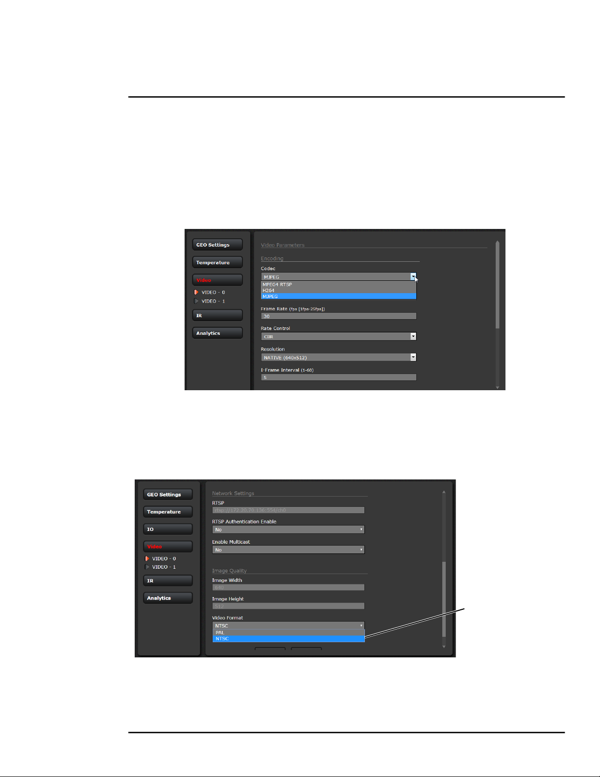
Advanced Configuration
3.1.2 Video Setup
Video: By default, two video streams are enabled for the camera: Video 0 and Video 1. Both video
streams are available for viewing from a client program such as FLIR Latitude, a stand-alone video
player, or a third-party VMS (including ONVIF systems).
By default, Video 0 uses MJPEG encoding and Video 1 uses H.264 encoding. To modify parameters
that affect a particular IP Video stream from the camera, select the appropriate link (for example,
Video - 0).
With the factory configuration, the default parameters provide high-quality full frame-rate video
streams with reasonable bandwidth usage. In general, for most installations it will not be necessary
to modify the default parameters. However in some cases, such as when a video stream is sent over
a wireless network, it may be useful to “tune” the video stream to try to reduce the bandwidth
requirements. In particular, the RTSP Settings, Network Options, and the Settings parameters are
described below.
Select analog
video format
After making adjustments, scroll down to save the changes through power cycles.
427-0089-00-12 Version 160 March 2019 44
Find Quality Products Online at: sales@GlobalTestSupply.com
www.GlobalTestSupply.com
This document does not contain any export-controlled information.

Advanced Configuration
Caution!
Adjustments to these settings should only be made by someone trained with thermal cameras
and a thorough understanding of how the various settings affect the image.
Haphazard changes can lead to image problems including a complete loss of video.
The parameters in the Encoding section will have a
significant impact on the quality and bandwidth
requirements of the video stream. In general it is
recommended that the default values are used initially, and
then individual parameters can be modified and tested
incrementally to determine if the bandwidth and quality
requirements are met.
For the video streams, the Codec options are MPEG4
RTSP, H.264 or MJPEG. MPEG4 RTSP requires the least
amount of processing, and MJPEG requires the most.
The Bit Rate parameter is only used when the Rate Control
parameter is set to CBR (Constant Bit Rate). With the CBR setting, the system attempts to keep the
video at or near the target bit rate.
The I-Frame Interval parameter controls the number of P-frames used between I-frames. I-frames
are full frames of video and the P-frames contain the changes that occurred since the last I-frame. A
smaller I-Frame Interval results in higher bandwidth (more full frames sent) and better video quality.
A higher I-Frame Interval number means fewer I-frames are sent and therefore results in possibly
lower bandwidth and possibly lower quality.
The Resolution parameter controls the video resolution and therefore can have a large impact on
bandwidth usage. The higher the resolution, the larger the size of the frame and the higher the
network bandwidth required. Table 3-3 provides the corresponding resolution for each setting.
Table 3-3: Image Size Settings
Resolution NTSC PAL
NATIVE 640 x 512 640 x 512
D1 720 x 480 720 x 576
VGA 640 x 480 640 x 480
CIF 352 x 240 352 x 288
CIF4 704 x 480 704 x 576
QNATIVE 320 x 256 320 x 256
As a rule of thumb, if the video will be viewed on its own and on a reasonably large screen, a large
image size setting may look better. On the other hand, if the video is shown as a tile in a video wall,
a smaller image size may look as good and consume less bandwidth.
427-0089-00-12 Version 160 March 2019 45
Find Quality Products Online at: sales@GlobalTestSupply.com
www.GlobalTestSupply.com
This document does not contain any export-controlled information.

Advanced Configuration
For enhanced security, RTSP authentication can be
enabled.
By default, the video streams from the camera are sent
using unicast packets rather than multicast. This means a
given packet of IP Video will be sent separately to each
client that has that video stream open. Therefore each
additional client will cause the bandwidth to increase and
cause more overhead on the system in comparison to
multicast.
The Multicast option can be used to limit how much
bandwidth is required for multiple clients, but it requires a
higher level of network administration and an
understanding of how multicast traffic is manged (multicast
addresses, routers and switches, and so on). With
Multicast enabled, new fields are shown, Destination
Network IP address and Destination Port, as well as TTL
(time-to-live). If more than one camera is providing
multicast streams on the network, be sure to configure
each stream with a unique multicast Destination Network
IP address and Destination Port combination.
The time-to-live field controls the ability of IP packets to
traverse network or router boundaries. A value of 1 restricts
the stream to the same subnet. Values greater than 1 allow
ever increasing access between networks.
There are some challenges with streaming video over an IP network, when compared to applications
which are less time-critical, such as email and web browsing. There are requirements which must be
fulfilled to ensure satisfactory video quality in professional security environments. There are many
parameters and factors related to network infrastructure, protocols, codecs, and so on that can affect
the quality and bit rate of a video stream when it is established between the camera and a client.
The video streaming is done using a protocol generally referred to as Real-time Transport Protocol
(RTP), but there are actually many protocols involved, including Real-Time Transport Control
Protocol (RTCP) and Real Time Streaming Protocol (RTSP). In the background, a “negotiation”
takes place to establish a session between the client (such as FLIR Latitude, or a third party VMS or
video player) and the camera. The ports which form a session are negotiated using a protocol such
as RTSP. A client typically requests a video stream using its preferred settings, and the camera can
respond with its preferred settings. As a result, many of the details are established dynamically,
which may run contrary to network security requirements.
In some networks, the RTP/RTSP traffic is carried (tunneled) over Hypertext Transfer Protocol
(HTTP) as that may allow the traffic to cross network boundaries and firewalls. While this method
involves more overhead due to encapsulation, it may be necessary for clients to access the video
streams when HTTP proxies are used.
RTSP is originated and received on even port numbers and the associated RTCP communication
uses the next higher odd port number; the default RTSP Port is 554.
427-0089-00-12 Version 160 March 2019 46
Find Quality Products Online at: sales@GlobalTestSupply.com
www.GlobalTestSupply.com
This document does not contain any export-controlled information.

Advanced Configuration
The default value for the stream from VIDEO - 0 is ch0. For example, the complete connection string
is: rtsp://192.168.250.116/ch0. This stream name can be used to open a video stream with a thirdparty video player. By default the video stream uses the IP address of the camera.
3.1.3 Thermal Image Setup
In most installations it will not be necessary to change the thermal camera from the default settings.
However in some situations, depending on weather, time of day and so on, it may be useful to make
changes to the video image to enhance the image by modifying one or more of the parameters. In
most situations, it will be adequate to select a different Scene Preset (described below). However, be
aware that when the conditions change the camera may need to be adjusted again; for that reason it
is a good idea to know how to restore the factory default settings as well.
IR Page
In the IR page, a single JPEG image (a snapshot) is displayed in the upper right-hand corner. To
update this image at any time, select the Refresh button in the upper right. This will cause the entire
page to refresh, including the image and all the parameter values (be patient, ti may take some
time).
To make adjustments to the thermal image, it is possible to modify the Automatic Gain Control (AGC)
settings, which are grouped under the AGC ROI and AGC headings. The overall image display (also
known as Polarity or Color Palette) is determined by the Look Up Table (LUT) selected in the Misc.
(Lookup Table) section.
427-0089-00-12 Version 160 March 2019 47
Find Quality Products Online at: sales@GlobalTestSupply.com
www.GlobalTestSupply.com
This document does not contain any export-controlled information.

Advanced Configuration
AGC ROI: The AGC Region Of Interest
(ROI) determines what portion of the image
is used in the calculation of the AGC. By
default all of the pixels in the image are
considered (Full Screen); in some cases it
may be possible to improve the contrast if a
portion of the image is excluded. For
example, if the field of view includes a
portion of the sky, typically quite cold, it may
be desirable to restrict the ROI to the portion
of the image below the horizon.
When Custom is selected, a handle is
shown in the center of the screen.
Drag the handle to set
the size of the ROI box.
Drag the ROI box over
the portion of the scene
that will control the AGC.
AGC: The AGC parameters affect how the
overall IR video image appears. The default AGC
algorithm is suitable for most installations, but
further adjustments may provide a more appealing
image, depending on personal preferences. Be
aware that the settings that are optimal at one time
may be less optimal a short time later, since conditions such as weather and time of day affect the
image and are constantly changing.
Experiment with different AGC parameters to find the settings that work best for the particular
installation. Select Save Settings button at the bottom of the page to keep the settings after a power
cycle or select the Factory Defaults button to return the settings to default values.
• Brightness (ITT Mean) setting determines the temperature that is at the middle of the 256
“shades of gray” produced by the AGC. Positive values allow more detail in hotter scenes, while
negative values allow more detail in lower temperature scenes. Range is -4 to 4.
• Contrast (Max Gain) can be used to increase contrast, especially for scenes with little
temperature variation (it may also increase noise due to increased gain). Range is 12 to 24.
• Sharpness (DDE Gain) is used to enhance image details and/or suppress fixed pattern noise.
Positive values increase Sharpness, while negative values soften the image and filter fixed
pattern noise. A setting of 0 is neutral and will not have any effect. Range is -10 to 40.
• AGC Filter determines how quickly a scene will adjust when a hot object appears (or
disappears) within the AGC ROI. If set to a low value, when a hot object enters the ROI, the
AGC will adjust more slowly to the hot object, resulting in a more gradual transition. Range is 1
to 32.
427-0089-00-12 Version 160 March 2019 48
Find Quality Products Online at: sales@GlobalTestSupply.com
www.GlobalTestSupply.com
This document does not contain any export-controlled information.

Advanced Configuration
Misc. (Lookup Table): Each Look Up Table (LUT) provides
a different display of the various detected levels of thermal
energy as either colors or gray-scale values. Look Up Table
1 is white hot and Look Up Table 2 is black hot; the other
tables assign different colors to different temperatures.
These color palettes can also be selected from the Live
Video page (refer to Toggle Palette, pg. 26).
Corridor Mode: Use the Corridor Mode options to set the
orientation of the video when the camera is mounted in a
position other than upright. This setting also changes the
video analytics parameters for FC-Series ID cameras to
match the orientation of the camera mounting.
Save Settings
Click the Save Settings button at the bottom of the page to
store the current settings as power up defaults. To restore
the original settings, select the Factory Defaults button and
then click on Save Settings.
3.1.4 Video Analytics Setup—FC-Series ID only
The Analytics function of the FC-Series ID camera provides the capability to detect motion and
classify detected objects as Human, Vehicle, or Object of Interest based on size and aspect ratio
(height and width).
Note
Objects of interest are detected objects that do not quite match the human or vehicle aspect ratio,
but move through the scene uniformly. For example, a deer, bus, or oversized truck.
Using the Setup menu Analytics page, create motion detection areas, tripwire lines, or masking
areas—up to four of each. Each detection area or tripwire has independent detection properties
(such as detecting a vehicle or human sized object). Use the alarm manager in the Maintenance
menu to define the actions resulting from each alarm condition (Alarm Manager, pg. 62).
Analytics Page
Use this page to set up areas (or regions) or tripwires for analysis. In some situations it may also be
useful to use multiple regions to include (or exclude) different areas in the scene and to set areaspecific detection parameters. The Analytics page allows the user to add four areas and four
427-0089-00-12 Version 160 March 2019 49
Find Quality Products Online at: sales@GlobalTestSupply.com
www.GlobalTestSupply.com
This document does not contain any export-controlled information.

Advanced Configuration
tripwires. Each area/tripwire is assigned an Alarm ID number (1 to 8) based on the order in which
they are created and the available IDs. If an area is deleted, its Alarm Id will be available for reuse.
Calibration
progress
Add Areas
Calibration ToolsGlobal Settings
Figure 3-1: Analytics Page
Analytics Calibration
• The camera must be mounted in its final location in order to calibrate the scene in the field of
view using either the auto or manual calibration tool.
• Analytics must be enabled to calibrate the scene.
• Set detection areas and tripwires.
• After calibration is finished, verify that the analytics detect and classify objects as expected.
Auto Calibration
If the scene is well ordered and without random motion from things such as trees, shrubs, or small
animals, and access is limited to people (the calibration target), then Auto calibration is a good
choice. Auto calibration relearning adjusts the detection size parameters as people (the calibration
target) are detected walking in all areas of the scene. The progress of the auto calibration is shown
as a percent in the top left corner of the image.
Note
It is recommended that cameras mounted sideways to use Corridor Mode should be calibrated
manually. Refer to Corridor Mode, pg. 49.
Step 1 On the camera’s Analytics web page, click the
Calibrate icon.
1
427-0089-00-12 Version 160 March 2019 50
Find Quality Products Online at: sales@GlobalTestSupply.com
www.GlobalTestSupply.com
This document does not contain any export-controlled information.

Advanced Configuration
Step 2 To automatically calibrate detection settings,
2 3
from the Calibration Mode drop-down list,
select Auto.
Step 3 Click Relearn. The camera automatically calibrates the depth of the FoV based on people
walking in the scene. Be sure that people are walking along the entire vertical axis of the
FoV until calibration is finished. The On-Screen Display shows the progress as a
percentage in the upper left corner of the video (see Figure 3-1).
If the calibration takes too long, the scene may require manual calibration.
Step 4 After calibration is complete set up detection areas and check calibration. Refer to Global
Settings, pg. 52, Creating Analytics Regions, pg. 53, and Check Calibration, pg. 54.
Manual Calibration
Step 1 On the camera’s Analytics web page, click the
Calibrate icon.
Step 2 Select Manual for the Calibration mode.
1
Step 3 Set the near size aspect ratio for a person. Have
2
a person walk around at the bottom of the area.
Select the blue box at the bottom of the screen
and drag to fit the subject. Click Save.
4. Far Size
Calibration
3. Near Size
Calibration
Figure 3-2: Manual Calibration
Step 4 Set the far size aspect ratio for a person.
Have a person walk around at the top of the area. Select the blue box at the top of the
screen and drag to fit the subject. Click Save.
Step 5 After calibration is complete set up detection areas and check calibration. Refer to Global
Settings, pg. 52, Creating Analytics Regions, pg. 53, and Check Calibration, pg. 54.
Based on these settings, the analytics calculate a human size that is proportional to the near and far
size calibration over the detection area. The vehicle size is extrapolated from the human size. If a
detected object matches these parameters, a box will be labeled either H for human, V for vehicle, or
O for object of interest.
427-0089-00-12 Version 160 March 2019 51
Find Quality Products Online at: sales@GlobalTestSupply.com
www.GlobalTestSupply.com
This document does not contain any export-controlled information.

Advanced Configuration
Global Settings
Click the settings icon below the image to access
Global Settings.
There are three settings for sensitivity which control the
threshold for detection (as well as false alarms): Low,
Medium, and High. When set to low, the analytics will
detect fewer objects (also fewer false alarms) than when
set to high.
Set Show Regions to Yes to show any detection areas
as black boxes and tripwires as black lines in the video.
The tracking display options are: All Boxes, Classified
Boxes, Show Triggered, and No Boxes. If any of
options to show boxes is selected, a check box enables
a tracking line with each detection box.
• All Boxes—every detected motion is shown with a
box around it
• Classified Boxes—detected motion classified as
vehicle, human, or object of interest is shown with a
box around it labeled “H”, “V”, or “O”.
• Show Triggered—detected motion that triggers an alarm is shown with a box around it.
• No Boxes—detected motion is not shown with a box
• Lines—show the track of an object based on its position from prior frames. This helps to visually
represent speed and direction of motion (only available if All or Classified Boxes is selected).
• Tamper Sensitivity—set the percentage of pixels that are detected as unchanged when
compared to stored history video frames to trigger an alarm.
When done, click Save, and then click the gear icon to return to the Analytics Setup page.
427-0089-00-12 Version 160 March 2019 52
Find Quality Products Online at: sales@GlobalTestSupply.com
www.GlobalTestSupply.com
This document does not contain any export-controlled information.

Advanced Configuration
Creating Analytics Regions
Selected Region
(Alarm Id 3)
Select Direction
Select targets
Manual
Selection
Add Region
Analytics On/Off
Set dependency
Save
To create a detection area, click the add region icon and a new four corner area will appear on the
image. Drag any of the highlighted circles to expand and define the detection area.
To create a more complex area with more than
four corners or a Tripwire, or to mask an area of
the video from motion detection, select the
manual selection icon .
• With Area selected, click in the video to create the first corner of the area. Continue adding
corners (up to 16), then select Finish to complete the area.
• With Tripwire selected, click in the video to create the first point of the line. Continue to the
second point (and more if desired), then select Finish to complete the line.
Note
The direction (left or right) for an alarm over a tripwire line is controlled by both the properties
of each tripwire and the direction in which the line was originally drawn. A direction to the right
is to the right of a person moving from the first point to the second point of the line, etc.
• With Masking Area selected, click in the video to create the first corner of the area. Continue
adding corners, then select Finish to complete the area.
This is motion detection masking; not privacy masking. The video image will still be seen, but
alarms will not be generated. Analytics will be disabled in the masked area. The purpose is to
manually define regions that will not generate motion alarms. For example, this can be helpful to
eliminate alarms from a tree or bush moving in the wind or to perform auto calibration for some
scenes.
Configure the parameters in the Properties box to set the area-specific parameters, including
dependency. Once the parameters are set up properly, scroll down and click the Save button.
427-0089-00-12 Version 160 March 2019 53
Find Quality Products Online at: sales@GlobalTestSupply.com
www.GlobalTestSupply.com
This document does not contain any export-controlled information.

Advanced Configuration
Check Calibration
1. Click the icon and set Analytics Enabled to Yes.
2. Set Show Tracking to Classified Boxes or Show Trig-
gered, then check the Lines box.
3. Click Save.
4. Have subjects (person, car, truck, etc) enter the area or
cross the tripwire at various distances from the camera.
The boxes should be classified correctly and the direction across tripwires should be as expected.
The image below shows a classified human box and tracking
line in a detection region. The boxes are white indicating an
alarm condition has occurred.
2
3
3.2 Maintenance Menu
The following sections describe more advanced camera configuration options that require the admin
login. For the configuration changes in the remainder of this chapter, it is necessary to save the
changes, then stop and restart the server to make the changes effective. Additional configuration
options are available that are not described in this manual. For more information on setting or
changing these camera parameters refer to the Nexus IP Camera Configuration Guide (FLIR Doc
#427-0030-00-28) or contact the local FLIR representative or FLIR Technical Support.
The basic camera configuration settings (LAN Settings, Services, and Security Options) available
through the expert login are described in Server Menu, pg. 28. When logged in as admin, additional
Maintenance menus are accessible, including Sensor, Files and Product Info.
427-0089-00-12 Version 160 March 2019 54
Find Quality Products Online at: sales@GlobalTestSupply.com
www.GlobalTestSupply.com
This document does not contain any export-controlled information.

Advanced Configuration
3.2.1 Sensor Menu
The configuration changes commonly used are done through the Sensor
menu. Described below are configuration steps from the Communications
and Modules selections.
Communications Menu
The primary IP configuration parameters, such as IP address, network
mask, and gateway, are configured with the LAN Settings page (refer to
LAN Settings, pg. 28). The Networking page can be used to configure
some of the other IP networking parameters.
Networking Page: Generally it is assumed the camera network will be
secured through recognized network security measures and best
practices, such as limited physical access, firewalls, and so on. As an
additional security consideration, it is possible to restrict access to the
camera to a limited number of IP Addresses.
It is possible to restrict access to the camera by remote clients by setting the “Allow Anonymous
Clients” to No, and then enter IP addresses for the clients that are allowed access in the Remote
Clients parameter.
The default TCP port for most FLIR IP cameras is 1001. This is the port number that a client program
such as FLIR Latitude can use to communicate with the camera. If using an ONVIF-compliant VMS
as a client, refer to VMS Remote, below.
427-0089-00-12 Version 160 March 2019 55
Find Quality Products Online at: sales@GlobalTestSupply.com
www.GlobalTestSupply.com
This document does not contain any export-controlled information.

Advanced Configuration
If the Enable Network Broadcast Discovery
parameter is set to Yes, the camera sends
out a “discovery” packet on the network
every half second as an Ethernet broadcast.
Enter IP
Addresses
To restrict client programs to allowed IP
addresses, enter allowed IP addresses in
the Remote Clients list, then set the Allow
anonymous clients parameter to No, and
click Save. The changes will not take effect
Set
pulldown
to No
until the server is stopped and started.
After the interface is configured, scroll down and click on the Save button to save the configuration.
The changes will not take effect until the server is stopped and started.
It is also possible to restrict access to the camera from a web browser. Refer to Security Options, pg.
35 to add an allowed IP address to the list in the Restrict Web Configuration section.
File Transfer: The camera can send a captured image when an alarm occurs (as well as storing the
image locally on the camera) if the camera network is configured with an associated FTP or a
Network-attached storage (NAS) server.
Enable
File Transfer
Select Custom
to enter a text
string prefix
Enter the IP address, path, port, user name and password as required by the network. The
FC-Series supports both NAS NFS and NAS Samba. See Alarm Actions, pg. 64.
427-0089-00-12 Version 160 March 2019 56
Find Quality Products Online at: sales@GlobalTestSupply.com
www.GlobalTestSupply.com
This document does not contain any export-controlled information.

Advanced Configuration
VMS Remote: The VMS Remote page provides communication interfaces for devices that connect
to the camera. Authentication when enabled uses the same passwords set from the Server Security
Options page. Refer to Security Options, pg. 35.
For ONVIF,
use the settings
in Interface 1
Scroll down
For Nexus CGI,
use the settings
in Interface 0
Nexus CGI Interface
After the interface is configured, scroll down and click on the Save button to save the configuration.
The changes will not take effect until the server is stopped and started.
ONVIF Interface
The ONVIF (Open Network Video Interface Forum) is an open industry forum for the development of
a global standard for the interface of network video products. An ONVIF-compliant VMS can be used
to control a FLIR camera. Refer to the VMS documentation to determine what parameter values are
needed. By default, the camera is configured with a VMS Remote interface with ONVIF 2.0
parameters (Profile S). After the interface is configured, scroll down and click on the Save button to
save the configuration. The changes will not take effect until the server is stopped and started.
Several types of third-party Video Management Systems (VMS) are supported by FLIR IP cameras.
Because these systems tend to evolve and change over time, contact the local FLIR representative
or FLIR Technical Support to resolve any difficulties or questions about using this feature.
IOI Interface
Install this interface to hand-off FC-Series ID detection events to the PTZ Tracker (trk-101-P). In
order to implement a hand-off from the FC-Series ID camera to a PTZ camera, the FC-Series ID
camera and trk-101-P are bound together from the web interface of the trk-101-P or from the FLIR
Latitude Network Video Management System. Users can define perimeters and areas for the
FC-Series ID camera to monitor (refer to Video Analytics Setup—FC-Series ID only, pg. 49). When a
427-0089-00-12 Version 160 March 2019 57
Find Quality Products Online at: sales@GlobalTestSupply.com
www.GlobalTestSupply.com
This document does not contain any export-controlled information.

Advanced Configuration
moving object is detected by the FC-Series ID, the trk-101-P can control and move the PTZ camera
to autonomously track and zoom in on the motion.
Step 1 Select Maintenance > Sensor > VMS Remote.
Click
Select
Step 2 Click + ( ).
Step 3 From the drop-down list,
select IOI Interface.
Click
Step 4 Click Create.
Step 5 Accept the message “Data for INTERFACE2 saved
correctly”.
Step 6 Using the Start button at the bottom of the page,
Stop and Start the server.
Click Accept at the prompt.
The status will show Server
Stopped.
Click on the Start button again
to restart the server.
Click Accept at the prompt.
The status will show Server
Running.
Link Cameras on trk-101-P Tracker
Link the PTZ camera and the FC-Series ID from the trk-101-P web interface.
Step 1 Ensure that the FC-Series ID Analytics have been calibrated (refer to Analytics
Calibration, pg. 50).
Step 2 With the FC-Series ID Analytics turned off, login to the trk-101-P and set presets for the
bound PTZ camera and link the preset scenes to the FC-Series ID scene.
427-0089-00-12 Version 160 March 2019 58
Find Quality Products Online at: sales@GlobalTestSupply.com
www.GlobalTestSupply.com
This document does not contain any export-controlled information.

Advanced Configuration
This process is outlined here and detailed in the FLIR ioi HTML Edition Units User Guide
which can be downloaded from the ioi Analytics section of the individual product web page
at https://www.flir.com/products/ioi-ptz-tracker/.
Step 3 Ensure that the FC-Series ID detection regions are setup to correspond to the presets on
the trk-101-P (refer to Creating Analytics Regions, pg. 53).
Step 4 Login to the trk-101-P web interface.
Step 5 Select Setup
Step 6 From the Camera > Type & Model screen, verify that the
Camera Model is configured as PTZ.
Step 7 Click Start PTZ Setup.
Step 8 On the Detection and Tracking screen, select Detection
from another camera with Automatic PTZ tracking. Click
Next.
Step 9 Click Calibrate and follow the instructions on the web
interface. Click Next.
Step 10 On the PTZ Synchronization screen, follow the procedure described in the FLIR ioi
HTML Edition Units User Guide. Refer to “Step 3: PTZ Synchronization with Fixed
Cameras” in the section “Using the PTZ Camera Definition Wizard”
Step 11 Set 8 correlation points on the ground for each camera, select Test, and then Link. Refer
to the procedure “To set correlation points in a preset” in the user guide. Click Next and
Finish.
Correlation
Points
Select Fixed
Camera
Set 8 points
on both scenes
Step 12 When finished, return to Live View and click Arm.
427-0089-00-12 Version 160 March 2019 59
Find Quality Products Online at: sales@GlobalTestSupply.com
www.GlobalTestSupply.com
This document does not contain any export-controlled information.

Advanced Configuration
Devices Menu GPIO: On the GPIO page, scroll down to read the current I/O parameters. GPIO is
enabled by default.
Default
Settings
The GPIO must be wired during installation, refer to GPIO Connections, pg. 15. The status of the
GPIO signals are displayed on the Temperature page from the Setup menu, refer to Temperature
Page, pg. 43.
The illustration at the right shows the default
settings for the output signal channel, Input/Output
0.
• The Label setting can be changed to reflect
more specific alarm information which can then
appear in VMS systems such as FLIR Latitude.
• The GPIO Name determines the circuit point for
the GPIO driver and must not be changed. Set
an Initial Value (On or Off) for this output signal.
Output duration
• The Output Reset Interval is used to
automatically reset the output signal after a set
time. Setting the value to 0 prevents the output
from resetting automatically after a timeout. See
also the Alarm Manager GPIO Output State
Mode parameter, GPIO Output from Motion
Alarm, pg. 66.
• Set Alarm Output GPIO Logic to Positive for a normally open switch signal (circuit closes for
alarm), Set GPIO Logic to Negative for a normally closed switch signal (circuit opens for alarm).
427-0089-00-12 Version 160 March 2019 60
Find Quality Products Online at: sales@GlobalTestSupply.com
www.GlobalTestSupply.com
This document does not contain any export-controlled information.

Advanced Configuration
The illustration at the right shows the default settings
for the input signal channel, Input/Output 1.
• The Label setting can be changed to reflect more
specific alarm information which can then appear in
VMS systems such as FLIR Latitude.
• The GPIO Name determines the circuit point for
the GPIO driver and must not be changed.
• Set GPIO Logic to Negative for a normally open switch signal (circuit closes for alarm), Set
GPIO Logic to Positive for a normally closed switch signal (circuit opens for alarm).
Click on the Save button to save any changed settings. The changes will not take effect until the
server is stopped and started.
Input/Output 2 and Input/Output 3 are control signals for the camera heater circuits. The Heater
output signal denotes when the De-Ice button on the Live Video page is activated. The Defog input
signal denotes when the heater can be run at full power. These two signals perform internal
functions and should not be changed.
Refer to the following sections for a description of how to combine the GPIO inputs and outputs with
other alarms. For example, the camera can send the output signal when there is a Video Analytics
alarm. Similarly, the camera can save an image snapshot when there is an input. These associations
are configured with the Alarm Manager module described in Alarm Manager, pg. 62.
Modules Menu
This section describes the On Screen Display (OSD) page, and Alarm Manager page. With the settings on the OSD page, it is possible to display text information (for example, camera name, date/ time, etc.) as an overlay on the video. The OSD text will appear on the IP video streams as well as the analog video output. Use the Alarm Manager page to define rules for camera alarms from Video Analytics or GPIO.
On Screen Display: Use the OSD page to turn on and configure the On Screen Display (OSD)
options. It may be desirable to display text information (such as the name of the camera or the date/
427-0089-00-12 Version 160 March 2019 61
Find Quality Products Online at: sales@GlobalTestSupply.com
www.GlobalTestSupply.com
This document does not contain any export-controlled information.

Advanced Configuration
time) as an overlay on the video image. The OSD configuration page allows selected camera-related
information to be displayed in the analog video and in the IP video streams.
For example, the Label can display the Friendly Name (configured on the Product Info page), the
Hostname (configured on the LAN Settings page) or a Custom text string (using the Text parameter
after selecting Custom).
Each text string can be controlled with the following parameters:
• State (on or off)
• Location (preset location or a Custom X and Y Location)
The OSD text will appear on the IP video streams as well as the analog video output.
Alarm Manager: Use the Alarm Manager page to set the response (action) that results from an individual alarm. It is possible to have more than one action for a single alarm by adding additional rules (for example, one action could capture an image and another could generate an output). If a
427-0089-00-12 Version 160 March 2019 62
Find Quality Products Online at: sales@GlobalTestSupply.com
www.GlobalTestSupply.com
This document does not contain any export-controlled information.

Advanced Configuration
message is to be sent from the camera as a result of an alarm, it is necessary to define Message
Systems and set up Notification Lists (refer to Services Menu, pg. 30).
Set Enable
to Yes
In general, each Alarm Rule describes an alarm Source and a single alarm Action. For the
FC-Series ID camera, the source of the alarm typically will be internal from the video analytics,
although it is also possible for the camera to receive alarms from another camera or device/server
on the network (such as a radar server, input/output server, ground sensor, fence system, or other
security sensor).
Alarm Source: When the source of alarms are internal, for example, from Video Analytics or GPIO
Input, the Alarm Source Server IP Address is set to the localhost value of 127.0.0.1 and the TCP
port is the default 1001. For internal alarms, the FC-Series camera Alarm Source Device ID is set to
0.
The Alarm Source Device Type is chosen from a pull down
menu; not all options are available for a specific camera or
installation.
When the alarm source is Video Analytics the Alarm ID
corresponds to the area or tripwire (1-8), as configured in the
Setup menu. The Alarm ID is set sequentially during the
setup for each alarm source. Refer to Video Analytics
Setup—FC-Series ID only, pg. 49.
When the alarm source is from the GPIO Input the Alarm ID
is changed to the Input ID and is set to 1 (recall the output is IO 0 and the input is IO 1).
427-0089-00-12 Version 160 March 2019 63
Find Quality Products Online at: sales@GlobalTestSupply.com
www.GlobalTestSupply.com
This document does not contain any export-controlled information.
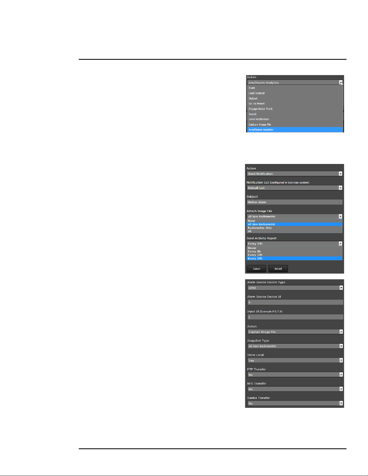
Advanced Configuration
Alarm Actions: Just as there can be multiple
sources of alarms, there are also a variety of
actions or responses to these alarms. Some
actions are only used with pan/tilt cameras.
Actions such as Point, Load ScanList, Go To
Preset, and Engage Radar Track would only be
used with a pan/tilt camera and are not used
with the FC-Series fixed camera.
For the FC-Series ID, typically a rule will be configured to Send a Notification, Capture an Image,
Arm/Disarm Analytics, or generate an Output on the GPIO device. If more than one action is
needed, it is necessary to configure multiple rules. Examples of these actions are provided below.
When the Alarm Action is set to Send Notification, a
Notification List must be selected. The Send Notification
action uses a Msg System and a Notification List that are set
up in the Services menu (refer to Msg Systems, pg. 31).
To attach a snapshot, select the option All Non Radiometric
to send a normal JPEG image from the Attach Image File
pull down list. Radiometric (a special type of JPEG with
temperature data) is not available on the FC-Series ID
camera.
Each rule that sends a notification also has the option to
send an activity report to the same notification list every 6,
12, or 24 hours. The activity report indicates whether or not
an alarm was triggered during the specified time period.
Note that this can be selected on a rule by rule basis.
When the Alarm Action is set to Capture Image File, a
snapshot is stored when the alarm occurs. The image file can
be stored locally in temporary storage (the default), over the
camera network using FTP (file transfer protocol) or to a
network-attached storage device (NAS). Refer to File
Transfer, pg. 56 to configure settings for the FTP, NFS, or
Samba transfers.
The Snapshot type should be set to All Non Radiometric (a
normal JPEG image). Radiometric (a special type of JPEG
with temperature data) is not available on the FC-Series ID
camera.
427-0089-00-12 Version 160 March 2019 64
Find Quality Products Online at: sales@GlobalTestSupply.com
www.GlobalTestSupply.com
This document does not contain any export-controlled information.

Advanced Configuration
Alarm Rule Examples: The following examples show rules that control actions from alarms that
are internal to the camera (rather than coming from another source on the network). The first three
lines and the fifth line of these rules is always the same for the alarms coming from the FC-Series ID
camera itself, and only the source type changes (Video Analytics or GPIO Input).
Enable each alarm rule
Indicates the
alarm comes
from the camera
itself, rather than
another device
on the network.
FC-Series ID Options:
Video Analytics and
GPIO
Video Analytics Alarm to Email: Shown at the right is an
example of an alarm rule that causes an email notification
(with a snapshot image) to be sent when a motion alarm
occurs in Analytics Region 0 or Region 1 (Area or Tripwire).
Refer to Creating Analytics Regions, pg. 53).
The Alarm Source Device Type is set to Video Analytics
with Alarm Id set to “1” corresponding to Analytics Area 1.
The Send Notification action uses a Msg System and a
Notification List that are set up in the Services menu (refer to
Msg Systems, pg. 31). The email includes alarm information,
including the Area ID and if it is a human or vehicle alarm.
When an email is sent, the Alarm Manager can attach a
snapshot from the camera to the email. In Attach Image File,
All Non Radiometric is selected for the type of image.
427-0089-00-12 Version 160 March 2019 65
Find Quality Products Online at: sales@GlobalTestSupply.com
www.GlobalTestSupply.com
This document does not contain any export-controlled information.

Advanced Configuration
GPIO Input to Snapshot: In the example rule shown at the
right the source type of the alarm is GPIO, with the Input ID
set to 1, which corresponds with the input IO 1 (refer to
Devices Menu GPIO, pg. 60), then takes a snapshot and
stores it locally onboard the camera and/or over the camera
network using FTP or an NAS server.
The Action is set to Capture Image File; a snapshot is
stored when the alarm occurs. The image file can be stored
locally in temporary storage (the default), over the camera
network using FTP (file transfer protocol) or to a networkattached storage device (NAS). Refer to File Transfer, pg. 56
to configure settings for the FTP, NFS, or Samba transfers.
GPIO Output from Motion Alarm: The final example
shows an alarm rule that causes a GPIO output when a
motion alarm is detected. The source Alarm Id set to 1
corresponds to Region number 1 on the Analytics Setup
page.
Note: the Associated I/O Port is set to 0, and the Associated
I/O Index is set to 0 (corresponding to Input/Output 0).
The GPIO Output State Mode can be set as Bound or
Unbound. If Bound, the output turns on when an alarm
occurs and turns off when the alarm is cleared or the Output
Reset Interval is reached (see Devices Menu GPIO, pg. 60).
If Unbound, the output turns on when an alarm occurs and
remains on until it is reset by the Output Reset Interval timeout or by a command from the network.
3.2.2 Files Menu
The administrative actions for accessing, updating, and transferring files are
accessed through the Files menu on the left side of the page. Selected actions
from the Firmware, Configuration, and Log pages are described below.
For camera firmware updates, manually install a firmware update file by first
stopping the camera server, browsing to select the update file on your
computer, and then selecting Upload. The firmware files will be uploaded and
installed.
427-0089-00-12 Version 160 March 2019 66
Find Quality Products Online at: sales@GlobalTestSupply.com
www.GlobalTestSupply.com
This document does not contain any export-controlled information.

Advanced Configuration
Caution!
The firmware update procedure resets the FC-Series camera to default settings.
Before performing the update, detach the camera from any VMS.
A firmware update resets video settings, IR settings, and rules to factory defaults.
Analytics are disabled in factory default.
Use the Configuration page to view the Nexus Configuration File, perform Backup & Recovery of
local files (on the camera), and perform Upload & Download of configuration files to another
computer for backup, or to install a new configuration file to the camera.
Shown at the top of the screen is the configuration script file in a scrollable window. This can be
useful if help is ever need help from a support engineer.
In the Backup & Recovery section, click the Restore link associated with the factory.defaults
configuration to restore the camera to its factory settings. This file can not be modified or deleted, so
it is always available.
Use the Backup button to make a backup of the final settings. This will make a backup copy of the
configuration file and store it locally on the camera.
In the Upload & Download section, the Download button can be used to save a copy to a PC for
safe keeping. A pop-up window will ask for a file name and destination folder.
The Upload button is used to transfer a configuration file from a PC to the camera.
427-0089-00-12 Version 160 March 2019 67
Find Quality Products Online at: sales@GlobalTestSupply.com
www.GlobalTestSupply.com
This document does not contain any export-controlled information.

Advanced Configuration
Note
It is also possible to download a camera's configuration files using the following HTTP URL:
http://<ip>/configFilesGet.php, where <ip> is the camera's IP address.
You can manually test the URL or download the files by typing the URL in a web browser.
For security reasons, you cannot download the keys.ini file. The download consists of all other
configuration files.
In the Ethernet Loopback Reset section, selecting No disables the capability to restore the camera’s
Factory Defaults (including its IP address and settings, user passwords, and configuration file) by
temporarily connecting a loopback device to the Ethernet port during initial power-up. The default
setting is Yes. For more information, see Restoring the Factory Settings, pg. 70.
Use the Log page to set logging parameters. Scroll down and select the Download button under
Field Support Log to download a zip file to the computer for field service evaluation.
427-0089-00-12 Version 160 March 2019 68
Find Quality Products Online at: sales@GlobalTestSupply.com
www.GlobalTestSupply.com
This document does not contain any export-controlled information.

Advanced Configuration
Media Browser: The Media Browser page shows all of the images captured by the camera as a
result of an alarm action. The image files can be downloaded to another computer for backup.
Select to preview
Select to Refresh
After selecting a file, the file will appear in the
Preview window.
The file name contains the year, month, day, 24
hour clock time, and the sensor that captured
the image. In this case IR0 is the only sensor.
Select Download to download the selected file
the PC. Select Refresh to check for any
additional images since landing on the Media
Browser page.
Select Edit to select and delete individual
images or all images. Any time the camera is
rebooted or the power removed, the media
directory will be emptied.
Select All
Select Individually
Select all media files by clicking on the Select
All check box. If all files are not selected, the
Select All box will have a minus sign.
The following prompt will appear prior to
deleting any files.
427-0089-00-12 Version 160 March 2019 69
Find Quality Products Online at: sales@GlobalTestSupply.com
www.GlobalTestSupply.com
This document does not contain any export-controlled information.

Advanced Configuration
3.2.3 Product Info Menu
The admin functions accessed through the Product Info menu on the left
side of the page are shown.
The Identification page shows hardware information for the camera and
allows changing the Friendly Name of the camera for easier identification
when multiple cameras are used on the network. You can include the Friendly
Name on the video feeds and adjust its appearance on the OSD page (refer to
On Screen Display, pg. 61).
Click on the Update button to save the settings. The changes will not take
effect until the server is stopped and started.
Enter name
Click Update
3.3 Restoring the Factory Settings
The camera comes configured from the factory with a default IP address (192.168.250.116), the
login passwords (user, expert, admin), and all of the other configuration parameters (stored in a file
called server.ini). In some cases, it may be necessary to restore the network settings of the camera
to the original factory settings. If necessary, the camera IP address can be restored to this factory
default address by temporarily connecting a loopback device to the Ethernet port during initial
power-up (this can be accomplished by using conventional power rather than PoE+). Approximately
30 seconds after power is turned on, the loopback device should be removed to allow the camera to
finish booting up.
Note
The camera will not finish booting up while the loopback device is connected to the camera. The
camera will display analog video, but the Nexus Server will not start until the loopback device is
removed from the camera.
At each power-up, the system transmits a packet and then checks to determine if that same packet
has been received. Detection of the received packet indicates the camera has a custom loopback
connector installed on its Ethernet interface. The detection of the loopback packet cues the camera
to restore Factory Defaults (including the IP settings, user passwords, and configuration file), and to
revert to the same configuration and behavior as when the camera left the factory.
427-0089-00-12 Version 160 March 2019 70
Find Quality Products Online at: sales@GlobalTestSupply.com
www.GlobalTestSupply.com
This document does not contain any export-controlled information.

Advanced Configuration
The custom loopback connector is described below.
Pin # Signal Tied to pin #
1 Transmit + 3
2 Transmit - 6
3 Receive + 1
4 Unused N/A
5 Unused N/A
6 Receive - 2
7 Unused N/A
8 Unused N/A
The RJ45 loopback termination ties pin 1 to pin 3, and pin 2 to pin 6. The other pins are not
connected. This type of device is available commercially (the Smartronix Superlooper Ethernet
Loopback Jack and Plug is one example), or it can be easily made with an RJ45 plug, a couple
wires, and a crimp tool.
After the camera boots up, confirm the startup information is displayed on the analog monitor after
approximately 90 seconds. For example:
S/N: 1234567
IP Addr: 192.168.250.116
427-0089-00-12 Version 160 March 2019 71
Find Quality Products Online at: sales@GlobalTestSupply.com
www.GlobalTestSupply.com
This document does not contain any export-controlled information.

FLIR Systems, Inc.
6769 Hollister Ave
Goleta, CA 93117
USA
Corporate Headquarters
FLIR Systems, Inc.
27700 SW Parkway Ave.
Wilsonville, OR 97070
USA
Support:
https://www.flir. com/support-center/support-hq/
Document:
427-0089-00-12
Version: 160
Date: March 2019
This document does not contain any export-controlled information.
Find Quality Products Online at: sales@GlobalTestSupply.com
www.GlobalTestSupply.com
 Loading...