

User’s manual
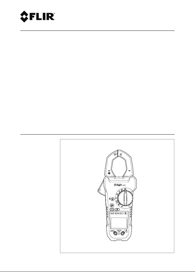
FLIR CM78
True RMS Clamp/DMM with infrared
thermometer and Bluetooth METERLiNK®


User’s manual
FLIR CM78
#T559826; r.9072/9080; en-US


Table of contents
1 Disclaimers. . ... ... . .. . .. . .. . ... ... . .. . .. . ... ... . .. . .. . ... ... ... . .. . .. . .. 1
1.1 Copyright. .. . ... ... ... . .. . ... ... ... . .. . .. . ... ... ... . .. . .. . ... ... 1
1.2 Quality assurance .. ... . .. . .. . ... ... ... . .. . .. . ... ... . .. . .. . ... . 1
1.3 Documentation updates . . .. . .. . ... ... . .. . .. . ... ... . .. . .. . ... .. 1
1.4 Disposal of electronic waste... ... ... . .. . .. . ... ... . .. . .. . ... ... 1
2 Safety information . ... ... ... . .. . .. . ... ... . .. . .. . ... ... ... . .. . .. . ... ... . . 2
2.1 FCC Complicance ... ... . .. . .. . ... ... . .. . .. . ... ... . .. . .. . ... ... 5
2.2 Industry Canada compliance .. . ... ... ... . .. . .. . ... ... ... . .. . .. 6
3 Introduction . . ... ... . .. . .. . ... ... ... . .. . .. . ... ... . .. . .. . ... ... ... . .. . .. . . 7
3.1 Key features. .. . .. . ... ... . .. . .. . ... ... ... . .. . .. . ... ... . .. . .. . ... 7
4 Description . .. . ... ... . .. . .. . ... ... . .. . .. . ... ... ... . .. . .. . ... ... . .. . .. . ... 8
4.1 Meter parts .. . ... ... ... . .. . .. . ... ... . .. . .. . ... ... . .. . .. . ... ... .. 8
4.2 Function switch . .. . ... ... . .. . .. . ... ... ... . .. . .. . ... ... . .. . .. . .. 9
4.3 Function buttons . ... . .. . .. . ... ... ... . .. . .. . ... ... . .. . .. . ... ... 10
4.4 Display icons and indicators .. . ... ... . .. . .. . ... ... ... . .. . .. . .11
5 Operation ... . .. . .. . ... ... . .. . .. . ... ... . .. . .. . ... ... ... . .. . .. . ... ... . .. . .13
5.1 Powering the meter ... ... . .. . .. . ... ... . .. . .. . ... ... ... . .. . .. . .13
5.2 Auto/Manual range . . ... ... . .. . .. . ... ... ... . .. . .. . ... ... . .. . .. 13
5.3 Current measurements . . .. . .. . ... ... ... . .. . .. . ... ... . .. . .. . ..14
5.4 Voltage measurements ... . .. . .. . ... ... . .. . .. . ... ... ... . .. . .. .15
5.5 Resistance measurements . ... ... . .. . .. . ... ... ... . .. . .. . ... ..16
5.6 Capacitance measurements . . ... ... . .. . .. . ... ... . .. . .. . ... ..16
5.7 Frequency measurements .. ... . .. . .. . ... ... . .. . .. . ... ... ... .17
5.8 Type K temperature measurements. ... ... . .. . .. . ... ... . .. . .. 17
5.9 Continuity . . ... ... . .. . .. . ... ... . .. . .. . ... ... ... . .. . ... ... ... . .. 17
5.10 Diode test ... . .. . .. . ... ... . .. . .. . ... ... ... . .. . .. . ... ... . .. . .. . .18
5.11 IR temperature measurements.. . .. . .. . ... ... . .. . .. . ... ... . .. 18
5.12 MAX/MIN mode.. . .. . .. . ... ... ... . .. . .. . ... ... . .. . .. . ... ... ... 20
5.13 Peak hold . . .. . ... ... . .. . .. . ... ... ... . .. . .. . ... ... . .. . .. . ... ... 20
5.14 Temperature units .. . .. . ... ... ... . .. . .. . ... ... . .. . .. . ... ... . .. 21
5.15 Streaming measurement data using Bluetooth . ... ... . .. . .. .21
6 Maintenance. .. . .. . ... ... . .. . .. . ... ... . .. . .. . ... ... ... . .. . .. . ... ... . .. . .23
6.1 Cleaning and storage.. ... . .. . .. . ... ... . .. . .. . ... ... ... . .. . .. .23
6.2 Battery replacement ... ... . .. . .. . ... ... . .. . .. . ... ... ... . .. . .. .23
#T559826; r.9072/9080; en-US v

Table of contents
7 Technical specifications . ... . .. . .. . ... ... ... . .. . .. . ... ... . .. . .. . ... ...24
7.1 General specifications ... . .. . .. . ... ... . .. . .. . ... ... ... . .. . .. . .24
7.2 Electrical range specifications . ... ... . .. . .. . ... ... ... . .. . .. . .25
7.3 Thermal range specifications .. ... ... . .. . .. . ... ... . .. . .. . ... .28
7.4 Maximum input specifications.. . .. . .. . ... ... . .. . .. . ... ... ... .28
8 Technical support ... ... . .. . .. . ... ... . .. . .. . ... ... ... . .. . .. . ... ... . .. . .29
9 Warranties.. . .. . .. . ... ... ... . .. . .. . ... ... . .. . .. . ... ... . .. . .. . .. . ... ... . .30
9.1 FLIR Global Limited Lifetime Warranty . .. . .. . ... ... . .. . .. . ..30
9.2 FLIR Test and Measurement Limited 2 Year
Warranty. . .. . .. . ... ... ... . .. . .. . ... ... . .. . .. . ... ... . .. . .. . ... . 31
#T559826; r.9072/9080; en-US vi

1 Disclaimers
1.1 Copyright
© 2013, FLIR Systems, Inc. All rights reservedworldwide.
No parts of the software including source codemay be reproduced, transmitted, transcribed or translated into any
language or computer language in any form orby any
means, electronic, magnetic, optical, manualor otherwise,
without the prior written permission of FLIR Systems.
The documentation must not, in whole or part, becopied,
photocopied, reproduced, translated or transmitted to any
electronic medium or machine readable form withoutprior
consent, in writing, from FLIR Systems.
Names and marks appearing on the products herein are
either registered trademarks or trademarks of FLIR Systems and/or its subsidiaries. All other trademarks, trade
names or company names referenced herein are usedfor
identification only and are the property oftheir respective
owners.
1.2 Quality assurance
The Quality Management System under which these
products are developed and manufactured hasbeen certified in accordance with the ISO 9001 standard.
FLIR Systems is committed to a policyof continuous development; therefore we reserve the right tomake
changes and improvements on anyof theproducts without prior notice.
1.3 Documentation updates
Our manuals are updated several times per year, and we
also issue product-critical notifications of changes on a
regular basis.
Toaccess thelatest manualsand notifications, go to the
Download tab at:
http://support.flir.com
It only takes a few minutes toregister online. In the download area you will also findthe latestreleases of manuals
for our other products, aswell as manuals for our historical
and obsolete products.
1.4 Disposal of electronic waste
As with most electronic products, this equipment mustbe
disposed of in an environmentally friendly way, and in accordance with existing regulations for electronic waste.
Please contact your FLIR Systems representativefor
more details.
#T559826; r.9072/9080; en-US 1
2 Safety information
Note
Before operating the device, you must read, understand, and follow all instructions, dangers, warnings, cautions, and notes.
Note
FLIR Systems reserves the right to discontinue models, parts or accessories,
and other items, or to change specifications at any time without prior notice.
Note
Remove the batteries if the device is not used for an extended period of time.
WARNING
Do not operate the device if you do not have the correct knowledge. Formal
qualifications and/or national legislation for the electrical inspections can apply. Incorrect operation of the device can cause damage, shock, injury or
death to persons.
WARNING
Do not start the measuring procedure before you have set the function switch
to the correct position. This can cause damage to the instrument and can
cause injury to persons.
WARNING
Do not change to current or resistance when you measure the voltage. This
can cause damage to the instrument and can cause injury to persons.
#T559826; r.9072/9080; en-US 2
2 Safety information
WARNING
Do not measure the current on a circuit when the voltage increases to more
than 600 V. This can cause damage to the instrument and can cause injury to
persons.
WARNING
You must disconnect the test leads from the circuit that you did a test on before you change the range. If you do not do this, damage to the instrument
and injury to persons can occur.
WARNING
Do not look directly into the laser beam. The laser beam can cause eye
irritation.
WARNING
Do not use the laser pointer near explosive gases or in other possible explosive areas. Injury to persons can occur.
WARNING
Do not replace the batteries or the fuses before you remove the test leads.
This can cause damage to the instrument and can cause injury to persons.
WARNING
Do not use the device if the test leads and/or the device show signs of damage. Injury to persons can occur.
#T559826; r.9072/9080; en-US 3
2 Safety information
WARNING
Be careful when you do the measurements if the voltages are more than 25
VAC rms or 35 VDC. There is a risk of shock from these voltages. Injury to persons can occur.
WARNING
Do not do diode, resistance or continuity tests before you have removed the
power from the capacitors and from a device during a test. Injury to persons
can occur.
WARNING
Do not use the device as a tool to identify live terminals. You must use the correct tools. Injury to persons can occur if you do not use the correct tools.
WARNING
Make sure that children cannot touch the device. The device contains dangerous objects and small parts that children can swallow. If a child swallows an
object or a part, speak with a physician immediately. Injury to persons can
occur.
WARNING
Do not let children play with the batteries and/or the packing material. These
can be dangerous for children if they use them as toys.
WARNING
Do not touch expired or damaged batteries without gloves. Injury to persons
can occur.
#T559826; r.9072/9080; en-US 4

2 Safety information
WARNING
Do not cause a short-circuit of the batteries. This can cause damage to the instrument and can cause injury to persons.
WARNING
Do not put the batteries into a fire. Injury to persons can occur.
CAUTION
Do not use the device for a procedure that it is not made for. This can cause
damage to the protection.
This symbol, adjacent to another symbol or terminal, indicates that
the user must refer to the manual for further information.
This symbol, adjacent to a terminal, indicates that, under normal
use, hazardous voltages may be present.
Double insulation.
UL listing is not an indication or a verification of the accuracy of the
meter
2.1 FCC Complicance
This device complies with part 15 of the FCC Rules. Operation is subject to the
following two conditions:
1. This device may not cause harmful interference.
2. This device must accept any interference received, including interference
that may cause undesired operation.
This equipment has been tested and found to comply with the limits for a Class B
digital device, pursuant to part 15 of the FCC Rules. These limits are designed to
provide reasonable protection against harmful interference in a residential installation. This equipment generates, uses, and can radiate radio frequency energy
#T559826; r.9072/9080; en-US 5
2 Safety information
and, if not installed and used in accordance with the instructions, may cause
harmful interference to radio communications. However, there is no guarantee
that interference will not occur in a particular installation. If this equipment does
cause harmful interference to radio or television reception, which can be determined by turning the equipment off and on, the user is encouraged to try to correct the interference by one or more of the following measures:
• Reorient or relocate the receiving antenna.
• Increase the separation between the equipment and receiver.
• Connect the equipment into an outlet on a circuit different from that to which
the receiver is connected.
• Consult the dealer or an experienced radio/TV technician for help.
WARNING
Changes or modifications not expressly approved by the party responsible for
compliance could void the user's authority to operate the equipment.
2.2 Industry Canada compliance
This device complies with Industry Canada licence-exempt RSS standard(s). Operation is subjectto the following two conditions: (1) this device may not cause interference, and (2) this devicemust accept any interference, including
interference that may cause undesired operation of thedevice.
#T559826; r.9072/9080; en-US 6

3 Introduction
Congratulations on your purchase of the FLIR CM78 True RMS Clamp/DMM with
infrared thermometer and Bluetooth METERLiNK®.
This meter is supplied in the METERLiNK® kit and includes a Bluetooth module
designed for use with FLIR infrared cameras. The combination of a clamp meter
and an infrared (IR) camera is used for electrical power measurement, analysis,
and documentation.
The FLIR CM78 measurement functions include AC/DC voltage, AC/DC current,
resistance, capacitance, frequency, diode test, continuity, type k thermocouple
temperature plus non-contact IR temperature.
Proper use and care of this meter will provide many years of reliable service.
3.1 Key features
• True RMS current and voltage measurements.
• Multimeter functions include AC/DC voltage, resistance, capacitance, fre-
quency, diode, and continuity.
• 42 mm (1.7″) jaw opening for conductors up to 400 mm
240 mm
2
(500 MCM).
• 4000–count backlit display.
• Built-in non-contact IR thermometer with laser pointer.
• Features include data hold, minimum/maximum, and auto power off.
• METERLiNK® Bluetooth transmitter wirelessly transmits voltage and current
readings to selected FLIR thermal imaging IR cameras, to incorporate meter
readings with thermal images.
• Complete with CAT IV-1000V Professional Test Leads, 6 x AAA.
• FLIR CM78 METERLiNK® for Android app for remote meter reading.
• Safety Category Rating: CAT IV-600V, CAT III-1000V
2
(750 MCM) or two
#T559826; r.9072/9080; en-US 7

4 Description
4.1 Meter parts
Figure 4.1 Front view
1. Clamp jaw.
2. Jaw opening trigger
3. Function buttons, see section 4.3 Function buttons, page 10.
4. Work light.
5. Function switch, see section 4.2 Function switch, page 9.
6. LCD display.
7. Probe/thermocouple terminals.
#T559826; r.9072/9080; en-US 8

4 Description
Figure 4.2 Rear view
1. IR sensor.
2. Laser pointer diode.
3. Battery compartment.
4.2 Function switch
The meter can measure voltage or frequency through the probe
inputs. The type of measurement is selected by the
button.
The meter can measure resistance, continuity, or diode polarity
through the probe inputs. The type of measurement is selected by
the
button.
The meter can measure capacitance through the probe inputs.
#T559826; r.9072/9080; en-US 9

4 Description
The meter can measure DC current through the clamp jaws.
The meter can measure AC current through the clamp jaws.
The meter can measure temperature through the thermocouple
inputs.
The meter can measure IR temperature through the IR sensor.
The meter is in full power-saving mode
4.3 Function buttons
Press the button to change the operating mode for the currently
selected measurement.
• Use the button to select Auto range or Manual range mode,
see section 5.2 Auto/Manual range, page 13.
• In Manual range mode, press the button to change the range
(scale).
The Peak hold function is available when measuring AC/DC current or voltage.
• Press the button to enter Peak hold mode, see section 5.13
Peak hold, page 20.
• Press the button to toggle between Pmax and Pmin modes.
• Press and hold the button for 2 seconds to return to normal
operation.
• Press the button to enter MAX/MIN mode, see section 5.12
MAX/MIN mode, page 20.
• Press and hold the button for 2 seconds to return to normal
operation.
• Press the button to enable/disable the display backlight.
• Press and hold the button for 2 seconds to enable/disable the
work light.
When the function switch is set to the position, press and hold
the button to capture IR temperature data.
#T559826; r.9072/9080; en-US 10

4 Description
Press the button to toggle between Normal and Hold mode. In
Hold mode, the display freezes the last reading and continues to
display this value.
Press the button to enable/disable METERLiNK® (Bluetooth)
communication, see section .
4.4 Display icons and indicators
Figure 4.3 Display
Indicates that METERLiNK® (Bluetooth) communication is active, see section.
Indicates that the IR sensor and the laser pointer diode are active.
Indicates that the meter is in Auto range mode.
Indicates that the meter is displaying maximum reading values.
Indicates that the meter is displaying minimum reading values.
Indicates that the meter is displaying peak maximum values.
Indicates that the meter is displaying peak minimum values.
Indicates that the meter is displaying values with relative reference applied (solid indicator) or with no reference applied (flashing indicator).
#T559826; r.9072/9080; en-US 11

4 Description
Indicates that the meter is in Hold mode.
Indicates the battery voltage status.
Indicates that the meter is measuring AC current or voltage.
Indicates that the meter is measuring DC current or voltage.
Indicates that the continuity function is active.
Indicates that the diode test function is active.
4.4.1 Out-of-range warning
If the input is out-of-range, OL is displayed on the main display.
#T559826; r.9072/9080; en-US 12

5 Operation
Note
Before operating the device, you must read, understand, and follow all instructions, dangers, warnings, cautions, and notes.
Note
When the meter is not in use, the function switch should be set to the
position.
Note
When connecting the probe leads to the device under test, connect the negative lead before connecting the positive lead. When removing the probe
leads, remove the positive lead before removing the negative lead.
5.1 Powering the meter
1. Set the function switch to any position to switch on the meter.
2. If the battery indicator
does not power on, replace the batteries. See section 6.2 Battery replace-
ment, page 23.
5.1.1 Auto power off
The meter enters sleep mode after 25 minutes of inactivity. To turn on the meter
again, set the function switch to OFF and then set it to any position again. The auto power off time-out is then reset.
shows that the battery voltage is low or if the meter
5.2 Auto/Manual range
In Auto range mode, the meter automatically selects the most appropriate measurement scale. In Manual range mode, the desired range (scale) is set manually.
Auto range is the default method of operation. When any new function is selected
with the function switch, the starting mode is Auto range, and the
displayed.
#T559826; r.9072/9080; en-US 13
indicator is

5 Operation
To enter Manual range mode, press the
press the
button repeatedly until the desired range is displayed.
To return to Auto range mode, press and hold the
button. To change the range,
button until the indi-
cator is displayed.
5.3 Current measurements
When measuring current using the clamp jaws, only one conductor should be enclosed by the jaws—refer to Figure 5.1.
Figure 5.1 Correct and incorrect set-up
1. Ensure that the probe/thermocouple leads are disconnected from the meter.
2. Set the function switch to the
The
or indicator is displayed.
or position.
3. Press the trigger to open the clamp jaws. Fully enclose one conductor—refer
to Figure 5.1. For optimum results, center the conductor in the jaws.
4. Read the current value on the display.
#T559826; r.9072/9080; en-US 14

5 Operation
Note
The meter can also be set to display peak values only, see section 5.13 Peak
hold, page 20.
5.3.1 DC Zero
The DC Zero feature removes offset values and improves the accuracy of DC
current measurements.
1. Set the function switch to the
position.
2. Ensure that there is no conductor in the clamp jaws.
3. Press the
The
4. Use the
button to enter the DC Zero mode and store the offset value.
indicator is displayed.
button to toggle the display between offset applied (solid
indicator) and no offset applied (flashing indicator).
5. To exit the DC Zero mode, press and hold the
tor disappears and the
indicator is displayed.
button. The indica-
5.4 Voltage measurements
1. Set the function switch to the
position.
2. Insert the black probe lead into the negative COM terminal and the red probe
lead into the positive V terminal.
3. Use the
• The
• The
button to select AC or DC voltage measurement.
indicator should be displayed for AC voltage measurements.
indicator should be displayed for DC voltage measurements.
4. Connect the probe leads in parallel to the part under test.
5. Read the voltage value on the display.
Note
The meter can also be set to display peak values only, see section 5.13 Peak
hold, page 20.
#T559826; r.9072/9080; en-US 15

5 Operation
5.5 Resistance measurements
WARNING
Do not do diode, resistance or continuity tests before you have removed the
power from the capacitors and from a device during a test. Injury to persons
can occur.
1. Set the function switch to the
position.
2. Insert the black probe lead into the negative COM terminal and the red probe
lead into the positive Ω terminal.
3. Touch the tips of the probe across the circuit or component under test.
4. Read the resistance value on the display.
5.6 Capacitance measurements
WARNING
Do not do diode, resistance or continuity tests before you have removed the
power from the capacitors and from a device during a test. Injury to persons
can occur.
1. Set the function switch to the
position.
2. Insert the black probe lead into the negative COM terminal and the red probe
lead into the positive
3. Press the
is stored and the
terminal.
button to zero any stray capacitance. The relative reference
indicator is displayed.
4. Touch the tips of the probe across the part under test.
5. Read the capacitance value on the display.
6. Use the
plied (solid
7. To exit the zero (relative) mode, press and hold the
dicator disappears and the
button to toggle the display between relative reference ap-
indicator) and no reference applied (flashing indicator).
button. The in-
indicator is displayed.
#T559826; r.9072/9080; en-US 16

5 Operation
Note
For very large capacitance values, it may take several minutes for the measurement to settle and the final reading to stabilize.
5.7 Frequency measurements
1. Set the function switch to the
position.
2. Insert the black probe lead into the negative COM terminal and the red probe
lead into the positive V terminal.
3. Press and hold the
button to select frequency measurement. The Hz
unit indicator should be displayed.
4. Touch the tips of the probe across the part under test.
5. Read the frequency value on the display.
5.8 Type K temperature measurements
1. Set the function switch to the
position.
2. While observing the correct polarity, insert the thermocouple leads into the
negative COM terminal and the positive
terminal.
3. Touch the tip of the thermocouple to the part under test. Keep the thermocouple tip on the part until the reading on the display stabilizes.
4. Read the temperature value on the display.
5. To avoid electrical shock, disconnect the thermocouple leads before turning
the function switch to another position.
Note
To change the temperature unit, see section 5.14 Temperature units, page 21.
5.9 Continuity
WARNING
Do not do diode, resistance or continuity tests before you have removed the
power from the capacitors and from a device during a test. Injury to persons
can occur.
1. Set the function switch to the
position.
#T559826; r.9072/9080; en-US 17

5 Operation
2. Insert the black probe lead into the negative COM terminal and the red probe
lead into the positive Ω terminal.
3. Use the
button to select continuity measurement. The indicator
should be displayed.
4. Touch the tips of the probe across the circuit or component under test.
5. If the resistance is less than 30 Ω, the meter beeps continuously.
5.10 Diode test
WARNING
Do not do diode, resistance or continuity tests before you have removed the
power from the capacitors and from a device during a test. Injury to persons
can occur.
1. Set the function switch to the
position.
2. Insert the black probe lead into the negative COM terminal and the red probe
lead into the positive Ω terminal.
3. Use the
button to select the diode test function. The indicator
should be displayed.
4. Touch the tips of the probe across the diode or semiconductor junction under
test. Make a note of the value on the display.
5. Reverse the red and black test lead positions to reverse the test polarity.
6. Touch the tips of the probe across the diode or semiconductor junction under
test. Make a note of the new value on the display.
7. The diode or semiconductor junction can be evaluated as follows:
• If one of the readings displays a value (typically 0.400 V or 0.900 V) and
the other reading displays OL, the component is good.
• If both readings display OL, the component is open.
• If both readings are very small or 0, the component is shorted.
5.11 IR temperature measurements
The meter is equipped with a laser pointer diode, which is used as a targeting
pointer for the IR temperature measurements. The target of the measurement
should be larger than the size of the laser beam spot. As the distance from an object increases, the spot size of the area measured by the meter becomes larger.
The meter’s field of view ratio is 8:1, meaning that if the meter is 8 cm (3.2″) from
#T559826; r.9072/9080; en-US 18

5 Operation
the target, the diameter (spot) of the object under test must be at least 1 cm
(0.4″). Refer to Figure 5.2.
Figure 5.2 IR spot-to-distance ratio
IR measurement notes:
• The object under test should be larger than the size of the laser beam spot.
• If the surface of the object under test is covered with frost, oil, grime, etc.,
clean the surface before measuring.
• If the surface of the object is highly reflective, apply masking tape or flat black
paint to the surface before measuring.
• The meter may not make accurate measurements through transparent surfa-
ces such as glass.
• Steam, dust, smoke, etc., may obscure measurements.
• To find a hot spot, aim the meter outside the area of interest, then scan across
(in an up and down motion) until the hot spot is located.
WARNING
Do not look directly into the laser beam. The laser beam can cause eye
irritation.
#T559826; r.9072/9080; en-US 19

5 Operation
WARNING
Do not use the laser pointer near explosive gases or in other possible explosive areas. Injury to persons can occur.
1. Set the function switch to the
2. Press and hold the
position.
button to enable the IR sensor and the laser pointer
diode.
The
indicator is displayed.
3. Aim the laser pointer at the surface to be measured. Read the IR temperature value on the display.
Note
To change the temperature unit, see section 5.14 Temperature units, page 21.
5.12 MAX/MIN mode
The MAX/MIN mode is available for the AC/DC Voltage/Current, Resistance, Capacitance, Type K Temperature, and IR Temperature functions.
1. Press the
button to activate the MAX/MIN recording mode; the will
appear. The meter will display and hold the maximum reading and will update only when a new “max” reading is registered.
2. Press the
button again and the will appear. The meter will now display and hold the minimum reading and will update only when a new “min”
occurs.
3. Press the
button again and two blinking arrows will appear. The
meter will now display the present reading, but will continue to track the
“max” and “min” readings.
4. To exit MAX/MIN mode, press and hold the
button for 2 seconds; the
arrow indicators should switch OFF.
5.13 Peak hold
With the Peak hold function active, the meter captures and displays the positive
and negative peak values and updates only when a higher/lower value is
#T559826; r.9072/9080; en-US 20

5 Operation
registered. The Peak hold function is available when measuring AC/DC current or
voltage.
1. With the meter set to AC/DC current or voltage measurement (see section
5.3 Current measurements, page 14 or 5.4 Voltage measurements, page 15)
press the
2. Press the
button to enter Peak mode.
button toggle between Pmax and Pmin modes.
• In Pmax mode, the
• In Pmin mode, the
indicator is displayed.
indicator is displayed.
3. Read the positive/negative peak value on the display.
4. To return to normal operation, press and hold the
button for 2
seconds.
5.14 Temperature units
The meter displays temperatures in ℃ or ℉. The temperature unit switch is located in the battery compartment.
1. To avoid electrical shock, disconnect the meter if connected to a circuit, remove the probe/thermocouple leads from the terminals, and set the function
switch to the
position before attempting to switch the temperature unit.
2. Unscrew the battery compartment cover and remove the batteries.
3. Set the temperature unit switch to the desired position.
4. Fit the batteries in place and secure the battery compartment cover.
5.15 Streaming measurement data using Bluetooth
5.15.1 General
Some IR cameras from FLIR Systems support Bluetooth communication, and to
those cameras you can stream measurement data from the meter. The data is
then merged into the result table in the IR image.
Streaming measurement data is a convenient way to add important information
to an IR image. For example, when identifying an overheated cable connection,
you may want to know the current in that cable.
The Bluetooth range is 10 m (32 ft.) maximum.
#T559826; r.9072/9080; en-US 21

5 Operation
5.15.2 Procedure
1. Pair the IR camera with the instrument. Refer to the camera manual for information on how to pair Bluetooth devices.
2. Turn on the camera.
3. Turn on the meter.
4. Press the
on the meter to enable Bluetooth.
5. Choose the variable that you want to use (voltage, current, resistance, etc.).
Results from the meter will now automatically be displayed in the result table
in the top left corner of the IR camera screen.
Note
The meter’s internal update rate is faster than that of the Bluetooth data transmission rate; therefore, values displayed on the remote device may differ
slightly from the values displayed on the meter.
#T559826; r.9072/9080; en-US 22

6 Maintenance
6.1 Cleaning and storage
Clean the meter with a damp cloth and mild detergent; do not use abrasives or
solvents.
If the meter is not to be used for an extended period, remove the batteries and
store them separately.
6.2 Battery replacement
1. To avoid electrical shock, disconnect the meter if connected to a circuit, remove the probe/thermocouple leads from the terminals, and set the function
switch to the
2. Unscrew and remove the battery compartment cover.
3. Replace the six standard AAA batteries, observing correct polarity.
4. Secure the battery compartment cover.
6.2.1 Disposal of electronic waste
As with most electronic products, this equipment must be disposed of in an environmentally friendly way, and in accordance with existing regulations for electronic waste.
Please contact your FLIR Systems representative for more details.
position before attempting to replace the batteries.
#T559826; r.9072/9080; en-US 23

7 Technical specifications
7.1 General specifications
Display 4000-count with bar
Controls
Backlight White LED
Work light White LED array
Measurement ranges
Sample rate 20 per second, nominal
Input impedance 10 MΩ (VDC and VAC)
AC voltage bandwidth 45–400 Hz
Power supply 6 × AAA (LR03) batteries
Battery life 100 hours, using alkaline batteries
Auto power off (APO) After 25 minutes (nominal) inactivity;
APO quiescent current
Over-current protection fuse No fuse
Measurement type
Continuity test Visual and audible.Threshold is 30 Ω
• 8-position rotary switch
• Dedicated IR button
• 8 dedicated function buttons:
flashlight, IR, maximum/minimum,
Bluetooth, hold, range, mode,
peak
See section 7.2 Electrical range
specifications, page 25.
reset when the rotary switch is set to
OFF, then set to any position again
50 µA maximum
True RMS, crest factor ≤ 3 at full
scale up to 500 V, decreasing linearly
to ≤ 1.5 at 1000 V
#T559826; r.9072/9080; en-US 24

7 Technical specifications
Other indications Low battery, over-range, IR, memory
Operating temperature –10 to 50℃ (14 to 122℉)
Storage temperature –25 to 60℃ (–14 to 140℉)
Operating humidity Maximum 90% up to 35℃ (95℉) de-
creasing linearly to 60% at 45℃
(113℉)
Storage humidity
90% maximum
Dimensions 257 mm × 110 mm × 50 mm (10.1″ ×
4.3″ × 2.0″)
Weight 0.63 kg (1.4 lb.)
Bluetooth range 10m (32ft) maximum
Safety Category Rating CAT IV-600V, CAT III-1000V
7.2 Electrical range specifications
Valid for ambient temperature conditions 18 to 28 ℃ (64.4 to 82.4 ℉)
Function Range Resolution Accuracy (of
reading)
AC current 400.0 A 0.1 A ±(2.5% + 8
digits)
1000 A 1 A ±(2.8% + 5
digits)
DC current
400.0 A 0.1 A ±(2.5% + 5
digits)
1000 A 1 A ±(2.8% + 5
digits)
#T559826; r.9072/9080; en-US 25

7 Technical specifications
Function Range Resolution Accuracy (of
reading)
AC voltage 400.0 mV 0.1 mV ±(1.5% + 10
digits)
4.000 V 0.001 V ±(1.5% + 5
40.00 V 0.01 V
digits)
400.0 V 0.1 V
1000 V 1 V ±(2.0% + 5
digits)
Note
All AC voltage ranges are specified from 5% of the range to 100% of the
range.
DC voltage 400.0 mV 0.1 mV ±(1.5%+10
digits)
4.000 V 0.001 V ±(1.5% + 2
40.00 V 0.01 V
digits)
400.0 V 0.1 V
1000 V 1 V ±(2.0% + 2
digits)
Resistance
400.0 Ω 0.1 Ω ±(1.0% + 4
digits)
4.000 kΩ 0.001 kΩ ±(1.5% + 2
40.00 kΩ 0.01 kΩ
digits)
400.0 kΩ 0.1 kΩ
4.000 MΩ 0.001 MΩ ±(2.5% + 3
digits)
40.00 MΩ 0.01 MΩ ±(3.5% + 5
digits)
#T559826; r.9072/9080; en-US 26

7 Technical specifications
Function Range Resolution Accuracy (of
reading)
Capacitance 4.000 nF 0.001 nF ±(5.0% + 30
digits)
40.00 nF 0.01 nF ±(5.0% + 20
digits)
400.0 nF 0.1 nF ±(3.0% + 5
4.000 μF 0.001 μF
digits)
40.00 μF 0.01 μF
400.0 μF 0.1 μF ±(4.0% + 10
digits)
4.000 mF 0.001 mF ±(10% + 10
digits)
40.00 mF 0.01 mF Unspecified
Frequency 4.000 kHz 0.001 kHz ±(1.5% + 2
digits)
Sensitivity: 100 V (<50 Hz); 50 V (50–400 Hz); 5 V (401–
4000 Hz)
#T559826; r.9072/9080; en-US 27

7 Technical specifications
7.3 Thermal range specifications
Function Thermocouple
IR range Accuracy (of
range
IR temperature
(8:1 ratio)
–29 to –20℃ (–
20 to –4℉)
–20 to 270℃ (–4
to 518℉)
Type K inputs
(excluding
–20 to 760℃ (–4
to 1400℉)
probe)
7.4 Maximum input specifications
Function Maximum input
AC voltage, DC voltage 1000 V DC/AC
Thermocouple 1000 V DC/AC
Resistance, capacitance, frequency,
1000 V DC/AC
diode test
reading)
±5℃ (±9℉)
±2.0% reading
or ±2℃ (±4℉)
(whichever is
greater)
±(3% rdg + 5℃)
(±(3% rdg + 9℉)
#T559826; r.9072/9080; en-US 28

8 Technical support
Website http://www.flir.com/test
Technical support T&MSupport@flir.com
Repairs Repair@flir.com
#T559826; r.9072/9080; en-US 29

9 Warranties
9.1 FLIR Global Limited Lifetime Warranty
A qualifying FLIR Test and Measurement product (the
“Product”) purchased either directly from FLIR Commercial Systems Inc and affiliates (FLIR) or from anauthorized FLIR distributor or reseller that Purchaser registers
on-line with FLIR is eligible forcoverage under FLIR’s Limited Lifetime Warranty, subject to the terms and conditions
in this document. This warrantyonly applies to purchases
of Qualifying Products (see below) purchased and manufactured after April 1, 2013.
PLEASE READ THIS DOCUMENTCAREFULLY; ITCONTAINS IMPORTANT INFORMATION ABOUT THE PRODUCTS THAT QUALIFY FOR COVERAGEUNDER THE
LIMITED LIFETIME WARRANTY, PURCHASER’S OBLIGATIONS, HOWTO ACTIVATE THE WARRANTY, WARRANTY COVERAGE, AND OTHER IMPORTANTTERMS,
CONDITIONS, EXCLUSIONS AND DISCLAIMERS.
1. PRODUCT REGISTRATION. To qualify forFLIR’s Limited Lifetime Warranty, Purchaser must fully register the
Product directly with FLIR on-line at http://www.flir.com
within Sixty (60) DAYS of the date the Product waspurchased by the first retail customer (the “PurchaseDate”).
Qualifying PRODUCTS THAT ARE NOTREGISTERED
ON-LINE WITHIN SIXTY (60) DAYS OF THE PURCHASE
DATE WILL HAVE A LIMITED ONE YEARWARRANTY
FROM DATE OF PURCHASE.
2. QUALIFYING PRODUCTS. Uponregistration, Test and
Measurement products that qualify for coverage under
FLIR’s Limited Lifetime Warranty are: MR7x, CM7x,
CM8x, DMxx, VP5x not including accessories which may
have their own warranty.
3. WARRANTY PERIODS. Forpurposes of the The Limited Lifetime Warranty, Lifetime is defined as seven years
(7) after the product is no longer manufactured,or ten
years (10) from date of purchase, whichever is greater.
This Warranty is only applicableto the original owner of
the Products.
Any Product that is repaired or replaced under warranty is
covered under this Limited Lifetime Warranty for one hundred eighty days (180) daysfrom the date of return shipment by FLIR or for the remaining durationof the
applicable Warranty Period, whichever is longer.
4. LIMITED WARRANTY. In accordance with theterms
and conditions of this Limited Lifetime Warranty, and except as excluded or disclaimed inthis document, FLIR
warrants, from the Purchase Date, thatall fully registered
Products will conform to FLIR’spublished Product specifications and be free from defects in materialsand workmanship during the applicable Warranty Period.
PURCHASER’S SOLE AND EXCLUSIVE REMEDY
UNDER THIS WARRANTY, AT FLIR’S SOLE DISCRETION, IS THE REPAIR OR REPLACEMENT OF
DEFECTIVE PRODUCTS IN A MANNER, AND BY A
SERVICE CENTER, AUTHORIZED BY FLIR. IF THIS
REMEDY IS ADJUDICATED TO BE INSUFFICIENT, FLIR
SHALL REFUND PURCHASER’S PAID PURCHASE
PRICE AND HAVE NOOTHER OBLIGATION OR LIABILITY TO BUYER WHATSOEVER.
5. WARRANTY EXCLUSIONSAND DISCLAIMERS.
FLIR MAKES NO OTHER WARRANTY OF ANYKIND
WITH RESPECT TO THE PRODUCTS. ALL OTHER
WARRANTIES, EXPRESS OR IMPLIED, INCLUDING
BUT NOT LIMITED TO IMPLIED WARRANTIES OF MERCHANTABILITY, FITNESS FOR A PARTICULAR PURPOSE (EVEN IF PURCHASER HAS NOTIFIEDFLIR OF
ITS INTENDED USE FOR THE PRODUCTS),AND NONINFRINGEMENT ARE EXPRESSLY EXCLUDEDFROM
THIS AGREEMENT.
THIS WARRANTY EXPRESSLY EXCLUDES ROUTINE
PRODUCT MAINTENANCE, SOFTWARE UPDATES,
AND REPLACEMENT OF MANUALS, FUSES, OR DISPOSABLE BATTERIES.FLIR FURTHER EXPRESSLY
DISCLAIMS ANY WARRANTYCOVERAGE WHERE
THE ALLEGED NONCONFORMITY IS DUE TO NORMAL WEAR ANDTEAR, OTHER ALTERATION, MODIFICATION, REPAIR, ATTEMPTEDREPAIR, IMPROPER
USE, IMPROPER MAINTENANCE, NEGLECT, ABUSE,
IMPROPER STORAGE, FAILURE TO FOLLOWANY
PRODUCT INSTRUCTIONS, DAMAGE (WHETHER
CAUSED BYACCIDENT OR OTHERWISE), OR ANY
OTHER IMPROPER CARE OR HANDING OFTHE
PRODUCTS CAUSED BYANYONE OTHER THANFLIR
OR FLIR’S EXPRESSLY AUTHORIZED DESIGNEE.
THIS DOCUMENT CONTAINS THE ENTIRE WARRANTY AGREEMENT BETWEEN PURCHASER AND
FLIR AND SUPERSEDES ALL PRIOR WARRANTY NEGOTIATIONS,AGREEMENTS, PROMISES AND
UNDERSTANDINGS BETWEENPURCHASER AND
FLIR. THIS WARRANTY MAY NOT BE ALTERED WITHOUT THE EXPRESS WRITTEN CONSENT OFFLIR.
6. WARRANTY RETURN, REPAIR AND REPLACEMENT. To be eligible for warrantyrepair or replacement,
Purchaser must notify FLIR within thirty (30) days of discovering of any apparent defectin materials or workmanship. Before Purchaser may returna Product for warranty
service or repair, Purchaser must first obtain areturned
material authorization (RMA) number from FLIR. To obtain
the RMA number Owner must provide an originalproof of
purchase. For additional information, to notify FLIRof an
apparent defect in materials or workmanship, or to request
an RMA number, visit http://www.flir.com. Purchaser is
solely responsible for complying with all RMA instructions
provided by FLIR including but not limited toadequately
packaging the Product for shipment to FLIR andfor all
packaging and shipping costs. FLIR will payfor returning
to Purchaser any Product that FLIR repairs orreplaces
under warranty.
#T559826; r.9072/9080; en-US 30

9 Warranties
FLIR reserves the right to determine, in itssole discretion,
whether a returned Product is covered underWarranty. If
FLIR determines that any returned Product isnot covered
under Warranty or is otherwise excluded from Warranty
coverage, FLIR may chargePurchaser areasonable handling fee and return the Product to Purchaser, at Purchaser’s expense, or offerPurchaser theoption of handling the
Product as a non-warranty return.
7. NON-WARRANTY RETURN. Purchaser mayrequest
that FLIR evaluate andserv iceor repair a Product not covered under warranty, which FLIR may agree to do in its
sole discretion. Before Purchaser returns a Product for
non-warranty evaluation and repair, Purchaser must contact FLIR by visiting http://www.flir.com to request an evaluation and obtain an RMA. Purchaser is solely
responsible for complying with all RMA instructions provided by FLIR including but not limited toadequately
packaging the Product for shipment to FLIRand forall
packaging and shipping costs. Upon receipt ofan authorized non-warranty return, FLIR will evaluate the Product
and contact Purchaser regarding the feasibility ofand the
costs and fees associated with Purchaser’s request. Purchaser shall be responsible for the reasonable cost of
FLIR’s evaluation, forthe costof any repairs or services
authorized by Purchaser, andfor thecost of repackaging
and returning the Product to Purchaser.
Any non-warranty repair of a Productis warranted for one
hundred eighty days (180) daysfrom the date of return
shipment by FLIR to be free from defectsin materials and
workmanship only,subject to all of the limitations, exclusions and disclaimers in this document.
9.2 FLIR Test and Measurement Limited 2 Year Warranty
A qualifying FLIR Test and Measurement product (the
“Product”) purchased either directly from FLIR Commercial Systems Inc and affiliates (FLIR) or from anauthorized FLIR distributor or reseller that Purchaser registers
on-line with FLIR is eligible forcoverage under FLIR’s Limited Warranty, subject to the terms and conditions in this
document. This warranty onlyapplies to purchases of
Qualifying Products (see below) purchased and manufactured after April 1, 2013.
PLEASE READ THIS DOCUMENTCAREFULLY; ITCONTAINS IMPORTANT INFORMATION ABOUT THE PRODUCTS THAT QUALIFY FOR COVERAGEUNDER THE
LIMITED WARRANTY, PURCHASER’S OBLIGATIONS,
HOW TO ACTIVATE THEWARRANTY, WARRANTY
COVERAGE, AND OTHERIMPORTANT TERMS, CONDITIONS, EXCLUSIONS AND DISCLAIMERS.
1. PRODUCT REGISTRATION. To qualify forFLIR’s Limited Warranty, Purchaser must fully register the Product directly with FLIR on-line at http://www.flir.com within Sixty
(60) DAYS of the date the Product was purchased bythe
first retail customer (the “Purchase Date”). Qualifying
PRODUCTS THAT ARE NOTREGISTERED ON-LINE
WITHIN SIXTY (60) DAYS OF THE PURCHASE DATE
WILL HAVE A LIMITEDONE YEARWARRANTY FROM
DATEOF PURCHASE.
2. QUALIFYING PRODUCTS. Upon registration,Test and
Measurement products that qualify for coverage under
FLIR’s Limited Warrantyare: VS70 Videoscope, VSAxx
Articulation Camera, VSCxx Camera, VSSxx Probe Spool,
VST handset, MR02 Pin Extension Probe,and TAxx not
including accessories which may havetheir ownwarranty.
3. WARRANTY PERIODS. The applicableLimited Warranty Period measured from the Purchase dataare:
Products Limited Warranty
VS70, VSAxx, VSCxx,
VSSxx, VST, MR02,
TAxx
Any Product that is repaired or replaced under warrantyis
covered under this Limited Warranty forone hundred
eighty days (180) days fromthe date of return shipment
by FLIR or for the remaining duration ofthe applicable
Warranty Period, whichever is longer.
4. LIMITED WARRANTY. In accordance with the terms
and conditions of this Limited Warranty, and except as excluded or disclaimed in this document, FLIR warrants,
from the Purchase Date, that all fully registeredProducts
will conform to FLIR’s published productspecifications
and be free from defects in materials and workmanship
during the applicable Warranty Period.PURCHASER’S
SOLE AND EXCLUSIVE REMEDY UNDER THIS WARRANTY, AT FLIR’S SOLE DISCRETION, ISTHE REPAIR
OR REPLACEMENT OF DEFECTIVEPRODUCTS IN A
MANNER, AND BYA SERVICE CENTER, AUTHORIZED
BY FLIR. IF THIS REMEDY IS ADJUDICATEDTO BE INSUFFICIENT, FLIRSHALL REFUND PURCHASER’S
PAID PURCHASEPRICE ANDHAVE NO OTHER OBLIGATION OR LIABILITYTO BUYER WHATSOEVER.
5. WARRANTY EXCLUSIONSAND DISCLAIMERS.
FLIR MAKES NO OTHER WARRANTY OF ANYKIND
WITH RESPECT TO THE PRODUCTS. ALL OTHER
WARRANTIES, EXPRESS OR IMPLIED, INCLUDING
BUT NOT LIMITED TO IMPLIED WARRANTIES OF MERCHANTABILITY, FITNESS FOR A PARTICULAR PURPOSE (EVEN IF PURCHASER HAS NOTIFIEDFLIR OF
ITS INTENDED USE FOR THE PRODUCTS),AND NONINFRINGEMENT ARE EXPRESSLY EXCLUDEDFROM
THIS AGREEMENT.
THIS WARRANTY EXPRESSLY EXCLUDES ROUTINE
PRODUCT MAINTENANCE, SOFTWARE UPDATES,
AND REPLACEMENT OF FUSES,OR DISPOSABLE
BATTERIES.FLIR FURTHER EXPRESSLY DISCLAIMS
ANY WARRANTYCOVERAGE WHERE THE ALLEGED
NONCONFORMITY IS DUE TO NORMALWEAR AND
TEAR, OTHER ALTERATION, MODIFICATION, REPAIR,
ATTEMPTED REPAIR, IMPROPER USE, IMPROPER
Period
TWO (2) Years
#T559826; r.9072/9080; en-US 31

9 Warranties
MAINTENANCE, NEGLECT, ABUSE, IMPROPER STORAGE, FAILURETO FOLLOW ANY PRODUCT INSTRUCTIONS, DAMAGE (WHETHER CAUSED BY ACCIDENT
OR OTHERWISE), OR ANYOTHER IMPROPER CARE
OR HANDING OF THE PRODUCTS CAUSED BY ANYONE OTHER THAN FLIR ORFLIR’S EXPRESSLYAUTHORIZED DESIGNEE.
THIS DOCUMENT CONTAINS THE ENTIRE WARRANTY AGREEMENT BETWEEN PURCHASER AND
FLIR AND SUPERSEDES ALL PRIOR WARRANTY NEGOTIATIONS,AGREEMENTS, PROMISES AND
UNDERSTANDINGSBETWEEN PURCHASERAND
FLIR. THIS WARRANTY MAY NOT BE ALTERED WITHOUT THE EXPRESS WRITTEN CONSENTOF FLIR.
6. WARRANTY RETURN, REPAIR AND REPLACEMENT.To be eligible for warranty repair or replacement,
Purchaser must notify FLIR within thirty (30) days of discovering of any apparent defectin materials or workmanship. Before Purchaser may returna Product for warranty
service or repair, Purchaser must first obtaina returned
material authorization (RMA) number from FLIR. To obtain
the RMA number Owner must provide an originalproof of
purchase. For additional information, to notifyFLIR of an
apparent defect in materials or workmanship, or to request
an RMA number, visit http://www.flir.com. Purchaser is
solely responsible for complying with all RMA instructions
provided by FLIR including but not limitedto adequately
packaging the Product for shipment to FLIRand forall
packaging and shipping costs. FLIR will payfor returning
to Purchaser any Product that FLIR repairs orreplaces
under warranty.
FLIR reserves the right to determine, in its solediscretion,
whether a returned Product is covered under Warranty. If
FLIR determines that any returned Product isnot covered
under Warranty or is otherwise excluded from Warranty
coverage, FLIR may charge Purchasera reasonablehandling fee and return the Product to Purchaser, at Purchaser’s expense, or offerPurchaser theoption of handling the
Product as a non-warranty return.
7. NON-WARRANTY RETURN. Purchaser mayrequest
that FLIR evaluate and serviceor repair a Product not covered under warranty,which FLIR may agree to do in its
sole discretion. Before Purchaser returns a Product for
non-warranty evaluation and repair, Purchaser must contact FLIR by visiting http://www.flir.com to request an evaluation and obtain an RMA. Purchaser is solely
responsible for complying with all RMA instructions provided by FLIR including but not limited to adequately
packaging the Product for shipment to FLIR andfor all
packaging and shipping costs. Upon receipt ofan authorized non-warranty return, FLIR will evaluate the Product
and contact Purchaser regarding the feasibility ofand the
costs and fees associated with Purchaser’srequest. Purchaser shall be responsible for the reasonable cost of
FLIR’s evaluation, for thecost of any repairs or services
authorized by Purchaser, and forthe cost of repackaging
and returning the Product to Purchaser.
Any non-warranty repair of a Productis warranted for one
hundred eighty days (180) days from the date of return
shipment by FLIR to be free from defectsin materials and
workmanship only,subject to all of the limitations, exclusions and disclaimers in this document.
#T559826; r.9072/9080; en-US 32


A note on the technical production of this publication
This publication was produced using XML — the eXtensible Markup Language.
For more information about XML, please visit http://www.w3.org/XML/
A note on the typeface used in this publication
This publication was typeset using Linotype Helvetica™ World. Helvetica™ was
designed by Max Miedinger (1910–1980)
LOEF (List Of Effective Files)
T501021.xml; en-US; 9072; 2013-09-20
T505544.xml; en-US; 9030; 2013-09-18
#T559826; r.9072/9080; en-US 34


Corporate Headquarters
last page
FLIR Systems, Inc.
27700 SW Parkway Ave.
Wilsonville, OR 97070
USA
Telephone: +1-503-498-3547
Website
http://www.flir.com
Customer support
http://support.flir.com
Publ. No.: T559826
Commit: 9072
Head: 9080
Language: en-US
Modified: 2013-09-20
Formatted: 2013-09-23
 Loading...