


User’s manual
FLIR Exx series
Find Quality Products Online at: sales@GlobalTestSupply.com
www.GlobalTestSupply.com

Important note
Before operating the device, you must read, understand, and follow all instructions, warnings, cautions, and legal disclaimers.
Důležitá poznámka
Před použitím zařízení si přečtěte veškeré pokyny, upozornění, varování a vyvázání se ze záruky, ujistěte se, že jim rozumíte, a řiďte
se jimi.
Vigtig meddelelse
Før du betjener enheden, skal du du læse, forstå og følge alle anvisninger, advarsler, sikkerhedsforanstaltninger og
ansvarsfraskrivelser.
Wichtiger Hinweis
Bevor Sie das Gerät in Betrieb nehmen, lesen, verstehen und befolgen Sie unbedingt alle Anweisungen, Warnungen,
Vorsichtshinweise und Haftungsausschlüsse
Σημαντική σημείωση
Πριν από τη λειτουργία της συσκευής, πρέπει να διαβάσετε, να κατανοήσετε και να ακολουθήσετε όλες τις οδηγίες,
προειδοποιήσεις, προφυλάξεις και νομικές αποποιήσεις.
Nota importante
Antes de usar el dispositivo, debe leer, comprender y seguir toda la información sobre instrucciones, advertencias, precauciones y
renuncias de responsabilidad.
Tärkeä huomautus
Ennen laitteen käyttämistä on luettava ja ymmärrettävä kaikki ohjeet, vakavat varoitukset, varoitukset ja lakitiedotteet sekä
noudatettava niitä.
Remarque importante
Avant d'utiliser l'appareil, vous devez lire, comprendre et suivre l'ensemble des instructions, avertissements, mises en garde et
clauses légales de non-responsabilité.
Fontos megjegyzés
Az eszköz használata előtt figyelmesen olvassa el és tartsa be az összes utasítást, figyelmeztetést, óvintézkedést és jogi
nyilatkozatot.
Nota importante
Prima di utilizzare il dispositivo, è importante leggere, capire e seguire tutte le istruzioni, avvertenze, precauzioni ed esclusioni di
responsabilità legali.
重要な注意
デバイスをご使用になる前に、あらゆる指示、警告、注意事項、および免責条項をお読み頂き、その内容を理解して従ってくだ
さい。
중요한 참고 사항
장치를 작동하기 전에 반드시 다음의 사용 설명서와 경고, 주의사항, 법적 책임제한을 읽고 이해하며 따라야 합니다.
Viktig
Før du bruker enheten, må du lese, forstå og følge instruksjoner, advarsler og informasjon om ansvarsfraskrivelse.
Belangrijke opmerking
Zorg ervoor dat u, voordat u het apparaat gaat gebruiken, alle instructies, waarschuwingen en juridische informatie hebt
doorgelezen en begrepen, en dat u deze opvolgt en in acht neemt.
Ważna uwaga
Przed rozpoczęciem korzystania z urządzenia należy koniecznie zapoznać się z wszystkimi instrukcjami, ostrzeżeniami,
przestrogami i uwagami prawnymi. Należy zawsze postępować zgodnie z zaleceniami tam zawartymi.
Nota importante
Antes de utilizar o dispositivo, deverá proceder à leitura e compreensão de todos os avisos, precauções, instruções e isenções de
responsabilidade legal e assegurar-se do seu cumprimento.
Важное примечание
До того, как пользоваться устройством, вам необходимо прочитать и понять все предупреждения, предостережения и
юридические ограничения ответственности и следовать им.
Viktig information
Innan du använder enheten måste du läsa, förstå och följa alla anvisningar, varningar, försiktighetsåtgärder och
ansvarsfriskrivningar.
Önemli not
Cihazı çalıştırmadan önce tüm talimatları, uyarıları, ikazları ve yasal açıklamaları okumalı, anlamalı ve bunlara uymalısınız.
重要注意事项
在操作设备之前,您必须阅读、理解并遵循所有说明、警告、注意事项和法律免责声明。
重要注意事項
操作裝置之前,您務必閱讀、了解並遵循所有說明、警告、注意事項與法律免責聲明。
Find Quality Products Online at: sales@GlobalTestSupply.com
www.GlobalTestSupply.com

Table of contents
1 Disclaimers ......................................................................................1
1.1 Legal disclaimer ............................ ................................ ..... ...... 1
1.2 U.S. Government Regulations.. ..... ..... ...................... ..... ..... .......... 1
1.3 Patents.... ..... ........................... ..... ........................... ..... .......... 1
1.4 Quality assurance . ..... ..... ..... ........................... ..... ..................... 1
1.5 Third-party licenses.......................... ..... ..... ........................... .... 1
1.6 Usage statistics .......... ..... ................................ ..... ..... ..... .......... 1
1.7 Copyright .......................... ..... ........................... ..... .................1
2 Safety information .............................................................................2
3 Notice to user ................................................................................... 6
3.1 Online documentation . ..... ..... ................. ..... ..... ..... ..................... 6
3.2 Register your camera... ..... ...................... ..... ..... ......................... 6
3.3 Accuracy ........ ..... ..... ..... ................................ ......................... 6
3.4 Calibration....... ..... ........................... ..... ........................... ..... ... 6
3.5 Training ... ..... ..... ..... ................. ..... ..... ..... ................................ 6
3.6 Important note about this manual... ..... ........................... ..... .......... 6
3.7 Note about authoritative versions.. ..... ................................ ..... ...... 7
3.8 Disposal of electronic waste ......... ..... ..... ..... ................. ..... ..... ..... 7
4 Customer help ..................................................................................8
4.1 General .... ................. ..... ..... ..... ........................... ..... ..............8
4.2 Submitting a question .................... ..... ........................... ..... .......8
4.3 Downloads ............................ ................................ .................. 8
5 Quick start guide ...............................................................................9
5.1 To keep in mind .............. ..... ..... ..... ................. ..... ..... ..... ..... ...... 9
6 Camera overview............................................................................. 11
6.1 View from the front ......................... ................................ ..... .... 11
6.2 View from the rear ..... ........................... ..... .............................. 13
6.3 Laser distance meter and laser pointer ............................... ..... .... 14
6.3.1 Laser transmitter and receiver ... ..... ..... ..... ...................... . 15
6.3.2 Difference in position ..................... ..... .......................... 15
6.3.3 Laser warning label... ..... ..... ..... ................. ..... ..... ..... ..... 16
6.3.4 Laser rules and regulations .... ..... ..... ........................... ... 17
6.4 Screen elements ........................... ................................ ..... .... 17
6.4.1 General......................... ..... ........................... ..... ........ 17
6.4.2 Menu system.................. ..... ..... ..... ................. ..... ..... ... 17
6.4.3 Status icons and indicators.... ................................ ..... .... 18
6.4.4 Swipe-down menu....... ..... ........................... ..... ............ 18
6.4.5 Image overlay information .... ..... ........................... ..... ..... 19
6.5 Navigating the menu system................... ..... .............................. 20
6.5.1 Navigating using the navigation pad .... ................. ..... ..... .. 20
7 Handling the camera ........................................................................ 22
7.1 Charging the battery............ ..... ........................... ..... ............... 22
7.1.1 General......................... ..... ........................... ..... ........ 22
7.1.2 Using the stand-alone battery charger to charge the
7.1.3 Using the USB battery charger to charge the battery ............ 22
7.1.4 Charging the battery using a USB cable connected to a
7.2 Removing the battery.... ..... ..... ..... ........................... ..... ............ 25
7.3 Turning on and turning off the camera.. ........................... ..... ........ 26
7.4 Adjusting the thermal camera focus ..... ..... ..... ............ ..... ..... ..... .. 26
7.4.1 Manual focus.................. ..... ........................... ..... ........ 26
7.4.2 Autofocus ..... ................. ..... ..... ..... .............................. 27
7.4.3 Continuous autofocus ................ ..... .............................. 29
battery .. ........................... ..... ........................... ..... ..... 22
computer....................... ..... ........................... ..... ..... ... 24
Find Quality Products Online at: sales@GlobalTestSupply.com
www.GlobalTestSupply.com

Table of contents
7.5 Operating the laser distance meter ..... ........................... ..... ..... ... 29
7.5.1 General......................... ..... ........................... ..... ........ 29
7.5.2 Procedure ......................... ..... ..... ...................... ..... .... 30
7.6 Measuring areas .......... ..... ........................... ..... ...................... 31
7.6.1 General......................... ..... ........................... ..... ........ 31
7.6.2 Procedure ......................... ..... ..... ...................... ..... .... 32
7.7 Connecting external devices and storage media . ..... ..... ..... ............ 32
7.8 Moving files to a computer . ..... ..... ..... ........................... ..... ........ 33
7.8.1 Related topics ............. ................................ ..... ..... ..... . 35
7.9 Programmable button .................... ..... ..... ..... ..... ............ ..... ..... 36
7.9.1 Programmable button options .. ..... ..... ................. ..... ..... .. 36
7.10 Using the camera lamp as a flash ......... ..... ..... ..... ....................... 37
7.11 Hand strap ... ................................ ..... ..... ..... ................. ..... .... 38
7.11.1 Mounting the hand strap ........................ ..... ................... 40
7.12 Lanyard strap................. ..... ........................... ..... ................... 43
7.13 Wrist strap............................. ..... ..... ..... ................. ..... ..... ..... . 44
7.14 Front protection .......... ..... ................................ ....................... 47
7.15 Changing camera lenses ................. ..... ..... ...................... ..... .... 48
7.16 Calibrating the lens–camera combination .................... ..... ............ 53
7.16.1 Introduction... ................. ..... ..... ..... ........................... ... 53
7.16.2 AutoCal procedure ......... ..... ................................ ..... .... 54
7.17 Calibrating the compass .... ..... ..... ..... ................. ..... ..... ..... ........ 57
8 Saving and working with images ....................................................... 58
8.1 About image files ........ ..... ..... ..... ...................... ..... ..... ..... ........ 58
8.1.1 General......................... ..... ........................... ..... ........ 58
8.1.2 File-naming convention .... ..... ..... ..... ................. ..... ..... ... 58
8.1.3 Storage capacity .................... ..... ........................... ..... . 58
8.1.4 About UltraMax...................... ..... ..... ..... ................. ..... . 58
8.2 Saving an image ............. ..... ........................... ..... ..... ..... ..... .... 59
8.3 Previewing an image .................. ..... ..... ..... ................. ..... ..... ... 59
8.4 Opening a saved image..... ................................ ....................... 60
8.5 Editing a saved image.............. ..... ..... ..... ........................... ..... . 60
8.5.1 Related topics ............. ................................ ..... ..... ..... . 61
8.6 Displaying the image information ..... ..... ..... ................. ..... ..... ..... . 61
8.7 Zooming an image ................................ ..... ........................... .. 61
8.8 Deleting images ................. ..... ..... ..... ........................... ..... ..... 61
8.9 Resetting the image counter............ ..... ........................... ..... ..... 62
9 Cloud connectivity........................................................................... 63
9.1 Uploading to FLIR Ignite .............. ..... ..... ..... ................. ..... ..... ... 63
9.2 Connecting to internet .......... ..... ........................... ..... ............... 63
9.2.1 Connecting to Wi-Fi ....................... ..... .......................... 63
9.2.2 Connecting via Bluetooth ............................... ................ 63
9.3 Creating a FLIR Ignite account................. ..... ........................... .. 64
9.4 Pairing with FLIR Ignite............ ..... ........................... ..... ............ 64
9.5 Automatic upload ........ ..... ................................ ....................... 64
9.6 Manual upload ........ ..... ..... ..... ................. ..... ..... ..... ................ 64
9.6.1 Uploading an image/video file .............. ..... ..... ................. 64
9.6.2 Uploading multiple files..................... ..... ..... ................... 64
9.6.3 Uploading folders ...................... ..... .............................. 65
9.7 Accessing FLIR Ignite ..... ..... ..... ...................... ..... ..... ............... 65
10 Working with the image archive......................................................... 66
10.1 General .... ................. ..... ..... ..... ........................... ..... ............ 66
10.2 Opening image and video files ............. ..... ........................... ..... . 66
10.3 Creating a new folder.............. ..... ........................... ..... ..... ..... .. 66
10.4 Renaming a folder.......................... ..... ..... ..... ................. ..... .... 67
Find Quality Products Online at: sales@GlobalTestSupply.com
www.GlobalTestSupply.com

Table of contents
10.5 Changing the active folder ........ ................................ ................ 67
10.6 Moving files between folders ............ ..... ..... ..... .......................... 67
10.7 Uploading files and folders...................... ..... ........................... .. 67
10.8 Deleting a folder ..... ...................... ..... ..... ..... ..... ............ ..... ..... 67
10.9 Deleting an image or video file .. ..... ..... ..... ..... ............ ..... ..... ..... .. 68
10.10 Deleting multiple files ... ..... ................. ..... ..... ..... ....................... 68
10.11 Deleting all files .... ................................ ..... ........................... .. 68
11 Achieving a good image ................................................................... 69
11.1 General .... ................. ..... ..... ..... ........................... ..... ............ 69
11.2 Adjusting the infrared camera focus ... ................................ ..... .... 69
11.2.1 Manual focus..................... ..... ........................... ..... ..... 69
11.2.2 Autofocus .. ........................... ..... ........................... ..... . 69
11.2.3 Continuous autofocus ................. ..... ........................... .. 69
11.3 Adjusting the infrared image . ..... ................................ ................ 69
11.3.1 General............................ ..... ........................... ..... ..... 69
11.3.2 Auto adjustment region.. ................................ ................ 71
11.3.3 Manual adjustment by touching the screen .................. ..... . 71
11.3.4 Manual adjustment by using the navigation pad .................. 72
11.3.5 Manual adjustment in Level, Span mode ........... ..... ........... 73
11.3.6 Manual adjustment in Level, Max, Min mode ...................... 73
11.4 Changing the camera temperature range .. ..... ..... ..... ..... ............... 73
11.5 Changing the color palettes.... ........................... ..... ................... 73
11.6 Changing the measurement parameters .................. ..... ..... ..... ..... 75
11.7 Performing a non-uniformity correction (NUC) ..... ..... ..... ................ 75
11.7.1 General............................ ..... ........................... ..... ..... 75
11.7.2 Performing an NUC manually.. ........................... ..... ........ 75
11.8 Hiding all overlay ..... ..... ........................... ..... ..... ..... ................ 75
12 Working with image modes............................................................... 77
12.1 General .... ................. ..... ..... ..... ........................... ..... ............ 77
12.2 Image examples ............................ ................................ ..... .... 77
12.3 Selecting an image mode ... ................. ..... ..... ..... ...................... 78
13 Working with measurement tools ...................................................... 79
13.1 General .... ................. ..... ..... ..... ........................... ..... ............ 79
13.2 Adding/removing measurement tools ............... ..... ..... ..... ............ 79
13.3 Editing user presets............................... ..... ........................... .. 79
13.4 Moving and resizing a measurement tool ............. ..... ................... 80
13.4.1 General............................ ..... ........................... ..... ..... 80
13.4.2 Moving a spot................. ..... ..... ..... ................. ..... ..... ... 80
13.4.3 Moving and resizing a box or circle tool ... ..... ..... ................ 81
13.5 Changing the measurement parameters .................. ..... ..... ..... ..... 81
13.5.1 General............................ ..... ........................... ..... ..... 81
13.5.2 Types of parameters .. ..... ...................... ..... ..... ..... ..... .... 81
13.5.3 Recommended values.................... ..... .......................... 82
13.5.4 Procedure ... ..... ..... ..... ................. ..... ..... ..... ................ 82
13.6 Displaying values in the result table.... ................................ ..... .... 83
13.7 Creating and setting up a difference calculation ... ..... ..... ................ 84
13.8 Setting a measurement alarm ..... ........................... ..... ............... 84
13.8.1 General............................ ..... ........................... ..... ..... 84
13.8.2 Types of alarm . ..... ................................ ....................... 84
13.8.3 Alarm signals ........................... ..... ..... ..... .................... 84
13.8.4 Procedure ... ..... ..... ..... ................. ..... ..... ..... ................ 84
14 Working with color alarms and isotherms ........................................... 87
14.1 Color alarms ........ ..... ..... ..... ...................... ..... ..... ................... 87
14.1.1 Setting up above, below, and interval alarms .................... .. 88
Find Quality Products Online at: sales@GlobalTestSupply.com
www.GlobalTestSupply.com

Table of contents
14.1.2 Building isotherms.. ........................... ..... ..... ................. 88
15 Annotating images .......................................................................... 90
15.1 General .... ................. ..... ..... ..... ........................... ..... ............ 90
15.2 Adding a note ........................ ................................ ................ 90
15.3 Adding a text comment table .................. ..... .............................. 90
15.3.1 Creating a text comment table template . ..... ..... ..... ............ 91
15.4 Adding a voice annotation. ..... ........................... ..... ................... 92
15.5 Adding a sketch.... ................................ ..... ........................... .. 92
16 Programming the camera (time-lapse) ............................................... 94
17 Recording video clips ...................................................................... 95
17.1 General .... ................. ..... ..... ..... ........................... ..... ............ 95
17.2 Recording a video clip.................... ..... ........................... ..... ..... 95
17.3 Playing a saved video clip ................... ..... ........................... ..... . 95
18 Inspection Route ............................................................................. 96
18.1 General .... ................. ..... ..... ..... ........................... ..... ............ 96
18.1.1 FLIR Inspection Route Solution user manual ...................... 96
18.2 User interface ...... ................................ ..... ........................... .. 96
18.2.1 Drop-down menu ...... ........................... ..... ................... 97
18.2.2 Inspection list .......... ..... ........................... ..... ............... 97
18.3 Performing an inspection ........................... ..... .......................... 98
18.3.1 Preparation.................... ..... ........................... ..... ........ 98
18.3.2 Capturing inspection data .......................... ..... ............... 99
18.3.3 Editing inspection point data ............ ..... ........................ 100
18.3.4 Saving an image ......... ..... ..... ..... ..... ............ ..... ..... ..... 100
18.3.5 Recording a video clip ............. ..... ..... ..... ..................... 100
18.3.6 Viewing and editing inspection images ............................ 100
18.3.7 Inspection list .......... ..... ........................... ..... ............. 101
18.3.8 Adding an inspection point ..... ........................... ..... ...... 101
18.3.9 Transferring inspection results................ ..... ..... ............. 101
18.4 Configuration ........................ ..... ........................... ..... ..... ..... 102
18.5 Creating an inspection route.. ..... ........................... ..... ............. 103
18.5.1 Creating an inspection route in the camera ........ .............. 103
18.5.2 Manually editing an XML file . ..... ...................... ..... ..... ... 103
19 Screening alarm ............................................................................ 105
19.1 General .... ................. ..... ..... ..... ........................... ..... .......... 105
19.2 Work flow ........ ..... ........................... ..... ........................... .... 105
19.2.1 Activate and configure the screening alarm ...................... 105
19.2.2 Record reference samples ...................... ..................... 106
19.2.3 Perform the screening .......... ................................ ..... .. 106
20 Configuring Wi-Fi .......................................................................... 107
20.1 Setting up a wireless access point .............................. .............. 107
20.2 Connecting the camera to Wi-Fi ......................... ..... ................. 107
21 Pairing Bluetooth devices............................................................... 108
22 Fetching data from external FLIR meters .......................................... 109
22.1 General .... ................. ..... ..... ..... ........................... ..... .......... 109
22.2 Technical support for external meters ................... ..... ..... ........... 109
22.3 Procedure .............. ..... ........................... ..... ........................ 109
22.4 Typical moisture measurement and documentation
22.5 More information .. ..... ..... ..... ........................... ..... ................. 110
23 Camera settings ............................................................................ 111
23.1 FLIR Ignite .. ..... ........................... ..... ........................... ..... ... 111
23.2 Recording mode ......... ..... ..... ..... ..... ........................... ..... ...... 111
23.3 Connections ..... ..... ..... ..... ........................... ..... .................... 111
procedure .............. ..... ........................... ..... ........................ 110
Find Quality Products Online at: sales@GlobalTestSupply.com
www.GlobalTestSupply.com

Table of contents
23.4 Camera temperature range ............. ..... ........................... ..... ... 112
23.5 Save options & storage .. ........................... ..... ........................ 112
23.6 Device settings.. ................. ..... ..... ..... ........................... ..... ... 113
24 Cleaning the camera ...................................................................... 116
24.1 Camera housing, cables, and other items.... ..... ..... ................. .... 116
24.2 Infrared lens .......................... ................................ .............. 116
24.3 Infrared detector .................... ..... ........................... ..... .......... 116
25 Mechanical drawings ..................................................................... 118
26 Declaration of conformity ............................................................... 120
27 About calibration ........................................................................... 121
27.1 Introduction ........ ..... ........................... ..... ............................ 121
27.2 Definition—what is calibration? ......... ................................ ..... .. 121
27.3 Camera calibration at FLIR Systems ..... ..... ........................... .... 121
27.4 The differences between a calibration performed by a user and
27.5 Calibration, verification and adjustment............. ..... ..... ..... .......... 122
27.6 Non-uniformity correction... ................................ ..... ..... ..... ...... 123
27.7 Thermal image adjustment (thermal tuning) .................. .............. 123
28 About FLIR Systems ...................................................................... 124
28.1 More than just an infrared camera . ..... ........................... ..... ...... 125
28.2 Sharing our knowledge .......................... ..... ........................... 125
28.3 Supporting our customers ..... ..... ..... ..... ........................... ..... ... 126
that performed directly at FLIR Systems........ ..... ..... ..... .............. 122
Find Quality Products Online at: sales@GlobalTestSupply.com
www.GlobalTestSupply.com

1
Disclaimers
1.1 Legal disclaimer
For warranty terms, refer to
1.2 U.S. Government Regulations
This product may be subject to U.S. Export Regulations. Send any inquiries
1.3 Patents
This product is protected by patents, design patents, patents pending, or design patents
pending. Refer to the FLIR Systems’ patent registry:
1.4 Quality assurance
The Quality Management System under which these products are developed and manufactured has been certified in accordance with the ISO 9001 standard.
FLIR Systems is committed to a policy of continuous development; therefore we reserve
the right to make changes and improvements on any of the products without prior notice.
1.5 Third-party licenses
Information about third-party licenses is available in the user interface of the product.
1.6 Usage statistics
FLIR Systems reserves the right to gather anonymous usage statistics to help maintain
and improve the quality of our software and services.
1.7 Copyright
© 2023 FLIR Systems, Inc. All rights reserved worldwide. No parts of the software including source code may be reproduced, transmitted, transcribed or translated into any
language or computer language in any form or by any means, electronic, magnetic, optical, manual or otherwise, without the prior written permission of FLIR Systems.
The documentation must not, in whole or part, be copied, photocopied, reproduced,
translated or transmitted to any electronic medium or machine readable form without prior consent, in writing, from FLIR Systems.
Names and marks appearing on the products herein are either registered trademarks or
trademarks of FLIR Systems and/or its subsidiaries. All other trademarks, trade names
or company names referenced herein are used for identification only and are the property of their respective owners.
Find Quality Products Online at: sales@GlobalTestSupply.com
www.GlobalTestSupply.com

2
WARNING
Applicability: Class B digital devices.
This equipment has been tested and found to comply with the limits for a Class B digital device, pursuant to Part 15 of the FCC Rules. These limits are designed to provide reasonable protection against
harmful interference in a residential installation. This equipment generates, uses and can radiate radio
frequency energy and, if not installed and used in accordance with the instructions, may cause harmful
interference to radio communications. However, there is no guarantee that interference will not occur in
a particular installation. If this equipment does cause harmful interference to radio or television reception, which can be determined by turning the equipment off and on, the user is encouraged to try to correct the interference by one or more of the following measures:
• Reorient or relocate the receiving antenna.
• Increase the separation between the equipment and receiver.
• Connect the equipment into an outlet on a circuit different from that to which the receiver is
connected.
• Consult the dealer or an experienced radio/TV technician for help.
WARNING
Applicability: Digital devices subject to 15.19/RSS-GEN.
NOTICE: This device complies with Part 15 of the FCC Rules and with Industry Canada licence-exempt
RSS standard(s). Operation is subject to the following two conditions:
1. this device may not cause harmful interference, and
2. this device must accept any interference received, including interference that may cause undesired
operation.
WARNING
Applicability: Digital devices subject to 15.21.
NOTICE: Changes or modifications made to this equipment not expressly approved by FLIR Systems
may void the FCC authorization to operate this equipment.
WARNING
Applicability: Digital devices subject to 2.1091/2.1093/KDB 447498/RSS-102.
Radiofrequency radiation exposure Information: The radiated output power of the device is far be-
low the FCC radio frequency exposure limits. Nevertheless, the device should be used in such a manner that the potential for human contact during normal operation is minimized.
WARNING
This device is granted pursuant to the Japanese Radio Law (電波法) and the Japanese Telecommunications Business Law (電気通信事業法). This device should not be modified (otherwise the granted
designation number will become invalid)
WARNING
Do not look directly into the laser beam. The laser beam can cause eye irritation.
WARNING
Do not point the camera at the face of a person when the continuous autofocus function is on. The camera uses laser distance measurements (that are continuous) for the focus adjustments. The laser beam
can cause eye irritation.
WARNING
Do not point the camera at the face of a person when you use the autofocus function. You can set the
camera to use a laser distance measurement for the focus adjustment. The laser beam can cause eye
irritation.
Safety information
Find Quality Products Online at: sales@GlobalTestSupply.com
www.GlobalTestSupply.com

2
WARNING
Do not disassemble or do a modification to the battery. The battery contains safety and protection devices which, if damage occurs, can cause the battery to become hot, or cause an explosion or an ignition.
WARNING
If there is a leak from the battery and you get the fluid in your eyes, do not rub your eyes. Flush well with
water and immediately get medical care. The battery fluid can cause injury to your eyes if you do not do
this.
WARNING
Do not continue to charge the battery if it does not become charged in the specified charging time. If
you continue to charge the battery, it can become hot and cause an explosion or ignition. Injury to persons can occur.
WARNING
Only use the correct equipment to remove the electrical power from the battery. If you do not use the
correct equipment, you can decrease the performance or the life cycle of the battery. If you do not use
the correct equipment, an incorrect flow of current to the battery can occur. This can cause the battery
to become hot, or cause an explosion. Injury to persons can occur.
WARNING
Make sure that you read all applicable MSDS (Material Safety Data Sheets) and warning labels on containers before you use a liquid. The liquids can be dangerous. Injury to persons can occur.
CAUTION
Do not point the infrared camera (with or without the lens cover) at strong energy sources, for example,
devices that cause laser radiation, or the sun. This can have an unwanted effect on the accuracy of the
camera. It can also cause damage to the detector in the camera.
CAUTION
Do not use the camera in temperatures more than 50°C (122°F), unless other information is specified in
the user documentation or technical data. High temperatures can cause damage to the camera.
CAUTION
Do not attach the batteries directly to a car’s cigarette lighter socket, unless FLIR Systems supplies a
specific adapter to connect the batteries to a cigarette lighter socket. Damage to the batteries can
occur.
CAUTION
Do not connect the positive terminal and the negative terminal of the battery to each other with a metal
object (such as wire). Damage to the batteries can occur.
CAUTION
Do not get water or salt water on the battery, or permit the battery to become wet. Damage to the batteries can occur.
CAUTION
Do not make holes in the battery with objects. Damage to the battery can occur.
CAUTION
Do not hit or cause shocks to the battery. Damage to the battery can occur.
Safety information
Find Quality Products Online at: sales@GlobalTestSupply.com
www.GlobalTestSupply.com

2
CAUTION
Do not put the batteries in or near a fire, or into direct sunlight. When the battery becomes hot, the builtin safety equipment becomes energized and can stop the battery charging procedure. If the battery becomes hot, damage can occur to the safety equipment and this can cause more heat, damage or ignition of the battery.
CAUTION
Do not put the battery on or near fires, stoves, or other high-temperature locations. Damage to the battery and injury to persons can occur.
CAUTION
Do not solder directly onto the battery. Damage to the battery can occur.
CAUTION
Do not use the battery if, when you use, charge, or put the battery in storage, there is an unusual smell
from the battery, the battery feels hot, changes color, changes shape, or is in an unusual condition.
Speak with your sales office if one or more of these problems occurs. Damage to the battery and injury
to persons can occur.
CAUTION
Only use a specified battery charger when you charge the battery. Damage to the battery can occur if
you do not do this.
CAUTION
Only use a specified battery for the camera. Damage to the camera and the battery can occur if you do
not do this.
CAUTION
The temperature range through which you can charge the battery is ±0°C to +45°C (+32°F to +113°F),
except for the Korean market where the approved range is +10°C to + 45°C (+50°F to +113°F). If you
charge the battery at temperatures out of this range, it can cause the battery to become hot or to break.
It can also decrease the performance or the life cycle of the battery.
CAUTION
The temperature range through which you can remove the electrical power from the battery is -15°C to
+50°C (+5°F to +122°F), unless other information is specified in the user documentation or technical
data. If you operate the battery out of this temperature range, it can decrease the performance or the life
cycle of the battery.
CAUTION
When the battery is worn, apply insulation to the terminals with adhesive tape or equivalent materials
before you discard it. Damage to the battery and injury to persons can occur if you do not do this.
CAUTION
Remove any water or moisture on the battery before you install it. Damage to the battery can occur if
you do not do this.
CAUTION
Do not apply solvents or equivalent liquids to the camera, the cables, or other items. Damage to the battery and injury to persons can occur.
CAUTION
Be careful when you clean the infrared lens. The lens has an anti-reflective coating which is easily damaged. Damage to the infrared lens can occur.
Safety information
Find Quality Products Online at: sales@GlobalTestSupply.com
www.GlobalTestSupply.com

2
CAUTION
Do not use too much force to clean the infrared lens. This can cause damage to the anti-reflective
coating.
CAUTION
The 5 GHz band is only allowed for indoor use in Japan and Canada.
Safety information
Note The encapsulation rating is only applicable when all the openings on the camera
are sealed with their correct covers, hatches, or caps. This includes the compartments
for data storage, batteries, and connectors.
Find Quality Products Online at: sales@GlobalTestSupply.com
www.GlobalTestSupply.com

3
Notice to user
3.1 Online documentation
Our manuals are continuously updated and published online.
To access the FLIR Exx series user manual and other product documentation, go to
To access the manuals for our other products, as well as manuals for our discontinued
products, go to
3.2 Register your camera
Register your camera to receive an extended warranty and other related benefits.
To register the camera, go to
To access the registration form, you must log in to your FLIR account or sign up for a new
account.
You will also need the serial number of your camera. The serial number is displayed by
the registration wizard in the camera.
To start the registration wizard, turn on the camera and select Settings > Device settings
> Camera information > Register camera.
To complete the registration, you must enter a verification code into the camera. The
code is available in your FLIR account, under My Products.
3.3 Accuracy
For very accurate results, we recommend that you wait 5 minutes after you have started
the camera before measuring a temperature.
3.4 Calibration
We recommend that you send in the camera for calibration once a year. Contact your local sales office for instructions on where to send the camera.
3.5 Training
For training resources and courses, go to
3.6 Important note about this manual
FLIR Systems issues generic manuals that cover several cameras within a model line.
Find Quality Products Online at: sales@GlobalTestSupply.com
www.GlobalTestSupply.com

Notice to user3
This means that this manual may contain descriptions and explanations that do not apply
to your particular camera model.
3.7 Note about authoritative versions
The authoritative version of this publication is English. In the event of divergences due to
translation errors, the English text has precedence. Any late changes are first implemented in English.
3.8 Disposal of electronic waste
Electrical and electronic equipment (EEE) contains materials, components and substances that may be hazardous and present a risk to human health and the environment
when waste electrical and electronic equipment (WEEE) is not handled correctly.
Equipment marked with the below crossed-out wheeled bin is electrical and electronic
equipment. The crossed-out wheeled bin symbol indicates that waste electrical and electronic equipment should not be discarded together with unseparated household waste,
but must be collected separately.
For this purpose all local authorities have established collection schemes under which
residents can dispose waste electrical and electronic equipment at a recycling centre or
other collection points, or WEEE will be collected directly from households. More detailed information is available from the technical administration of the relevant local
authority.
Find Quality Products Online at: sales@GlobalTestSupply.com
www.GlobalTestSupply.com

4
Customer help
4.1 General
Do not hesitate to contact our Customer Support Center if you experience problems or
have any questions.
For customer help, go to
4.2 Submitting a question
To submit a question to the customer help team, you must be a registered user. It only
takes a few minutes to register online. If you only want to search the knowledgebase for
existing questions and answers, you do not need to be a registered user.
When you want to submit a question, make sure that you have the following information
to hand:
• The camera model.
• The camera serial number.
• The communication protocol, or method, between the camera and your device (e.g.,
SD card reader, HDMI, Ethernet, USB, or FireWire).
• Device type (PC/Mac/iPhone/iPad/Android device, etc.).
• Version of any programs from FLIR Systems.
• Full name, publication number, and revision number of the manual.
4.3 Downloads
On the customer help site you can also download the following, when applicable for the
product:
• Firmware updates for your infrared camera.
• Program updates for your PC/Mac software.
• Freeware and evaluation versions of PC/Mac software.
• User documentation for current, obsolete, and historical products.
• Mechanical drawings (in *.dxf and *.pdf format).
• CAD data models (in *.stp format).
• Application examples.
• Technical datasheets.
Find Quality Products Online at: sales@GlobalTestSupply.com
www.GlobalTestSupply.com

5
to turn on the camera.
Quick start guide
Follow this procedure:
1. Put a battery into the battery compartment.
2. Connect the USB battery charger to the USB connector at the top of the camera.
3. Charge the battery for 2 hours before starting the camera for the first time.
4. Insert a memory card into the card slot at the top of the camera.
Note Empty or use a memory card that has not previously been used in another
type of camera. The cameras may organize files differently on the memory card.
There is therefore a risk of losing data if the same memory card is used in different
types of cameras.
5. Push the on/off button
6. Follow the instructions on the camera screen to configure your camera. You can, for
example, select the language, units, and date and time formats.
You can also set up the camera to upload images for storage online. To enable upload of images, you need to connect the camera to a Wi-Fi network and pair the camera with a FLIR Ignite account. Use a computer or other device with internet access
and follow the instructions on the camera screen.
Note You can do all the settings as a part of the initial setup of the camera or later at
any time via the Settings menu.
7. To enable automatic upload of images, select (Settings), sign in to FLIR Ignite,
and set the Auto upload switch to On.
8. Aim the camera toward the object of interest.
9. Adjust the infrared camera focus by rotating the focus ring.
Note It is very important to adjust the focus correctly. Incorrect focus adjustment af-
fects how the image modes work. It also affects the temperature measurement.
10. Pull the trigger to save an image.
11. If automatic upload is enabled, new images will automatically be uploaded to your
FLIR Ignite account when the camera is connected to the internet. You can also upload images manually. To access your FLIR Ignite account, go to You can also move
images from the camera using the USB cable or the memory card.
12. Import the images into a FLIR Thermography software and create an inspection
report.
5.1 To keep in mind
• Adjust the focus first. When the camera is out of focus, the measurement will be
wrong.
• By default, most cameras adapt the scale automatically. Use this mode first, but do
not hesitate to set the scale manually.
• A thermal camera has a resolution limit. This depends on the size of the detector, the
lens, and the distance to the target. Use the center of the spot tool as a guide to the
minimum possible object size, and get closer if necessary. Make sure to stay away
from dangerous areas and live electrical components.
• Be careful when holding the camera perpendicular to the target. Be observant of reflections, especially at low emissivities—you, the camera, or the surroundings may become the main source of reflection.
• Select a zone of high emissivity, e.g., an area with a matte surface, to perform a
measurement.
• Blank objects, i.e., those with low emissivities, may appear warm or cold in the camera, because they mainly reflect the environment.
• Avoid direct sunlight on the details that you are inspecting.
• Various types of faults, e.g., those in a building’s construction, may result in the same
type of thermal pattern.
Find Quality Products Online at: sales@GlobalTestSupply.com
www.GlobalTestSupply.com

5
Quick start guide
• Correctly analyzing an infrared image requires professional knowledge about the
application.
Find Quality Products Online at: sales@GlobalTestSupply.com
www.GlobalTestSupply.com
6
Camera overview
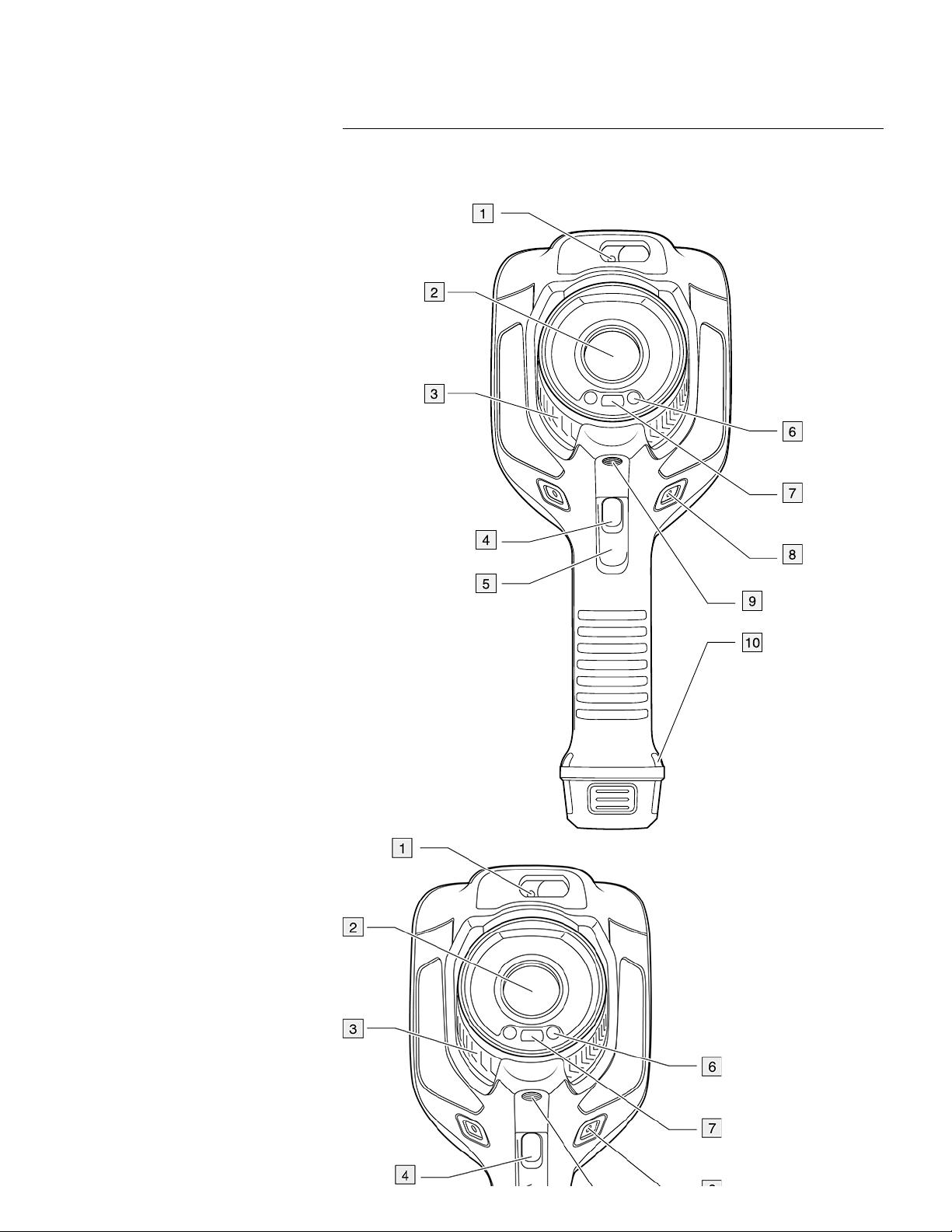
6.1 View from the front
Find Quality Products Online at: sales@GlobalTestSupply.com
www.GlobalTestSupply.com

6
Camera overview
1. Laser distance meter.
1
2. Infrared lens.
3. Focus ring.
4. Autofocus button.
1
5. Trigger.
6. Lamp for the digital camera (left and right sides).
7. Digital camera.
8. Attachment point for the hand strap bracket (left and right sides).
9. Tripod mount.
10. Attachment point for the hand strap, wrist strap, or lanyard strap (left and right sides).
1. This item is dependent on the camera model.
Find Quality Products Online at: sales@GlobalTestSupply.com
www.GlobalTestSupply.com

6
Camera overview
6.2 View from the rear
Find Quality Products Online at: sales@GlobalTestSupply.com
www.GlobalTestSupply.com

6
Camera overview
1. Cover for the USB connector and memory card slot.
2. Microphone.
3. Speaker.
4. Touch-screen LCD.
5. Image archive button.
6. Programmable button.
7. Button to operate the laser.
8. Back button.
9. On/off button.
10. Navigation pad with center push.
11. Battery.
6.3 Laser distance meter and laser pointer
The laser distance meter consists of a laser transmitter and a laser receiver. The laser
transmitter also works as a laser pointer.
Find Quality Products Online at: sales@GlobalTestSupply.com
www.GlobalTestSupply.com

6
1. Laser transmitter.
2. Laser receiver.
Camera overview
6.3.1 Laser transmitter and receiver
6.3.2 Difference in position
This figure shows the difference in position between the laser transmitter and the optical
center of the infrared lens.
2. This item is dependent on the camera model.
Find Quality Products Online at: sales@GlobalTestSupply.com
www.GlobalTestSupply.com
2

6
6.3.3 Laser warning label
A laser warning label with the following information is attached to the camera:
Camera overview
Find Quality Products Online at: sales@GlobalTestSupply.com
www.GlobalTestSupply.com

6
6.3.4 Laser rules and regulations
Wavelength: 650 nm. Maximum output power: 1 mW.
This product complies with 21 CFR 1040.10 and 1040.11 except for deviations pursuant
to Laser Notice No. 50, dated June 24, 2007.
1. Result table.
2. Status icons.
3. Measurement tool (e.g., spotmeter).
4. Temperature scale.
5. Menu system button.
6.4.2 Menu system
To display the menu system, push the navigation pad or tap the menu system button
.
Camera overview
6.4 Screen elements
6.4.1 General
Find Quality Products Online at: sales@GlobalTestSupply.com
www.GlobalTestSupply.com

6
1. Temperature scale button.
2. Measurement parameters button.
3. Image mode button.
4. Measurement button.
5. Color button.
6. Settings button.
7. Main menu.
Battery level
• Green: above 75%
• Yellow: up to 75%
• Red: up to 25%
• No color: below 15%
The remaining storage capacity of the memory card is below 100 MB.
The GPS is enabled.
If the icon is grey, the camera cannot find a GPS signal.
External infrared window compensation is enabled.
The camera is paired with a FLIR Ignite account.
The camera is paired, but does not have contact with FLIR Ignite (no internet
connection).
A Bluetooth headset is connected.
The laser is on.
Camera overview
3
8. Submenu.
6.4.3 Status icons and indicators
6.4.4 Swipe-down menu
To open the swipe-down menu, place your finger at the top of the screen and swipe
down.
3. This item is dependent on the camera model.
Find Quality Products Online at: sales@GlobalTestSupply.com
www.GlobalTestSupply.com

6
1. Storage status of the memory card.
2. Battery status indicator.
3. Bluetooth button: Touch to enable/disable Bluetooth. Touch and hold to open the
Bluetooth settings menu. See also section 21 Pairing Bluetooth devices.
4. Wi-Fi button: Touch to enable/disable Wi-Fi. Touch and hold to open the Wi-Fi settings menu. See also section 20 Configuring Wi-Fi.
5. Ignite upload button: Touch to enable/disable automatic upload of images and videos.
See also section 9.5 Automatic upload.
Note If the camera is not paired with a FLIR Ignite account, you will be prompted to
sign in to FLIR Ignite before you can enable automatic upload.
6. Lamp button: Touch to turn on/off the camera lamp.
Note Before you can turn on the camera lamp, you need to enable the lamp. Select
(Settings) > Device settings > Lamp & laser > Enable lamp & laser or Enable
lamp & laser + Use lamp as flash.
7. Screen brightness slider: Use to control the brightness of the screen.
8. The FLIR Ignite user account that the camera is paired with. For more information,
see section 9.4 Pairing with FLIR Ignite.
9. Storage status of the FLIR Ignite account.
6.4.5 Image overlay information
The image information consists of items such as the date, emissivity, and atmospheric
temperature. All image information is saved in the image file and can be viewed in the image archive. You can also choose to display selected items as image overlay information.
All image overlay information displayed on the live image will also be displayed on saved
images. For more information, see sections section 23.6 Device settings and 11.8 Hiding
all overlay.
Camera overview
Find Quality Products Online at: sales@GlobalTestSupply.com
www.GlobalTestSupply.com

6
6.5 Navigating the menu system
.
6.5.1 Navigating using the navigation pad
You navigate the menu system by using the navigation pad and the back button:
• To display the menu system, push the center of the navigation pad.
• To navigate in menus, submenus, and dialog boxes, and to change values in dialog
boxes, push the navigation pad up/down or left/right.
• To confirm changes and settings in menus and dialog boxes, push the center of the
navigation pad.
Camera overview
You can navigate the menu system in two ways:
• Using your finger or a stylus pen specially designed for capacitive touch usage.
• Using the navigation pad and the back button
Find Quality Products Online at: sales@GlobalTestSupply.com
www.GlobalTestSupply.com

6
.
Camera overview
• To leave dialog boxes and to go back in the menu system, push the back button
Find Quality Products Online at: sales@GlobalTestSupply.com
www.GlobalTestSupply.com

7
Handling the camera
7.1 Charging the battery
7.1.1 General
• Before starting the camera for the first time, charge the battery for 2 hours using the
stand-alone battery charger.
• Select a mains socket that is near the equipment and easily accessible.
7.1.2 Using the stand-alone battery charger to charge the battery
1. Put one or two batteries in the battery charger.
2. Connect the power supply cable plug to the connector on the battery charger.
3. Connect the power supply mains-electricity plug to a mains socket.
4. When the white LED on the battery charger glows continuously, the batteries are fully
charged.
5. It is good practice to disconnect the stand-alone battery charger from the mains
socket when the batteries are fully charged.
7.1.2.1 Stand-alone battery charger LED indicator
Type of signal Explanation
The white LED flashes. The battery is being charged.
The white LED glows continuously. The battery is fully charged.
7.1.3 Using the USB battery charger to charge the battery
1. Put the battery into the battery compartment of the camera.
2. Connect the USB battery charger to a mains socket.
3. Fold up the rubber cover at the top of the camera.
Find Quality Products Online at: sales@GlobalTestSupply.com
www.GlobalTestSupply.com

7
5. To check the status of the battery charging, do one of the following:
• If the camera is turned on: Place your finger at the top of the screen and swipe
down. The battery status is displayed on the swipe-down menu.
• If the camera is turned off: The battery charging indicator is displayed on the
screen.
6. It is good practice to disconnect the USB battery charger from the mains socket when
the battery is fully charged.
Handling the camera
4. Connect the USB connector of the USB battery charger to the USB-C connector in
the connector bay of the camera.
Find Quality Products Online at: sales@GlobalTestSupply.com
www.GlobalTestSupply.com

7
Handling the camera
7.1.4 Charging the battery using a USB cable connected to a computer
1. Fold up the rubber cover at the top of the camera.
Find Quality Products Online at: sales@GlobalTestSupply.com
www.GlobalTestSupply.com

7
Note
• To charge the camera, the computer must be turned on.
• Charging the camera using a USB cable connected to a computer takes considerably
longer than using the USB battery charger or the stand-alone battery charger.
Handling the camera
2. Connect a USB cable to the USB-C connector in the connector bay. Connect the other end of the USB cable to the computer.
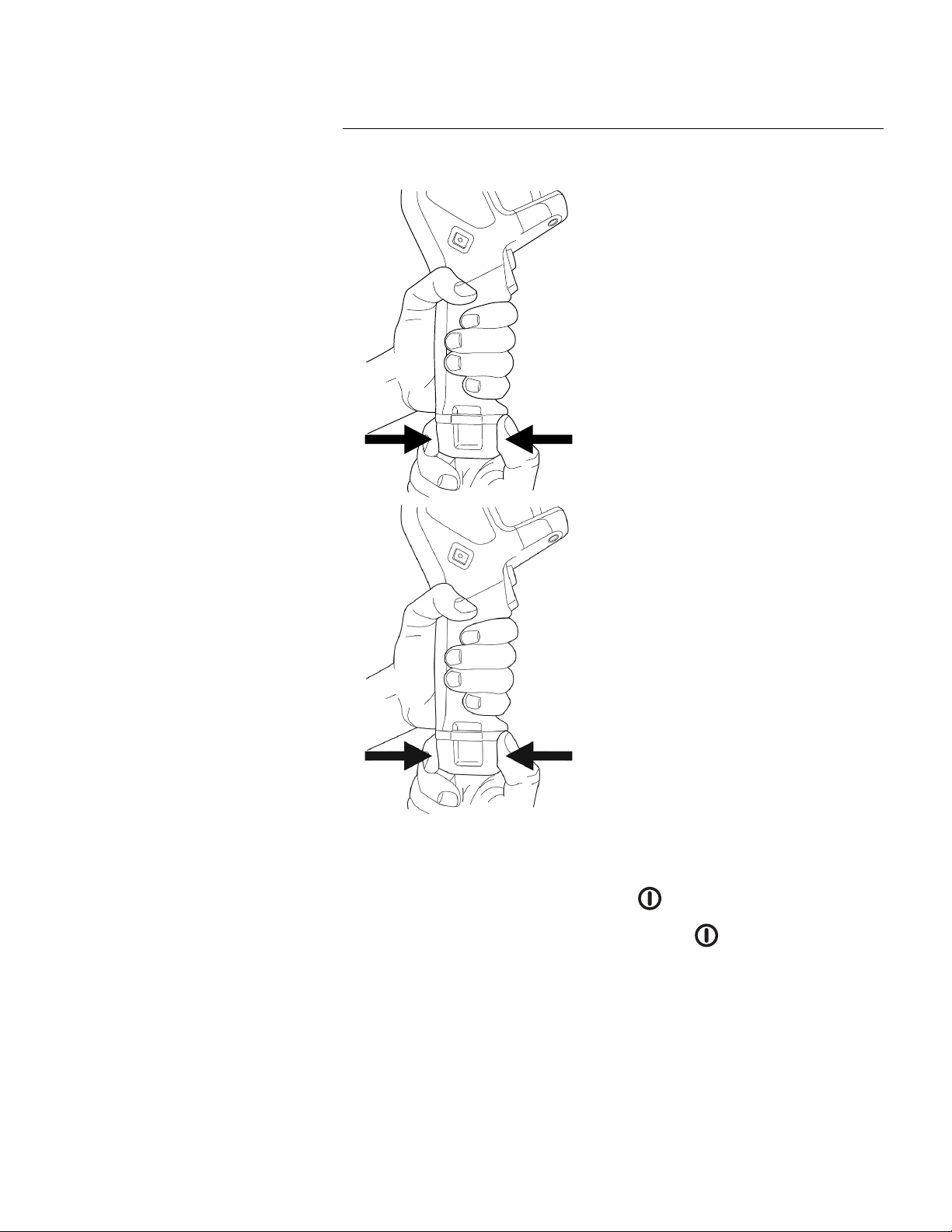
7.2 Removing the battery
1. Turn off the camera.
Find Quality Products Online at: sales@GlobalTestSupply.com
www.GlobalTestSupply.com
7
7.3 Turning on and turning off the camera
.
• To turn off the camera, push and hold the on/off button
for more than 0.5 second.
Note Do not remove the battery to turn off the camera.
Handling the camera
2. Remove the battery from the camera.
• To turn on the camera, push the on/off button
7.4 Adjusting the thermal camera focus
It is very important to adjust the focus correctly. Incorrect focus adjustment affects how
the image modes work. It also affects the temperature measurement.
You can adjust the camera focus by rotating the focus ring or by pushing the autofocus
button. The camera can also be set up to perform continuous autofocusing.
7.4.1 Manual focus
To adjust the focus manually, rotate the focus ring.
Find Quality Products Online at: sales@GlobalTestSupply.com
www.GlobalTestSupply.com

7
Note Do not touch the lens surface when you adjust the focus. If this happens, clean
the lens according to the instructions in 24.2 Infrared lens.
7.4.2 Autofocus
To autofocus the camera, push the Autofocus button.
Handling the camera
Find Quality Products Online at: sales@GlobalTestSupply.com
www.GlobalTestSupply.com

7
Note
• You can also assign the autofocus function to the programmable button. For more information, see section 7.9 Programmable button.
• Autofocus is not supported by all camera models.
7.4.2.1 Autofocus method
When autofocusing, the camera can use one of the following focus methods:
• Contrast: The focus is based on maximizing the image contrast.
• Laser: The focus is based on a laser distance measurement. The laser is used when
the camera is autofocusing.
Handling the camera
Find Quality Products Online at: sales@GlobalTestSupply.com
www.GlobalTestSupply.com

7
(Settings) > Device settings >
Focus > Auto focus and then select Contrast or Laser.
WARNING
When the camera is set to autofocusing with the laser method, do not point the camera at the face of a
person when you use the autofocus function. The laser beam can cause eye irritation.
(Settings) > Device settings > Fo-
cus > Continuous autofocus > On or Off.
WARNING
Do not point the camera at the face of a person when the continuous autofocus function is on. The camera uses laser distance measurements (that are continuous) for the focus adjustments. The laser beam
can cause eye irritation.
WARNING
Do not look directly into the laser beam. The laser beam can cause eye irritation.
Handling the camera
The focus method is configured by a setting. Select
7.4.3 Continuous autofocus
The camera can be set up to perform continuous autofocusing.
When the continuous autofocus function is enabled, the camera bases the focus adjustments on continuous laser distance measurements. The laser is continuously on.
To enable or disable continuous autofocus, select
Note
• Before you can enable continuous autofocus, you need to enable the laser and select
laser as focus method. See section 7.4.2.1 Autofocus method.
• When continuous autofocus is enabled, it is not possible to manually adjust the focus
by rotating the focus ring.
• You can also assign the continuous autofocus function to the programmable button.
For more information, see section 7.9 Programmable button.
• Continuous autofocus is not supported by all camera models.
7.5 Operating the laser distance meter
7.5.1 General
The laser distance meter consists of a laser transmitter and a laser receiver. The laser
distance meter determines the distance to a target by measuring the time it takes for a laser pulse to reach the target and return to the laser receiver. This time is converted to a
distance, which is displayed on the screen.
The laser transmitter also works as a laser pointer. When the laser is on, you will see a
laser dot approximately at the target.
Find Quality Products Online at: sales@GlobalTestSupply.com
www.GlobalTestSupply.com

7
(Settings) > Device settings > Lamp & la-
ser > Enable lamp & laser.
• The symbol
is displayed on the screen when the laser is on.
• The camera can be configured to automatically measure the distance when an image
is saved. Select
(Settings) > Save options & storage > Measure distance. With
this setting, the Object distance parameter (see section 13.5 Changing the measure-
ment parameters) in the image data is automatically updated with the measured distance when an image is saved. (There is no effect on the Object distance setting in
live mode.)
• If the target reflection is low or if the target is angled from the laser beam, there may
be no return signal, and the distance cannot be measured.
• The laser distance meter is not supported by all camera models.
• The laser distance meter may not be enabled in all markets.
7.5.2 Procedure
To operate the laser, do the following:
1. To turn on the laser, push and hold the laser button
. The distance to the target is
displayed on the screen.
2. To turn off the laser, release the laser button
.
Handling the camera
Note
• The laser is enabled by a setting. Select
Find Quality Products Online at: sales@GlobalTestSupply.com
www.GlobalTestSupply.com

7
7.6 Measuring areas
Handling the camera
7.6.1 General
Note The availability of this feature is dependent on the camera model.
The distance measured by the laser distance meter can be used as the basis for area
calculations. A typical application is to estimate the size of a damp stain on a wall.
To measure the area of a surface, you need to lay out a box or circle measurement tool
on the screen. The camera calculates the area of the surface enclosed by the box or
circle tool. The calculation is an estimate of the surface area, based on the measured
distance to the target.
When the laser distance meter is on, you will see a laser dot approximately at the target.
The laser distance meter measures the distance to that target. The camera assumes that
this distance is valid for the entire box or circle tool.
Find Quality Products Online at: sales@GlobalTestSupply.com
www.GlobalTestSupply.com

7
(Settings) >
Device settings > Lamp & laser > Enable lamp & laser.
Follow this procedure:
1. Add a box or circle measurement tool, see section 13.2 Adding/removing measure-
ment tools.
2. Set the camera to measure and display the area of the box or circle, see section 13.6
Displaying values in the result table.
3. Make sure that the box or circle tool is in the center of the image, see section 13.4
Moving and resizing a measurement tool.
4. Adjust the size of the box or circle tool to the size of the target, see section 13.4 Mov-
ing and resizing a measurement tool.
5. Hold the camera perpendicular to the target. Push and hold the laser button
.
6. The calculated area is displayed in the result table.
Handling the camera
For successful area measurements, keep the following in mind:
• Make sure that the box or circle tool is in the center of the image.
• Adjust the size of the box or circle tool to the size of the target.
• Hold the camera perpendicular to the target.
• Avoid targets with many details at different distances from the camera.
7.6.2 Procedure
Note This procedure assumes that you have enabled the laser. Select
7.7 Connecting external devices and storage media
You can connect the following external devices and media to the camera:
• An SD memory card.
• A computer to move image and video files to and from the camera, using a USB-C to
USB-A or a USB-C to USB-C cable.
• A video monitor or projector, using a USB-C to HDMI adapter.
• A USB battery charger.
Note Empty or use a memory card that has not previously been used in another type of
camera. The cameras may organize files differently on the memory card. There is therefore a risk of losing data if the same memory card is used in different types of cameras.
Find Quality Products Online at: sales@GlobalTestSupply.com
www.GlobalTestSupply.com

7
1. LED indicator showing that the memory card is busy.
Note
• Do not eject the memory card when this LED is flashing.
• Do not connect the camera to a computer when this LED is flashing.
2. SD memory card.
3. USB-C cable.
Handling the camera
7.8 Moving files to a computer
When you save an image or video clip in the image archive of the camera, the file is
stored on the memory card.
Find Quality Products Online at: sales@GlobalTestSupply.com
www.GlobalTestSupply.com

7
Handling the camera
You can connect the camera to a computer, using a USB-C to USB-A or a USB-C to
USB-C cable. Once connected, you can move the image and video files from the memory card to the computer.
To move files to a computer via USB cable, do the following:
1. Fold up the rubber cover at the top of the camera.
Find Quality Products Online at: sales@GlobalTestSupply.com
www.GlobalTestSupply.com

7
3. Turn on the camera.
4. Do one of the following:
• Move the files to the computer using a drag-and-drop operation.
Note Moving a file using a drag-and-drop operation does not delete the file in
the camera.
• Import the images into a FLIR Thermography software.
7.8.1 Related topics
You can also set up the camera to upload images for storage online, see section 9 Cloud
connectivity, page 63.
Handling the camera
2. Connect a USB cable to the USB-C connector in the connector bay. Connect the oth-
er end of the USB cable to the computer.
Find Quality Products Online at: sales@GlobalTestSupply.com
www.GlobalTestSupply.com

7
You can assign different functions to the programmable button. You can, for example,
use the programmable button to easily switch between two settings you use often. You
can also choose to define two different setups for saving and previewing: the ordinary
setup for the trigger (which is defined by the Save options and storage settings, see section 23.5 Save options & storage) and another setup for the programmable button.
To assign a function to the programmable button, do the following:
1. Push and hold the programmable button. This displays the Programmable button
menu.
2. Push the navigation pad up/down to select one of the functions. Push the center of
the navigation pad to confirm.
7.9.1 Programmable button options
Available options for the programmable buttons:
• No action: This is the default setting. Nothing will happen when you push the button.
Handling the camera
7.9 Programmable button
Find Quality Products Online at: sales@GlobalTestSupply.com
www.GlobalTestSupply.com

7
Handling the camera
• Switch Auto <> Manual temperature scale: Switch between automatic or manual image adjustment mode. For more information, see section 11.3 Adjusting the infrared
image.
• Autofocus
• Continuous autofocus
functions.
• Hide image overlay graphics: Switch between hide/show all overlay graphics and image overlay information. For more information, see section 11.8 Hiding all overlay.
• Calibrate: Perform a manual NUC. For more information, see section 11.7 Performing
a non-uniformity correction (NUC).
• Auto-adjust the manual temperature scale: Perform an automatic adjustment of the
image while remaining in manual image adjustment mode.
• Switch Thermal <> Digital camera: Switch between the image modes Thermal and
Digital camera. For more information, see section 12 Working with image modes.
• Switch Thermal <> Thermal MSX: Switch between the image modes Thermal and
Thermal MSX. For more information, see section 12 Working with image modes.
• Switch 1x zoom <> Max zoom: Switch between the digital zoom factor of 1× and maximum zoom.
• Switch camera flash On <> Off: Switch between the enabled/disabled camera flash
functions. For more information, see section 7.10 Using the camera lamp as a flash.
Note The flash function will not be activated if the setting Lamp & laser is set to the
option Disable all. For more information, see section 23.6 Device settings.
• Switch single shot <> Video: Switch between the recording modes Single shot and
Video.
• Switch between two latest palettes: Switch between the two last-used color palettes.
For more information, see section 11.5 Changing the color palettes.
• Switch temperature range: Cycle through the camera temperature ranges. For more
information, see section 23.4 Camera temperature range.
• Switch screen rotation On <> Off: Switch between enabled/disabled screen rotation.
• Save: Save an image.
• Save + Prompt for note: Save an image and display the note annotation tool.
• Save + Prompt for table: Save an image and display the table annotation tool.
• Save + Prompt for voice annotation: Save an image and display the voice annotation
tool.
• Save + Prompt for sketch: Save an image and display the sketch annotation tool.
• Save + Select annotation from menu: Save an image and display the annotation tool
menu.
• Preview: Display a preview image.
• Preview + Prompt for note: Display a preview image and the note annotation tool.
• Preview + Prompt for table: Display a preview image and the table annotation tool.
• Preview + Prompt for voice annotation: Display a preview image and the voice annotation tool.
• Preview + Prompt for sketch: Display a preview image and the sketch annotation tool.
• Preview + Select annotation from menu: Display a preview image and the annotation
tool menu.
4
: One-shot autofocus of the infrared camera.
4
: Switch between the enabled/disabled continuous autofocus
7.10 Using the camera lamp as a flash
The camera lamp can be used as a flash for the digital camera. When the flash function
is enabled, the camera lamp will flash when an image is saved by pulling the trigger.
You can also turn on the camera lamp to use it as a flashlight.
Follow this procedure:
1. Push the navigation pad to display the menu system.
4. This item is dependent on the camera model.
Find Quality Products Online at: sales@GlobalTestSupply.com
www.GlobalTestSupply.com

7
(Settings) and push the navigation pad. This displays the Settings menu.
3. Use the navigation pad to select Device settings > Lamp & laser.
4. To use the camera lamp as a flash, do one of the following:
• To enable the camera lamp function, select Enable lamp & laser and push the navigation pad. To turn on/off the camera lamp, use the swipe-down menu, see section 6.4.4 Swipe-down menu.
• To enable the flash function, select Enable lamp & laser + Use lamp as flash and
push the navigation pad.
• To disable the camera lamp and flash functions, select Disable all and push the
navigation pad.
Note You can also assign the function Switch camera flash On <> Off to the program-
mable button. For more information, see section 7.9 Programmable button.
Handling the camera
2. Select
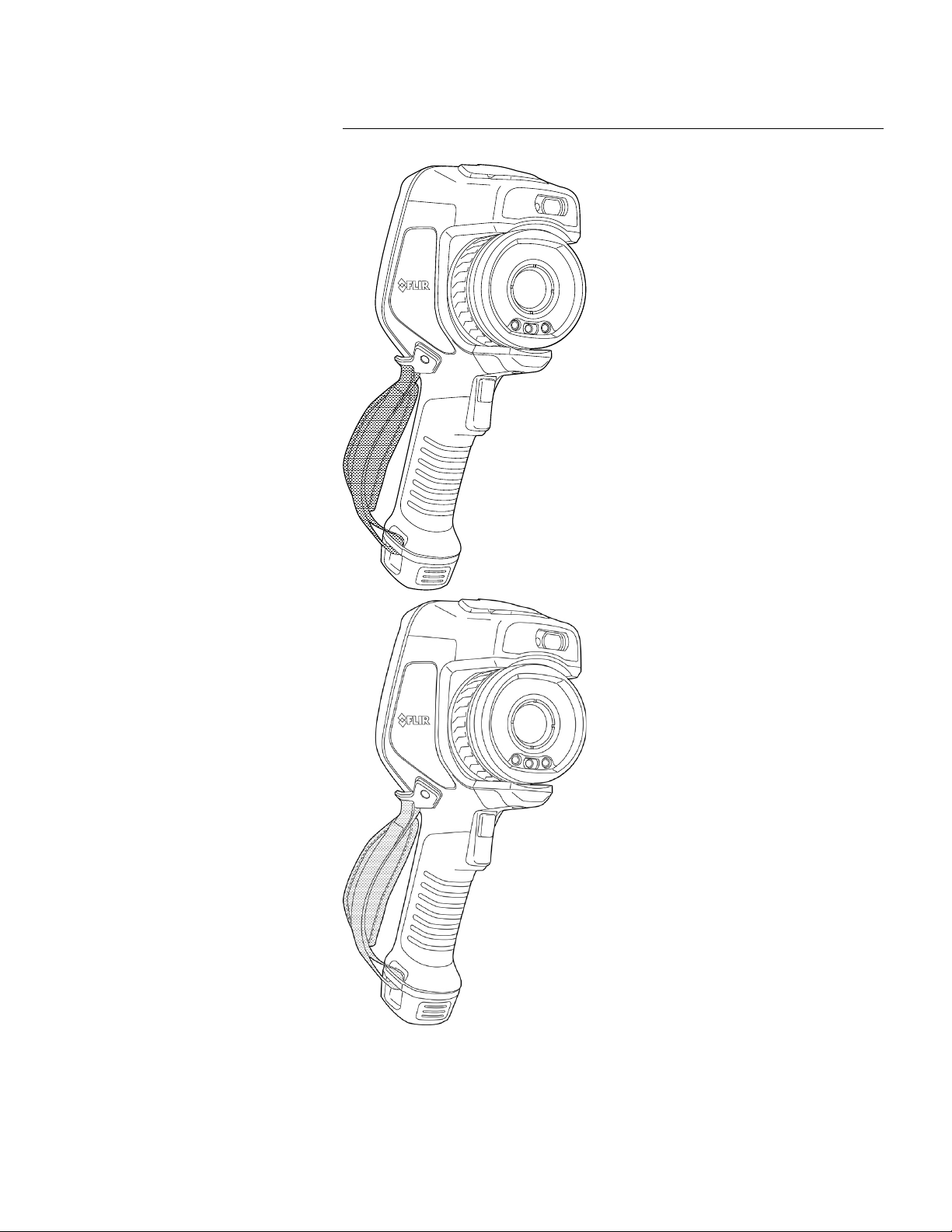
7.11 Hand strap
The upper part of the hand strap is attached to the camera by a bracket. There is one
bracket for the left side and one for the right side of the camera.
The lower part of the hand strap is threaded through the attachment point at the base of
the camera.
Find Quality Products Online at: sales@GlobalTestSupply.com
www.GlobalTestSupply.com
7
Handling the camera
Find Quality Products Online at: sales@GlobalTestSupply.com
www.GlobalTestSupply.com

7
Handling the camera
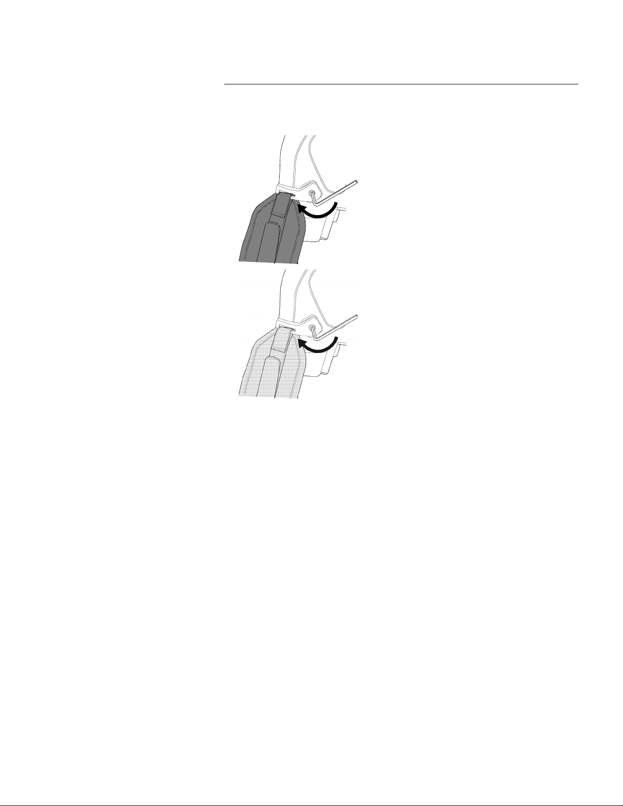
7.11.1 Mounting the hand strap
1. Fit the upper part of the hand strap into the bracket.
Find Quality Products Online at: sales@GlobalTestSupply.com
www.GlobalTestSupply.com
7
Handling the camera
2. Fit the bracket in place on the camera and tighten the screw with the supplied Torx
key.
Find Quality Products Online at: sales@GlobalTestSupply.com
www.GlobalTestSupply.com

7
Handling the camera
3. Thread the loose strap through the attachment point at the base of the camera. Secure the strap with the hook-and-loop fastener.
Find Quality Products Online at: sales@GlobalTestSupply.com
www.GlobalTestSupply.com

7
Handling the camera
7.12 Lanyard strap
Find Quality Products Online at: sales@GlobalTestSupply.com
www.GlobalTestSupply.com

7
3. Pull the entire lanyard strap through the attachment point until it stops.
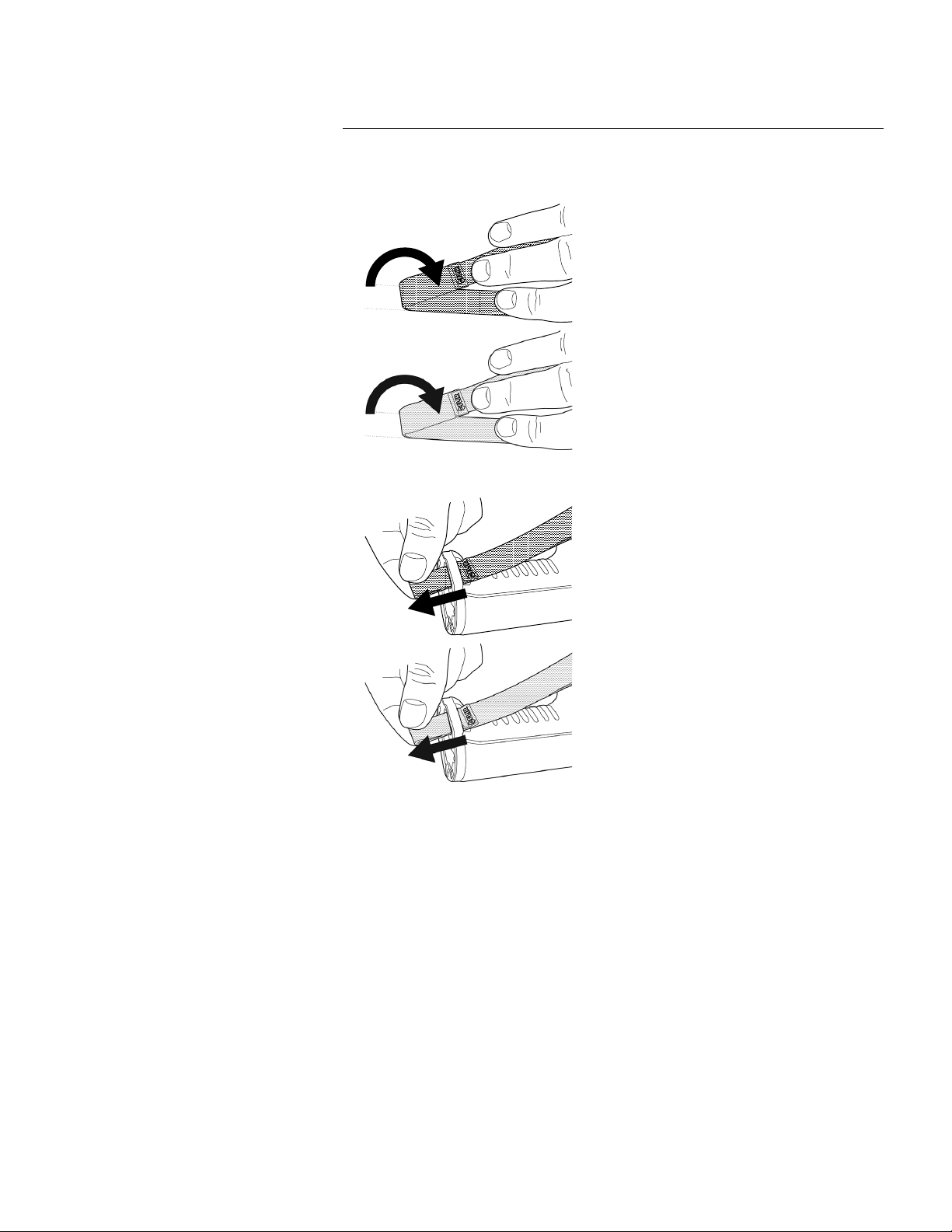
7.13 Wrist strap
Handling the camera
To mount the lanyard strap, do the following:
1. Remove the camera battery.
2. Starting with the FLIR logo part, thread the lanyard strap through the attachment
point at the base of the camera.
The wrist strap can also be used to attach a carabiner to the camera.
Find Quality Products Online at: sales@GlobalTestSupply.com
www.GlobalTestSupply.com

7
To mount the wrist strap, do the following:
1. Remove the camera battery.
Handling the camera
Find Quality Products Online at: sales@GlobalTestSupply.com
www.GlobalTestSupply.com
7
3. Thread the bent wrist strap through the attachment point at the base of the camera.
Handling the camera
2. Fold the wrist strap. Make sure that the part with the FLIR logo faces away from the
bend.
Find Quality Products Online at: sales@GlobalTestSupply.com
www.GlobalTestSupply.com

7
7.14 Front protection
Handling the camera
4. Pull the entire wrist strap through the attachment point until it stops.
To protect the camera lens and the laser distance meter, you can attach the front protection by using the supplied fastening device.
Find Quality Products Online at: sales@GlobalTestSupply.com
www.GlobalTestSupply.com

7
7.15 Changing camera lenses
Handling the camera
Applicability: Camera models with an exchangeable lens.
Note If the new lens has not been used with the camera before, the lens–camera com-
bination must be calibrated after the lens has been mounted. See section 7.16 Calibrating the lens–camera combination for information on how to do this.
Find Quality Products Online at: sales@GlobalTestSupply.com
www.GlobalTestSupply.com

7
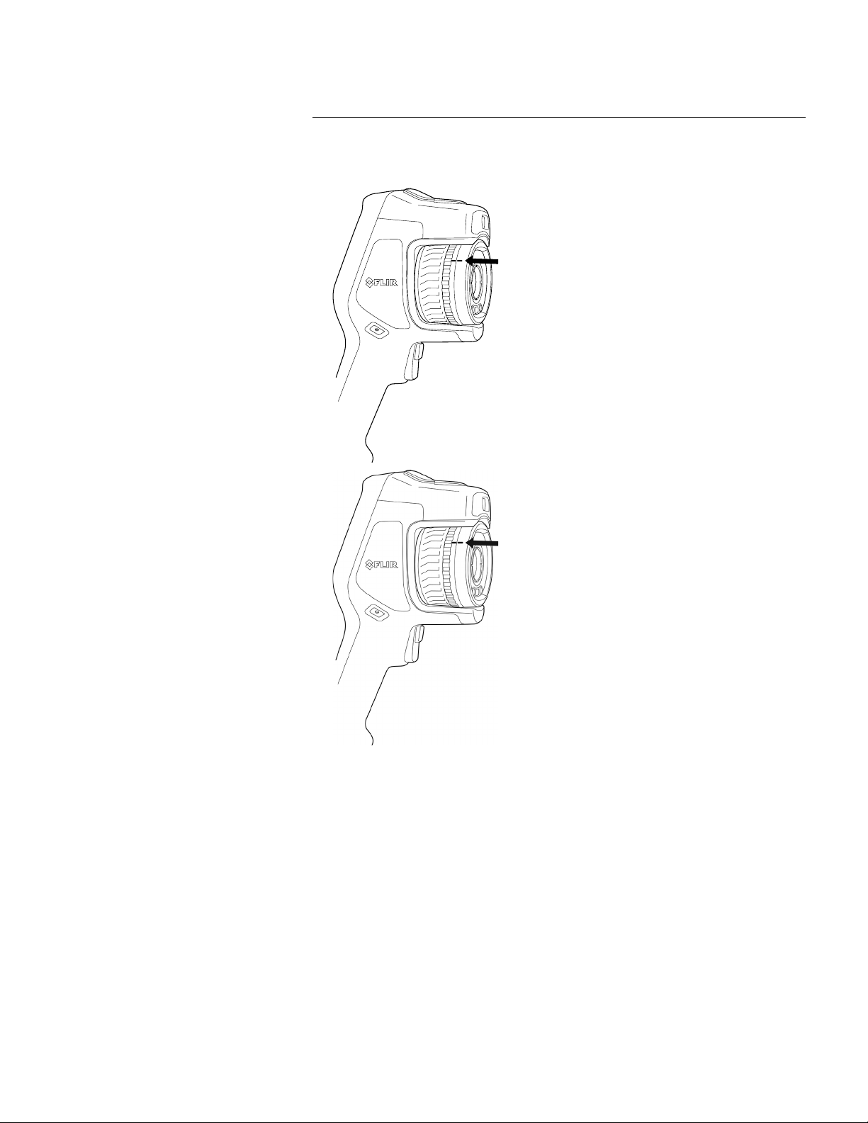
2. Carefully pull out the lens.
Handling the camera
Note Do not touch the lens surface when you change lenses. If this happens, clean the
lens according to the instructions in 24.2 Infrared lens.
Follow this procedure:
1. Take a firm grip around the inner ring of the lens. Rotate the inner ring 30° counterclockwise until it stops.
Find Quality Products Online at: sales@GlobalTestSupply.com
www.GlobalTestSupply.com

7
Handling the camera
3. The infrared detector is now fully exposed. Do not touch this surface. If you see dust
on the detector, follow the instructions in 24.3 Infrared detector.
Find Quality Products Online at: sales@GlobalTestSupply.com
www.GlobalTestSupply.com

7
• Wrong: You must rotate the inner ring until the tooth (1) reaches the black stop pin
(2).
Handling the camera
4. Make sure that the inner ring of the camera lens is fully in its open position.
• Correct: The tooth (1) is in its end position at the black stop pin (2).
Find Quality Products Online at: sales@GlobalTestSupply.com
www.GlobalTestSupply.com

7
6. Rotate the inner ring of the lens 30° clockwise. The lens makes a click when it locks
in place.
Handling the camera
5. Carefully push the lens into position.
Find Quality Products Online at: sales@GlobalTestSupply.com
www.GlobalTestSupply.com
7
7.16 Calibrating the lens–camera combination
Handling the camera
7. Make sure that the two index marks are aligned, indicating that the lens is locked in
place.
Applicability: Camera models with an exchangeable lens.
7.16.1 Introduction
Before a new lens can be used with the camera, the lens–camera combination must be
calibrated.
This is a process that previously had to be performed by a FLIR service department, but
for the FLIR Exx series the calibration can be performed by the user. This feature is
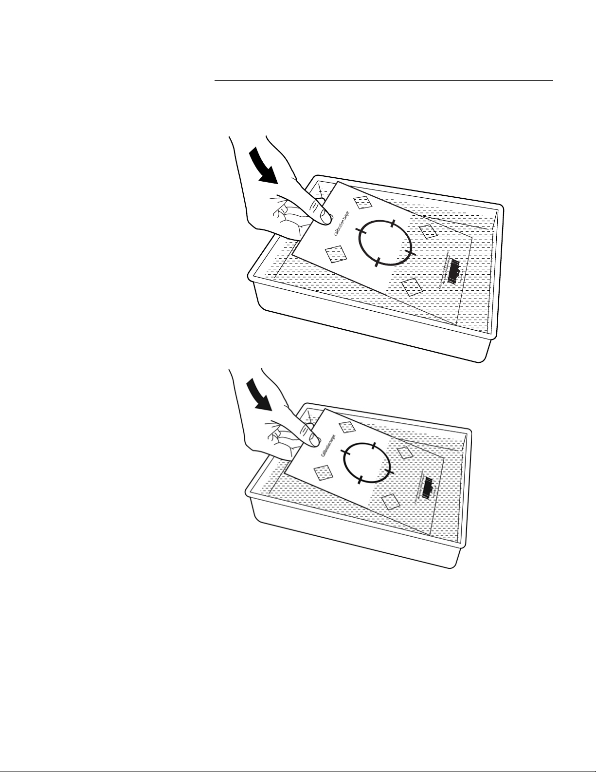
called AutoCal. The AutoCal procedure requires a calibration target, which is included in
the lens package.
Note For lenses that ship with the camera, the lens–camera combination is factory
calibrated.
Find Quality Products Online at: sales@GlobalTestSupply.com
www.GlobalTestSupply.com
7
Handling the camera
7.16.2 AutoCal procedure
1. Dip the calibration target in water for 1 second and let the excess drip off.
Find Quality Products Online at: sales@GlobalTestSupply.com
www.GlobalTestSupply.com

7
3. Mount the new lens on the camera according to the procedure in section 7.15
Changing camera lenses. When the lens is mounted, the calibration wizard starts
automatically.
Handling the camera
2. Tape or hang the calibration target on a wall.
Find Quality Products Online at: sales@GlobalTestSupply.com
www.GlobalTestSupply.com

7
Handling the camera
4. From a distance of 2 m (6.6 ft.), aim the camera toward the crosshair, using the laser
pointer. The camera will take a picture automatically.
Note Make sure the camera’s optical path is perpendicular to the calibration target.
See the image below.
Find Quality Products Online at: sales@GlobalTestSupply.com
www.GlobalTestSupply.com
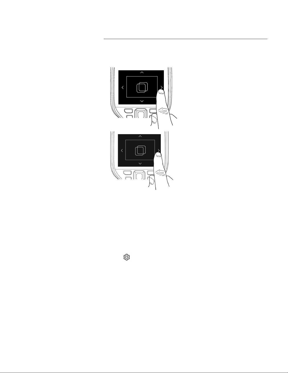
7
To repeat the procedure at a later time, go to Settings > Device settings > Camera infor-
mation > Calibration > Calibrate lens....
(Settings) and push the navigation pad. This displays the Settings menu.
3. Use the navigation pad to select Device settings > Geolocation > Compass.
4. Make sure the compass is enabled by toggling the switch.
5. Select Calibrate compass and push the navigation pad. Follow the on-screen
instructions.
Note You must rotate the camera slowly.
Handling the camera
5. In the camera, align the thermal and visual images (indicated by the two squares in
the image below), using the touchscreen arrows. The lens–camera combination is
now calibrated.
7.17 Calibrating the compass
It is recommended that the compass is calibrated every time you move the camera to a
new location.
Follow this procedure:
1. Push the navigation pad to display the menu system.
2. Select
Find Quality Products Online at: sales@GlobalTestSupply.com
www.GlobalTestSupply.com

8
(Settings) > Save options & storage > Photo as separate JPEG = On.
• When the Digital camera image mode is selected, a high-resolution digital image is
stored when an image is saved. However, no thermal information is stored. For more
information, see section 12 Working with image modes.
• You can choose to turn off the digital camera. This can, for example, be required in re-
stricted areas and in confidential (e.g., doctor/patient) situations. Select
(Settings)
> Save options & storage > Digital camera = Off. When the digital camera is off, features that require visual information, such as the images modes Thermal MSX and
Picture in picture, are disabled.
8.1.2 File-naming convention
The default naming convention for image files is FLIRxxxx.jpg, where xxxx is a unique
counter.
It is also possible to save images with a date prefix added to the filename. However,
these files may not automatically be detected by third-party applications. For more information, see the setting File naming format in section 23.5 Save options & storage.
8.1.3 Storage capacity
When you save an image, the camera stores the image file on the memory card.
The size of an image file (with no annotations) is typically less than 1000 kB. Thus, the
capacity of a 8 GB memory card is approximately 8000 images.
Note Empty or use a memory card that has not previously been used in another type of
camera. The cameras may organize files differently on the memory card. There is therefore a risk of losing data if the same memory card is used in different types of cameras.
8.1.4 About UltraMax
Note The availability of this feature is dependent on the camera model.
UltraMax is an image enhancement feature that increases the image resolution and lowers the noise, making small objects easier to see and measure. An UltraMax image is
twice as wide and high as an ordinary image.
When an UltraMax image is captured by the camera, several ordinary images are saved
within the same file. Capturing all the images can take up to 1 second. To fully utilize UltraMax, the images need to be slightly different, which can be accomplished by a minute
movement of the camera. You should hold the camera firmly in your hands (do not put it
on a tripod), which will make these images vary just a little during the capture. Correct focus, a high-contrast scene, and a non-moving target are other conditions that help to
achieve a good-quality UltraMax image.
Saving and working with images
8.1 About image files
8.1.1 General
When you save an image, the camera saves an image file that includes all thermal and
visual information. This means that you can open an image file at a later time and, for example, select another image mode, apply color alarms, and add measurement tools.
The image *.jpg file is fully radiometric and saved lossless, which enables full post-processing in image analysis and reporting software from FLIR Systems. There is also a regular *.jpg component (lossy) for convenient viewing in non-FLIR Systems software (e.g.,
Microsoft Explorer).
Note
• The camera can also be configured to save an extra low-resolution visual image as a
separate file. This can be convenient if you are not using a post-processing software.
Select
Find Quality Products Online at: sales@GlobalTestSupply.com
www.GlobalTestSupply.com
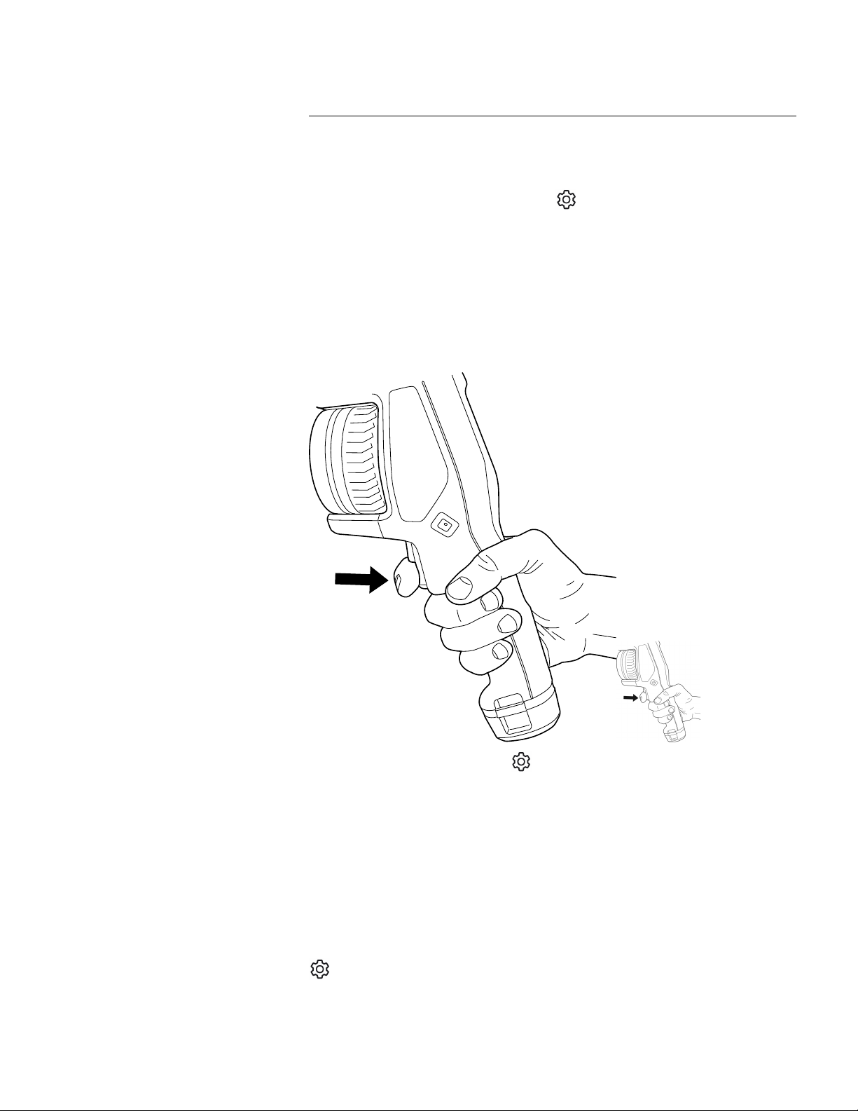
8
(Settings) > Save options & storage >
Image resolution = UltraMax.
Note Depending on the settings in (Settings) > Save options & storage, the follow-
ing may also happen:
• A preview image is displayed before the image is saved.
• An annotation tool or the annotation menu is displayed when the image has been
saved.
(Settings) > Save options & storage > Preview image before saving = On.
To preview an image, do the following:
1. To preview an image, pull the trigger. This displays the preview.
2. Manual image adjustment mode is now active. For image adjustment instructions,
see section 11.3 Adjusting the infrared image.
Saving and working with images
Some FLIR Thermography software has the ability to process UltraMax images. Other
FLIR software will treat the image as a regular image.
To configure the camera for UltraMax, select
8.2 Saving an image
When you save an image, the camera stores the image file in the camera memory.
Note You can also set up the camera to upload images for storage online, see section
9 Cloud connectivity.
To save an image, pull the trigger.
8.3 Previewing an image
You can preview an image before you save it. This enables you to see if the image contains the information you want before you save it. You can also adjust and edit the image.
Note The camera must be configured to display a preview image before saving. Select
Find Quality Products Online at: sales@GlobalTestSupply.com
www.GlobalTestSupply.com

8
.
. This displays the Gallery with one or more
folders.
2. Select a folder and push the navigation pad.
3. Select the image you want to view and push the navigation pad.
4. Do one or more of the following:
• To view the previous/next image, push the navigation pad left/right.
• To display a toolbar at the top of the screen, push the navigation pad. Do one or
more of the following:
◦ To switch between an infrared image and a visual image, select the
icon
and push the navigation pad.
◦ To edit the image, delete the image, display information, or add annotations, se-
lect the
icon and push the navigation pad. This displays a menu to the right.
• To return to the folder overview, push the back button
.
• To return to the live image, push the image archive button
.
. This displays the Gallery.
2. Select a folder and push the navigation pad.
3. Select the image you want to edit and push the navigation pad.
4. Push the navigation pad to display the top toolbar.
5. On the top toolbar, select the
icon and push the navigation pad.
6. On the right toolbar, select the
icon and push the navigation pad. This opens the
image in edit mode.
7. Manual image adjustment mode is now active. For image adjustment instructions,
see section 11.3 Adjusting the infrared image.
Saving and working with images
3. To edit the image, push the navigation pad. This displays a context menu. For editing
instructions, see section 8.5 Editing a saved image.
4. Do one of the following:
• To save the image, pull the trigger.
• To exit preview mode without saving, push the back button
8.4 Opening a saved image
When you save an image, the image file is stored on the memory card. To display the image again, open it from the image archive (Gallery).
To open a saved image, do the following:
1. Push the image archive button
8.5 Editing a saved image
You can edit a saved image. You can also edit an image in preview mode.
To edit a saved image, do the following:
1. Push the image archive button
Find Quality Products Online at: sales@GlobalTestSupply.com
www.GlobalTestSupply.com

8
(Cancel) to exit edit mode.
• Select
(Measurement parameters) to change the global parameters.
• Select
(Image mode) to change the image mode.
• Select
(Measurement) to add a measurement tool.
• Select
(Color) to change the color palette or set a color alarm.
• Select
(Save) to save and exit edit mode.
9. To store the edited image online, make a manual upload of the image. See section
9.6 Manual upload.
8.5.1 Related topics
• 11.6 Changing the measurement parameters.
• 12 Working with image modes.
• 13 Working with measurement tools.
• 11.5 Changing the color palettes.
• 14 Working with color alarms and isotherms.
. This displays the Gallery.
2. Select a folder and push the navigation pad.
3. Select an image and push the navigation pad.
4. Push the navigation pad to display the top toolbar.
5. On the top toolbar, select the
icon and push the navigation pad.
6. On the right toolbar, select the
icon and push the navigation pad. This displays
the image information.
Saving and working with images
8. Push the navigation pad. This displays a context menu.
• Select
8.6 Displaying the image information
The image information consists of items such as the date, emissivity, and atmospheric
temperature. When you save an image, the image information is saved in the image file
and can be viewed in the image archive (Gallery).
To display the image information, do the following:
1. Push the image archive button
8.7 Zooming an image
You can zoom an image by using the camera’s digital zoom function. You can do this on
live images and on saved images in edit mode.
The digital zoom factor is displayed at the top of the screen.
To digitally zoom an image, do the following:
• Zoom in: Touch the screen with two fingers and spread the fingers apart.
• Zoom out: Touch the screen with two fingers and pinch the fingers together.
8.8 Deleting images
You can delete image files from the memory card. For more information, see sections
10.9 Deleting an image or video file, 10.10 Deleting multiple files, and 10.11 Deleting all
files.
Find Quality Products Online at: sales@GlobalTestSupply.com
www.GlobalTestSupply.com

8
(Settings) and push the navigation pad. This displays the Settings menu.
3. Use the navigation pad to select Device settings > Reset options > Reset image
counter....
4. Push the navigation pad. This displays a dialog box.
5. To reset the counter, select Reset and push the navigation pad.
Saving and working with images
8.9 Resetting the image counter
You can reset the numbering of the image filenames.
Note To prevent image files being overwritten, the new counter value will be based on
the highest existing filename number in the image archive. To ensure that the counter is
reset to 0001, insert an empty memory card before resetting the counter.
Follow this procedure:
1. Push the navigation pad to display the menu system.
2. Select
Find Quality Products Online at: sales@GlobalTestSupply.com
www.GlobalTestSupply.com

9
(Settings) > Connections > Wi-Fi > Connect to network.
2. To display a list of the available networks, select Available networks.
3. Select one of the available networks and push the navigation pad.
Note Password-protected networks are indicated with a padlock icon, and for these
you will need to enter a password the first time you connect to the network. After that
the camera will connect automatically to the network. To disable the automatic connection, select Forget network.
Note To enable/disable the camera firewall, select Connections > Advanced >
Global firewall.
9.2.2 Connecting via Bluetooth
If supported by your mobile phone, you can share the phone’s internet connection with
the camera via Bluetooth.
Note The Bluetooth protocol is limited in terms of data transfer and best suited for upload of single images. For upload of videos and folders with several images, it is recommended to use Wi-Fi.
To connect the camera to the internet via your mobile phone, do the following:
1. Select
(Settings) > Connections > Bluetooth.
2. Make sure Bluetooth is enabled by toggling the Bluetooth switch.
Note On the mobile phone, you must make sure that Bluetooth is enabled, that the
phone is in discovery mode, and that Bluetooth tethering is enabled.
3. Select Available devices and push the navigation pad.
4. Wait until a list of available Bluetooth devices is displayed.
5. Select your mobile phone and begin the pairing procedure.
Cloud connectivity
FLIR Ignite is a cloud storage service for thermal images. Upload images from your camera and your data will be instantly available across all your devices. With FLIR Ignite you
can edit images and create basic reports. You can also share images with colleagues
and clients and invite team members to work in the same folder and files.
FLIR Ignite also includes a PC–based application called FLIR Ignite Sync that allows you
to sync your image library with your computer. This gives you easy access to images
when creating reports in FLIR Thermal Studio or other post-processing software.
9.1 Uploading to FLIR Ignite
You can set up the camera to upload images and videos to FLIR Ignite.
If automatic upload is enabled, new images and videos will automatically be uploaded to
the FLIR Ignite account. You can also upload images and videos manually from the image archive.
To be able to upload images and videos, you need to connect the camera to the internet
and pair the camera with a FLIR Ignite account.
9.2 Connecting to internet
You can connect the camera to the internet via Wi-Fi or Bluetooth.
9.2.1 Connecting to Wi-Fi
You can connect the camera to a Wi-Fi network as part of the initial setup of the camera.
You can also connect the camera at any time via the Settings menu.
To connect to Wi-Fi via the Settings menu, do the following:
1. Select
Find Quality Products Online at: sales@GlobalTestSupply.com
www.GlobalTestSupply.com

9
(Settings) > FLIR Ignite.
3. Start the pairing procedure by selecting Sign in.
4. Use a computer or other device with internet access and go to the website displayed
on the camera screen.
5. On the website, enter the code displayed on the camera screen.
6. Sign in to your FLIR Ignite account.
(Settings) > FLIR Ignite.
3. Enable/disable automatic upload by toggling the Auto upload switch.
Note You can also enable automatic upload on the swipe-down menu. For more information, see section 6.4.4 Swipe-down menu.
.
4. Select a folder and then select an image or video.
5. Push the navigation pad to display the top toolbar.
6. On the top toolbar, select the
icon.
7. On the right toolbar, select the
icon.
9.6.2 Uploading multiple files
1. Make sure the camera is connected to the internet.
2. Make sure the camera is paired with a FLIR Ignite account.
3. Push the image archive button
.
Cloud connectivity
9.3 Creating a FLIR Ignite account
To create a FLIR Ignite account, go to and click Sign up.
9.4 Pairing with FLIR Ignite
You can pair the camera as part of the initial setup of the camera. You can also pair the
camera at any time via the Settings menu.
To pair the camera via the Settings menu, do the following:
1. Make sure the camera is connected to the internet.
2. Select
9.5 Automatic upload
You can set up the camera to automatically upload images and videos to your FLIR Ignite
account.
When automatic upload is enabled, new images and videos will automatically be uploaded when the camera is connected to the internet and paired with FLIR Ignite.
To enable automatic upload, do the following:
1. Make sure the camera is paired with your FLIR Ignite account.
2. Select
9.6 Manual upload
You can manually upload images, videos, and folders from the image archive when the
camera is paired with a FLIR Ignite account and connected to the internet.
You can monitor the upload progress at the top of the image archive.
9.6.1 Uploading an image/video file
1. Make sure the camera is connected to the internet.
2. Make sure the camera is paired with a FLIR Ignite account.
3. Push the image archive button
Find Quality Products Online at: sales@GlobalTestSupply.com
www.GlobalTestSupply.com

9
icon.
6. Select the images and videos you want to upload. Selected files are marked with a
tick.
7. On the right toolbar, select the
icon.
9.6.3 Uploading folders
1. Make sure the camera is connected to the internet.
2. Make sure the camera is paired with a FLIR Ignite account.
3. Push the image archive button
.
4. On the top toolbar, select the
icon.
5. Select the folders you want to upload. Selected folders are marked with a tick.
6. On the right toolbar, select the
icon.
Cloud connectivity
4. Select a folder.
5. On the top toolbar, select the
9.7 Accessing FLIR Ignite
You can access FLIR Ignite from a browser on your desktop, tablet, or mobile device.
To access FLIR Ignite, go to
For more information, refer to the FLIR Ignite user manual.
Find Quality Products Online at: sales@GlobalTestSupply.com
www.GlobalTestSupply.com

10
. This displays the Gallery with one or more
folders.
2. Select a folder and push the navigation pad.
3. Select the image or video clip you want to view and push the navigation pad.
4. Do one or more of the following:
• To view the previous/next image or video clip, push the navigation pad left/right.
• To display a toolbar at the top of the screen, push the navigation pad. Do one or
more of the following:
Images:
◦ To switch between an infrared image and a visual image, select the
icon
and push the navigation pad.
◦ To edit the image, delete the image, display information, or add annotations, se-
lect the
icon and push the navigation pad. This displays a menu to the right.
Video clips:
◦ Select the
icon and push the navigation pad. To play or pause the video
clip, push the navigation pad.
◦ To delete the video or display information, select the
icon and push the
navigation pad. This displays a menu to the right.
5. To return to the folder overview, push the back button
.
6. To return to the Gallery, push the back button
again.
. This displays the Gallery.
2. On the top toolbar, select the
icon and push the navigation pad.
3. A soft keyboard is displayed, where you can enter the name of the folder by touching
the screen.
4. When completed, touch Done on the soft keyboard.
5. The new folder automatically becomes the active folder and appears at the top of the
Gallery.
Working with the image archive
10.1 General
When you save an image or video clip, the camera stores the image/video file in the image archive on the memory card. You can open an image in the image archive and, for
example, select another image mode, apply color alarms, and add measurement tools.
You can also open and play saved video clips.
In the camera, the image archive is called Gallery. The Gallery can include one or several
folders. New images and video clips will be saved to the active folder, at the top of the
Gallery. You can create new folders, rename a folder, change the active folder, move files
between the folders, and delete folders.
10.2 Opening image and video files
1. Push the image archive button
10.3 Creating a new folder
1. Push the image archive button
Find Quality Products Online at: sales@GlobalTestSupply.com
www.GlobalTestSupply.com

Working with the image archive10
. This displays the Gallery.
2. On the top toolbar, select the
icon and push the navigation pad.
3. Select the folder to rename and push the navigation pad.
4. On the right toolbar, select the
icon and push the navigation pad.
5. A soft keyboard is displayed, where you can enter the new name of the folder by
touching the screen.
6. When completed, touch Done on the soft keyboard.
. This displays the Gallery.
2. On the top toolbar, select the
icon and push the navigation pad.
3. Select the folder that new images and video clips should be saved to and push the
navigation pad. This marks the selected folder with a tick.
4. On the right toolbar, select the
icon and push the navigation pad.
5. The selected folder is moved to the top of the Gallery.
. This displays the Gallery.
2. Select a folder and push the navigation pad.
3. On the top toolbar, select the
icon and push the navigation pad.
4. Use the navigation pad to select the image and video items you want to move. You
can also select the items by touching the screen. Selected items are marked with a
tick.
5. On the right toolbar, select the
icon and push the navigation pad.
6. Select the destination folder for the selected items and push the navigation pad.
. This displays the Gallery.
2. On the top toolbar, select the
icon and push the navigation pad.
3. Select the folder to delete and push the navigation pad.
10.4 Renaming a folder
You can change the name of the folders in the archive. The active folder cannot be
renamed.
To rename a folder, do the following:
1. Push the image archive button
10.5 Changing the active folder
New images and video clips are saved to the active folder.
To change the active folder, do the following:
1. Push the image archive button
10.6 Moving files between folders
1. Push the image archive button
10.7 Uploading files and folders
You can manually upload images, videos, and folders to your FLIR Ignite account when
the camera is connected to the internet. For more information, see section 9.6 Manual
upload.
10.8 Deleting a folder
You can delete a folder in the archive. The active folder cannot be deleted.
1. Push the image archive button
Find Quality Products Online at: sales@GlobalTestSupply.com
www.GlobalTestSupply.com

Working with the image archive10
icon and push the navigation pad. This displays a
dialog box.
5. To delete the folder, select Delete and push the navigation pad.
. This displays the Gallery.
2. Select a folder and push the navigation pad.
3. Select the image or video clip you want to delete and push the navigation pad.
4. Push the navigation pad to display the top toolbar.
5. On the top toolbar, select the
icon and push the navigation pad.
6. On the right toolbar, select the
icon and push the navigation pad. This displays a
dialog box.
7. To delete the image, select Delete and push the navigation pad.
. This displays the Gallery.
2. Select a folder and push the navigation pad.
3. On the top toolbar, select the
icon and push the navigation pad.
4. Use the navigation pad to select the image and video items you want to delete. You
can also select the items by touching the screen. Selected items are marked with a
tick.
5. On the right toolbar, select the
icon and push the navigation pad. This displays a
dialog box.
6. To delete the selected items, select Delete and push the navigation pad.
(Settings) and push the navigation pad. This displays the Settings menu.
3. Use the navigation pad to select Save options & storage > Delete all saved files... .
4. Push the navigation pad. This displays a dialog box.
5. To permanently delete all saved files, select Delete and push the navigation pad.
4. On the right toolbar, select the
10.9 Deleting an image or video file
You can delete an image or video file from the image archive.
Note When deleting an image file, both images in the image file (thermal and visual)
will be deleted.
1. Push the image archive button
10.10 Deleting multiple files
You can delete multiple image and video files from the image archive.
1. Push the image archive button
10.11 Deleting all files
You can delete all image and video files from the memory card.
1. Push the navigation pad to display the menu system.
2. Select
Find Quality Products Online at: sales@GlobalTestSupply.com
www.GlobalTestSupply.com
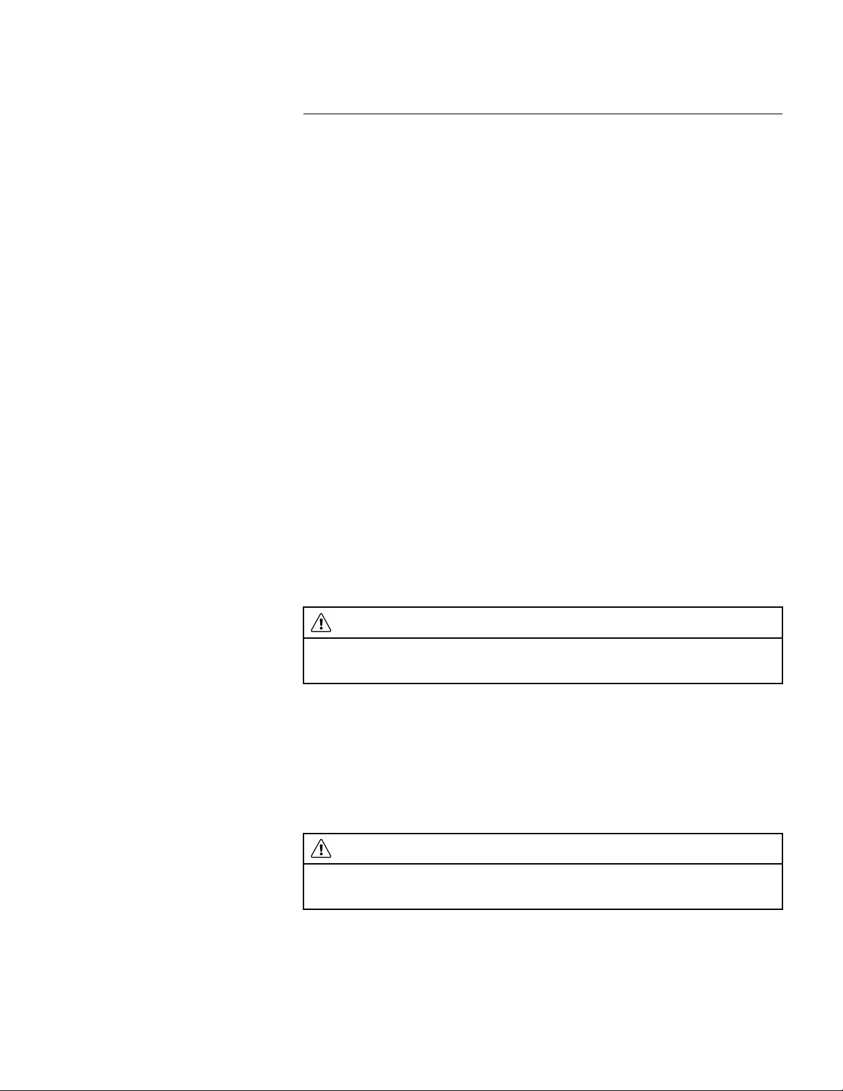
11
WARNING
When the camera is set to autofocusing with the laser method (Settings > Device settings > Focus > Auto focus >Laser), do not point the camera at the face of a person when you use the autofocus function.
The laser beam can cause eye irritation.
WARNING
Do not point the camera at the face of a person when the continuous autofocus function is on. The camera uses laser distance measurements (that are continuous) for the focus adjustments. The laser beam
can cause eye irritation.
Achieving a good image
11.1 General
A good image depends on several different functions and settings, although some functions and settings affect the image more than others.
These are the functions and settings that you need to experiment with:
• Adjusting the infrared camera focus.
• Adjusting the infrared image (automatically or manually).
• Selecting a suitable temperature range.
• Selecting a suitable color palette.
• Changing the measurement parameters.
• Performing a non-uniformity correction (NUC).
The following sections explain how to work with these functions and settings.
In some situations, you may also want to hide the overlay graphics for a better view.
11.2 Adjusting the infrared camera focus
It is very important to adjust the focus correctly. Incorrect focus adjustment affects how
the image modes work. It also affects the temperature measurement.
11.2.1 Manual focus
You can adjust the focus manually by rotating the focus ring. For more information, see
section 7.4.1 Manual focus.
11.2.2 Autofocus
You can autofocus the infrared camera by pushing the Autofocus button. For more information, see section 7.4.2 Autofocus.
Note
• You can also assign the autofocus function to the programmable button. For more information, see section 7.9 Programmable button.
• Autofocus is not supported by all camera models.
11.2.3 Continuous autofocus
The infrared camera can be set up to perform continuous autofocusing. For more information, see section 7.4.3 Continuous autofocus.
Note Continuous autofocus is not supported by all camera models.
11.3 Adjusting the infrared image
11.3.1 General
An infrared image can be adjusted automatically or manually.
Find Quality Products Online at: sales@GlobalTestSupply.com
www.GlobalTestSupply.com

Achieving a good image11
(Settings) > Device settings > User interface options > Auto adjustment method.
By using the Auto adjustment region feature it is possible to select an area of the image,
and then have the colorization of the image adjusted based on the temperatures within
that selected area. For more information, see section 11.3.2 Auto adjustment region.
In manual mode, you can adjust the temperature scale to values close to the temperature
of a specific object in the image. This will make it possible to detect anomalies and smaller temperature differences in the part of the image of interest. In manual mode, the colors are distributed evenly from the lowest to the highest temperature (linear color
distribution).
In manual mode, you can adjust the image by touching the screen or by using the navigation pad. For more information, see sections 11.3.3 Manual adjustment by touching the
screen and 11.3.4 Manual adjustment by using the navigation pad.
• In live mode, select
(Temperature scale) and then (Auto) or (Manual) to
enter automatic or manual image adjustment mode.
• In preview/edit mode, manual image adjustment mode is active.
Note You can also assign image adjustment functions to the programmable button. For
more information, see section 7.9 Programmable button.
• Switch between auto and manual: Allows you to switch between automatic and manual image adjustment modes.
• Auto adjust the manual temperature scale: Allows you to perform an automatic adjustment of the image while remaining in manual image adjustment mode.
11.3.1.1 Example 1
Here are two infrared images of a building. In the left image, which is auto-adjusted, the
large temperature span between the clear sky and the heated building makes a correct
analysis difficult. You can analyze the building in more detail if you change the temperature scale to values close to the temperature of the building.
Automatic Manual
In automatic mode, the camera continuously adjusts the level and span for the best image presentation, using one of the following color distribution methods:
• Histogram: The colors are distributed based on the thermal content of the image.
• Linear: The colors are distributed evenly from the lowest to the highest temperature.
The color distribution method for the automatic mode is configured by a setting. Select
11.3.1.2 Example 2
Here are two infrared images of an isolator in a power line. To make it easier to analyze
the temperature variations in the isolator, the temperature scale in the right image has
been changed to values close to the temperature of the isolator.
Find Quality Products Online at: sales@GlobalTestSupply.com
www.GlobalTestSupply.com

Achieving a good image11
Automatic Manual
(Settings) > Device settings > User inter-
face options > Auto adjustment region.
11.3.3 Manual adjustment by touching the screen
11.3.3.1 General
The touch functionality for manual image adjustments is enabled/disabled by a setting.
Select
(Settings) > Device settings > User interface options > Manual adjustment us-
ing touch > On/Off.
When manual image adjustment mode is active, an adjustment wheel is displayed to the
right of the temperature scale. (Applicable when the manual adjustment by touch functionality is enabled.)
Figure 11.1 Manual adjustment mode active
11.3.2 Auto adjustment region
When you auto-adjust a thermal image, you adjust it for the best image brightness and
contrast. This means that the color information is distributed over the existing temperatures of the image.
In some situations, the image may contain very hot or very cold areas outside your area
of interest. In such cases you might want to exclude those areas and use the color information only for the temperatures in your area of interest. You can do so by selecting a
smaller auto adjustment region.
Select the auto adjustment region under
11.3.3.2 Procedure
1. In live mode, push the navigation pad to display the menu system.
Find Quality Products Online at: sales@GlobalTestSupply.com
www.GlobalTestSupply.com

Achieving a good image11
(Temperature scale) and push the navigation pad. This displays a
submenu.
3. Select
(Manual) and push the navigation pad.
4. To simultaneously change the temperature scale minimum and maximum limits,
place your finger on the screen and move it up/down.
5. To change the minimum limit or the maximum limit, do the following:
• Touch the maximum or minimum temperature that you want to change.
• Place your finger on the screen and move it up/down to change the value of the
highlighted temperature.
11.3.3.3 Auto-adjusting the image in manual mode
In manual image adjustment mode, you can auto-adjust the image by touching the
screen. The image will be auto-adjusted based on the thermal content of the area around
the touched point. The top and bottom levels in the temperature scale will be set to the
maximum and minimum temperatures in that area. By using the color information only for
the relevant temperatures, you will get more details in your area of interest.
11.3.3.4 Locking the touch screen
When you have adjusted the image to levels that allow you to study your area of interest,
you can lock the touch screen to prevent further unintentional adjustments.
To lock the screen, touch the
icon to the left of the temperature scale.
To unlock the screen, touch the
icon to the left of the temperature scale.
Note If you switch to automatic image adjustment mode, the screen automatically unlocks and your manual adjustments are lost.
11.3.4 Manual adjustment by using the navigation pad
11.3.4.1 Manual adjustment modes
There are two different settings for the manual adjustment mode (applicable for the navigation pad only):
• Level, Span: With this setting, you can manually adjust the level and span by using
the navigation pad.
• Level, Max, Min: With this setting, you can manually adjust the level by using the navigation pad. You can also change the upper and lower temperatures individually.
Select the type of manual image adjustment mode under
(Settings) > Device set-
tings > User interface options > Manual adjustment mode.
2. Select
Find Quality Products Online at: sales@GlobalTestSupply.com
www.GlobalTestSupply.com

Achieving a good image11
(Temperature scale) and push the navigation pad. This displays a
submenu.
3. Select
(Manual) and push the navigation pad.
4. Push the navigation pad up/down to increase/decrease the level.
5. Push the navigation pad left/right to increase/decrease the span.
11.3.6 Manual adjustment in Level, Max, Min mode
Note This procedure assumes that you have configured the camera for manual image
adjustments in Level, Max, Min mode. Select Settings > Device settings > User interface
options > Manual adjustment mode = Level, Max, Min.
Follow this procedure:
1. In live mode, push the navigation pad to display the menu system.
2. Select
(Temperature scale) and push the navigation pad. This displays a
submenu.
3. Select
(Manual) and push the navigation pad.
4. To simultaneously change the temperature scale minimum and maximum limits, push
the navigation pad up/down.
5. To change the minimum limit or the maximum limit, do the following:
• Push the navigation pad left/right to select (highlight) the maximum or minimum
temperature.
• Push the navigation pad up/down to change the value of the highlighted
temperature.
(Settings) and push the navigation pad. This displays the Settings menu.
3. Select Camera temperature range and push the navigation pad. This displays a dialog box.
4. Select the appropriate temperature range and push the navigation pad.
Note You can also assign the function Switch temperature range to the programmable
button. For more information, see section 7.9 Programmable button.
11.3.5 Manual adjustment in Level, Span mode
Note This procedure assumes that you have configured the camera for manual image
adjustments in Level, Span mode. Select Settings > Device settings > User interface options > Manual adjustment mode = Level, Span.
Follow this procedure:
1. In live mode, push the navigation pad to display the menu system.
2. Select
11.4 Changing the camera temperature range
The camera is calibrated for different temperature ranges. Available temperature range
options are dependent on the camera model.
For accurate temperature measurements, you must change the Camera temperature
range setting to suit the expected temperature of the object you are inspecting.
Note For more information, see section 27 About calibration.
Follow this procedure:
1. Push the navigation pad to display the menu system.
2. Select
11.5 Changing the color palettes
You can change the color palette that the camera uses to display different temperatures.
A different palette can make it easier to analyze an image.
Find Quality Products Online at: sales@GlobalTestSupply.com
www.GlobalTestSupply.com
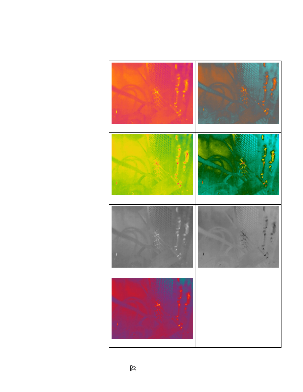
Achieving a good image11
Iron Arctic
Rainbow Rainbow high contrast
White hot Black hot
Lava
(Color) and push the navigation pad. This displays a submenu.
3. Use the navigation pad to select a different palette.
This table explains the different types of color palettes.
Follow this procedure:
1. Push the navigation pad to display the menu system.
2. Select
Find Quality Products Online at: sales@GlobalTestSupply.com
www.GlobalTestSupply.com

Achieving a good image11
for more
than 2 seconds.
Note You can also assign the function Calibrate to the programmable button. For more
information, see section 7.9 Programmable button.
4. Push the navigation pad to confirm and exit the menu mode.
11.6 Changing the measurement parameters
For accurate measurements, it is important to set the measurement parameters:
• Emissivity.
• Reflected temperature.
• Object distance.
• Atmospheric temperature.
• Relative humidity.
• External IR window compensation.
Emissivity is the most important measurement parameter to set correctly. If the Emissivity
is set to a low value, the Reflected temperature also becomes important. The parameters
Object distance, Atmospheric temperature, and Relative humidity are relevant for longer
distances. The External IR window compensation must be activated if a protective window or external lens is used.
You can set the measurement parameters globally. You can also change the Emissivity,
Reflected temperature, and Object distance parameters locally for a measurement tool.
For more information, see section 13.5 Changing the measurement parameters.
11.7 Performing a non-uniformity correction (NUC)
11.7.1 General
When the thermal camera displays Calibrating... it is performing what in thermography is
called a ”non-uniformity correction” (NUC). An NUC is an image correction carried out by
the camera software to compensate for different sensitivities of detector elements and
other optical and geometrical disturbances
calibration.
An NUC is performed automatically, for example at start-up, when changing a measurement range, or when the environment temperature changes.
You can also perform an NUC manually. This is useful when you have to perform a critical
measurement with as little image disturbance as possible. You may, for example, want to
perform a manual calibration just before you start recording a video sequence.
11.7.2 Performing an NUC manually
To perform a manual NUC, push and hold down the image archive button
5
. For more information, see section 27 About
11.8 Hiding all overlay
The camera overlay consists of overlay graphics and image overlay information. The
overlay graphics include items such as measurement tool symbols, result tables, and
status icons. The image overlay information, which you activate on the Settings menu,
provides additional information such as the date, emissivity, and atmospheric temperature. For more information, see section 6.4.5 Image overlay information.
5. Definition from the European standard EN 16714-3:2016, Non-destructive Testing—Thermographic Testing —
Part 3: Terms and Definitions.
Find Quality Products Online at: sales@GlobalTestSupply.com
www.GlobalTestSupply.com

Achieving a good image11
Image with camera overlay and image overlay
information.
Image with all overlay hidden.
You can choose to hide all camera overlay by pressing the programmable button.
Follow this procedure:
1. Push and hold the programmable button. This displays the Programmable button
menu.
2. Push the navigation pad up/down to select the function Hide image overlay graphics .
3. Push the navigation pad to confirm and exit the menu mode.
Find Quality Products Online at: sales@GlobalTestSupply.com
www.GlobalTestSupply.com

12
(Settings)
> Save options & storage > Digital camera = Off. When the digital camera is off, only
the image mode Thermal is enabled.
• The Thermal MSX, Thermal, and Picture in picture image modes only work correctly
for calibrated lenses. The lens that ships with the camera is factory calibrated. To calibrate a new lens, see section 7.16 Calibrating the lens–camera combination.
Working with image modes
12.1 General
The camera can capture both thermal and visual images at the same time. By choosing
the image mode, you select which type of image to display on the screen.
The camera supports the following image modes:
• Thermal: An infrared image is displayed.
• Thermal MSX (Multi Spectral Dynamic Imaging): The camera displays an infrared image where the edges of the objects are enhanced with visual image details.
• Picture in picture: An infrared image frame is displayed on top of the visual image.
• Digital camera: The visual image captured by the digital camera is displayed.
Note
• For the Thermal MSX, Thermal, and Picture in picture image modes, all thermal and
visual information is stored when an image is saved. This means that you can edit the
image later, in the image archive or in a FLIR Thermography software, and select any
of the image modes.
• For the Digital camera image mode, a digital image with full resolution (5 MP) is stored
when an image is saved. However, no thermal information is stored.
• You can choose to turn off the digital camera. This can, for example, be required in re-
stricted areas and in confidential (e.g., doctor/patient) situations. Select
12.2 Image examples
This table explains the different types of image modes.
Find Quality Products Online at: sales@GlobalTestSupply.com
www.GlobalTestSupply.com
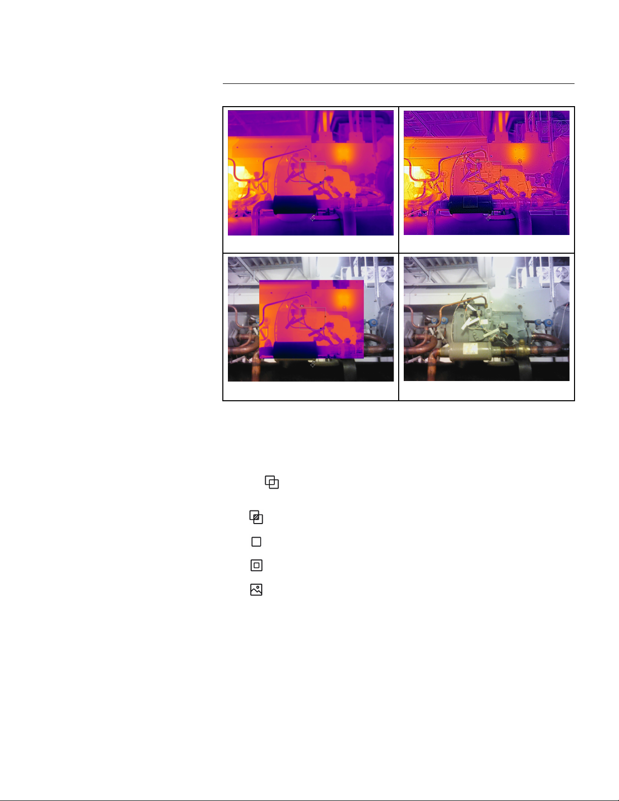
Working with image modes12
Thermal
Thermal MSX
Picture in picture
Digital camera
(Image mode) and push the navigation pad. This displays a submenu.
3. Use the navigation pad to select one of the following:
•
(Thermal MSX).
•
(Thermal).
•
(Picture in picture).
•
(Digital camera).
Note If the *.csq video format is selected (Settings > Save options & storage > Vid-
eo compression) and the recording mode Video is selected (Settings > Recording
mode), it will only be possible to select the image mode Thermal.
4. Push the navigation pad to confirm and exit the menu mode.
5. If Picture in picture mode is selected, you can at this point move and resize the infrared image frame. (For some camera models, the image frame is locked in the center
and cannot be moved.) Do the following:
5.1. To activate the Picture in picture tool, touch a corner of the infrared image
frame. The tool is now displayed showing five handles, one in the middle and
one in every corner of the frame.
5.2. To move the frame, touch and hold the middle handle and drag the frame.
5.3. To resize the frame, touch and hold one of the corner handles and drag the
corner of the frame.
12.3 Selecting an image mode
Follow this procedure:
1. Push the navigation pad to display the menu system.
2. Select
Find Quality Products Online at: sales@GlobalTestSupply.com
www.GlobalTestSupply.com
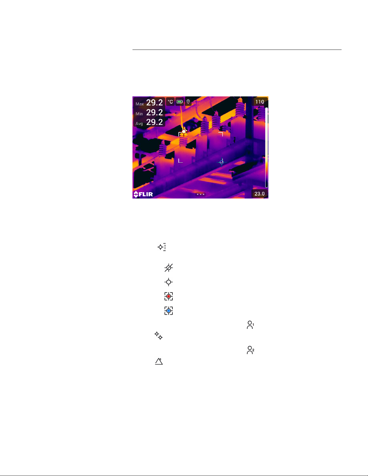
13
13.2 Adding/removing measurement tools
(Measurement) and push the navigation pad. This displays a submenu.
3. Use the navigation pad to select one of the following:
• Select
(No measurements) to remove all tools.
• Select
(Center spot) to add a center spot.
• Select
(Hot spot) to add a hot spot detection within a box area.
• Select
(Cold spot) to add a cold spot detection within a box area.
• Select (depending on the camera model)
(User preset 1) to add user preset 1
or
(3 spots) to add three spots.
• Select (depending on the camera model)
(User preset 2) to add user preset 2
or
(Hot spot - Spot) to add a hot spot and a spot and display the temperature
difference.
4. Push the navigation pad to confirm and exit the menu mode.
Working with measurement tools
13.1 General
To measure a temperature, you can use one or more measurement tools, e.g., a spotmeter or a box.
Follow this procedure:
1. Push the navigation pad to display the menu system.
2. Select
13.3 Editing user presets
Note The availability of this feature is dependent on the camera model.
A user preset is a measurement tool, or a group of measurement tools, with predefined
characteristics.
Follow this procedure:
1. Push the navigation pad to display the menu system.
Find Quality Products Online at: sales@GlobalTestSupply.com
www.GlobalTestSupply.com

Working with measurement tools13
(Measurement) and push the navigation pad. This displays a submenu.
3. Use the navigation pad to select
(User preset 1) or (User preset 2).
4. Push and hold the center of the navigation pad. This displays the Edit user preset
menu.
5. Select
(Add measurement) and push the navigation pad. This displays a
submenu.
6. Use the navigation pad to select one of the following:
• Select
(Add spot) to add a spot.
• Select
(Add box) to add a box.
• Select
(Add circle) to add a circle.
• Select
(Add delta) to set up a differential calculation.
7. Push the navigation pad. This displays the measurement tool on the screen.
8. Push the navigation pad. This displays a context menu, where you can select one or
more of the following actions (depending on the type of tool):
• Remove the tool.
• Resize, move, center, and rotate the tool.
• Set alarms.
• Display maximum, minimum, average, and area values.
• Set local parameters.
• When completed, select
(Done) and push the navigation pad.
9. When all measurement tools have been added, select
(Save as user preset).
10. Push the navigation pad to confirm and exit the menu mode.
(Move spot) and push the navigation pad.
3.2. Push the navigation pad up/down and left/right to move the spot.
4. To center the spot, select
Center spot and push the navigation pad.
5. When completed, push the navigation pad and select
(Done).
6. Push the navigation pad to confirm and exit the menu mode.
2. Select
13.4 Moving and resizing a measurement tool
13.4.1 General
You can move and resize a measurement tool.
Note When you select another measurement tool, any changes of position and size of
the current tool will be lost. If you wish to keep the position and size settings, use the user
preset feature, see section 13.3 Editing user presets.
13.4.2 Moving a spot
Note You can also move the spot by touching the screen.
Follow this procedure:
1. To select the spot, touch the tool on the screen. The tool is now displayed with a
frame.
2. Push the navigation pad—or touch and hold the tool. This displays a context menu.
3. To move the spot, do the following:
3.1. Select
Find Quality Products Online at: sales@GlobalTestSupply.com
www.GlobalTestSupply.com

Working with measurement tools13
(Move/resize) and push the navigation pad. This displays a submenu.
4. Use the navigation pad to select one of the following:
• Select
(Resize) to change the size of the tool.
• Select
(Move) to move the tool.
• Select
(Center box/circle) to center the tool.
5. Push the navigation pad up/down and left/right to resize or move the tool.
6. When completed, push the navigation pad and select
(Done).
7. Push the navigation pad to confirm and exit the menu mode.
(Settings) > Device settings > User inter-
face options > Emissivity mode > Select from materials table.
13.4.3 Moving and resizing a box or circle tool
Note You can also move and resize the measurement tool by touching the screen.
Follow this procedure:
1. To select the measurement tool, touch the tool on the screen. The tool is now displayed with one or more handles.
2. Push the navigation pad—or touch and hold the tool. This displays a context menu.
3. Select
13.5 Changing the measurement parameters
13.5.1 General
For accurate measurements, it is important to set the measurement parameters.
Note During normal operation there is typically no need to change the default measurement parameters, see section 13.5.3 Recommended values.
13.5.2 Types of parameters
The camera can use these measurement parameters:
• External IR window compensation, i.e., the temperature of any protective windows,
external lenses (e.g., the close-up lens), etc., that are set up between the camera and
the object of interest. If no protective window, protective shield, or external lens is
used, this value is irrelevant and should be left inactive.
• Object distance, i.e., the distance between the camera and the object of interest.
Note The camera can be configured to automatically measure the distance when
an image is saved. With this setting, the Object distance parameter in the image data
is automatically updated with the measured distance when an image is saved. (There
is no effect on the Object distance setting in live mode.) For more information, see
section 6.3 Laser distance meter and laser pointer.
• Atmospheric temperature, i.e., the temperature of the air between the camera and the
object of interest.
• Relative humidity, i.e., the relative humidity of the air between the camera and the ob-
ject of interest.
• Reflected temperature, which is used when compensating for the radiation from the
surroundings reflected by the object into the camera. This property of the object is
called “reflectivity.”
• Emissivity, i.e., how much radiation an object emits, compared with the radiation of a
theoretical reference object at the same temperature (called a “blackbody”). The opposite of emissivity is reflectivity. The emissivity determines how much of the radiation
originates from the object as opposed to being reflected by it.
Note There is an Emissivity mode setting, which you can use to enter the emissivity
by material instead of by value. Select
Find Quality Products Online at: sales@GlobalTestSupply.com
www.GlobalTestSupply.com

Working with measurement tools13
(Measurement parameters) and push the navigation pad. This displays a
submenu.
3. Use the navigation pad to select one or more of the global measurement parameters:
•
(External IR window compensation).
•
(Object distance).
•
(Atmospheric temperature).
•
(Relative humidity).
•
(Reflected temperature).
•
(Emissivity).
4. Push the navigation pad to display a dialog box.
5. Use the navigation pad to change the parameter.
6. Push the navigation pad to confirm and exit the menu mode.
13.5.4.2 Changing local parameters
You can change the local parameters for a measurement tool.
A P next to the measurement tool on the screen indicates that local parameters have
been activated for the tool.
Emissivity is the most important measurement parameter to set correctly. If the Emissivity
is set to a low value, the Reflected temperature also becomes important. The parameters
Object distance, Atmospheric temperature, and Relative humidity are relevant for longer
distances. The External IR window compensation must be activated if a protective window or external lens is used.
13.5.3 Recommended values
If you are unsure about the values, the following are recommended:
Object distance 1.0 m (3.3 ft.)
Atmospheric temperature
Relative humidity 50%
Reflected temperature 20°C (69°F)
Emissivity 0.95
20°C (69°F)
13.5.4 Procedure
You can set the measurement parameters globally. You can also change the Emissivity,
Reflected temperature, and Object distance parameters locally for a measurement tool.
Local parameters are normally only effective for a fixed setup, where each measurement
tool is set for a specific object of interest. For a general handheld application, the global
parameters are usually sufficient.
Note Emissivity and Reflected temperature are the two most important measurement
parameters to set correctly in the camera.
13.5.4.1 Setting global parameters
Follow this procedure:
1. Push the navigation pad to display the menu system.
2. Select
Find Quality Products Online at: sales@GlobalTestSupply.com
www.GlobalTestSupply.com

Working with measurement tools13
(Use local parameters) and push the navigation pad.
4. Push the navigation pad to activate the use of local parameters. This displays a
submenu.
5. Use the navigation pad to select one or more of the local measurement parameters.
6. Push the navigation pad to display a dialog box.
7. Use the navigation pad to change the parameter.
8. Push the navigation pad. This closes the dialog box.
9. When completed, push the navigation pad and select
(Done).
10. Push the navigation pad to confirm and exit the menu mode.
Note When you select another measurement tool, the local parameters are reset. If
you wish to keep the local parameter settings, use the user preset feature, see section
13.3 Editing user presets.
(Max/Min/Avg).
4. Push the navigation pad. This displays a submenu.
5. Use the navigation pad to select one or more of the following:
• Select
(Max) to display the maximum value.
• Select
(Min) to display the minimum value.
• Select
(Avg) to display the average value.
• Select (depending on the tool)
or (Area) to display the area of an object
within the measurement tool
(Max & min markers) to display the maximum and minimum markers
(the hot/cold spots).
6. Push the navigation pad to toggle the function between inactive and active.
7. When completed, push the navigation pad down to close the submenu.
8. Select
(Done) and push the navigation pad.
Follow this procedure:
1. To select the measurement tool, touch the tool on the screen. The tool is now displayed with one or more handles.
2. Push the navigation pad—or touch and hold the tool. This displays a context menu.
3. Select
13.6 Displaying values in the result table
For the box and circle tools, you can set the camera to display the maximum, minimum,
average, and area values in the result table.
Follow this procedure:
1. To select the measurement tool, touch the tool on the screen. The tool is now displayed with one or more handles.
2. Push the navigation pad—or touch and hold the tool. This displays a context menu.
3. Use the navigation pad to select
abled (Settings > Device settings > Lamp & laser > Enable lamp & laser). For more
information, see section 7.6 Measuring areas.
• Select
6. The availability of this feature is dependent on the camera model.
6
. Area measurements require that the laser is en-
Find Quality Products Online at: sales@GlobalTestSupply.com
www.GlobalTestSupply.com

Working with measurement tools13
(Add measurement) and then select
(Add delta).
• If you are editing an image in the archive, select
(Measurement) and then se-
lect
(Add delta).
2. Push the navigation pad. This displays a dialog box where you can select the measurement tools that you want to use in the difference calculation. You can also select a
fixed-temperature reference.
3. Push the navigation pad. The result of the difference calculation is now displayed on
the screen.
is displayed in the result table.
When an alarm is triggered, the value in the result table is displayed in red (above alarm)
or blue (below alarm) and the symbol
(above alarm) or (below alarm) is blinking.
You can also set an audible alarm (there will be a “beep” when the alarm is triggered).
13.8.4 Procedure
There are different procedures for setting up an alarm for a spot, for a box or circle, and
for a difference calculation.
13.7 Creating and setting up a difference calculation
A difference calculation gives the difference between the values of two known measurement results.
Note
• You can set up a difference calculation when previewing an image or when editing an
image in the archive.
• Depending on the camera model, you can also set up a difference calculation when
defining user presets or by selecting the measurement tool Hot spot - Spot.
• This procedure assumes that you have previously laid out at least one measurement
tool on the screen.
Follow this procedure:
1. To set up a difference calculation, do the following:
• If you are defining user presets, select
13.8 Setting a measurement alarm
13.8.1 General
You can make the camera trigger an alarm when certain measurement conditions are
met.
13.8.2 Types of alarm
You can choose between the following alarm types:
• Above: Triggers an alarm when the temperature is above the preset alarm
temperature.
• Below: Triggers an alarm when the temperature is below the preset alarm
temperature.
13.8.3 Alarm signals
When an alarm is set, the symbol
Find Quality Products Online at: sales@GlobalTestSupply.com
www.GlobalTestSupply.com

Working with measurement tools13
(Set alarm on spot) and push the navigation pad. This displays a dialog
box.
4. In the dialog box, you can define the settings for the alarm.
• Alarm condition: The condition that triggers the alarm. Applicable values are
Above, Below, or Off.
• Alarm limit: The temperature value that will be the critical condition when an alarm
is triggered or not.
• Alarm sound: Applicable values are Beep or No sound.
5. Push the navigation pad. This closes the dialog box.
13.8.4.2 Setting up an alarm for a box or circle
Note This procedure assumes that you have previously set the camera to display at
least one value (maximum, minimum, or average) in the result table. For more information, see section 13.6 Displaying values in the result table.
Follow this procedure:
1. To select the measurement tool, touch the tool on the screen. The tool is now displayed with one or more handles.
2. Push the navigation pad—or touch and hold the tool. This displays a context menu.
3. Select
(Set alarm) and push the navigation pad. This displays a dialog box.
4. In the dialog box, you can define the settings for the alarm.
• Alarm condition: The condition that triggers the alarm. Applicable values are
Above, Below, or Off.
• Select measurement: Applicable settings are the values you have previously de-
fined (Max, Min, and/or Avg).
• Alarm limit: The temperature value that will be the critical condition when an alarm
is triggered or not.
• Alarm sound: Applicable values are Beep or No sound.
5. Push the navigation pad. This closes the dialog box.
13.8.4.3 Setting up an alarm for a difference calculation
Note
• You can set up an alarm for a difference calculation when defining user presets (de-
pending on the camera model), or when editing an image in the archive.
• This procedure assumes that you have previously set up a difference calculation.
To set up an alarm for a difference calculation, do the following:
1. If you are editing an image in the archive, select
(Measurement).
2. Select
(Select) and push the navigation pad. This displays a dialog box.
3. Select Delta and push the navigation pad. This displays a context menu.
4. Select
(Set alarm on delta) and push the navigation pad. This displays a dialog
box.
13.8.4.1 Setting up an alarm for a spot
Follow this procedure:
1. To select the spot, touch the tool on the screen. The tool is now displayed with a
frame.
2. Push the navigation pad—or touch and hold the tool. This displays a context menu.
3. Select
Find Quality Products Online at: sales@GlobalTestSupply.com
www.GlobalTestSupply.com

Working with measurement tools13
5. In the dialog box, you can define the settings for the alarm.
• Alarm condition: The condition that triggers the alarm. Applicable values are
Above, Below, or Off.
• Alarm limit: The temperature value that will be the critical condition when an alarm
is triggered or not.
• Alarm sound: Applicable values are Beep or No sound.
6. Push the navigation pad. This closes the dialog box.
Find Quality Products Online at: sales@GlobalTestSupply.com
www.GlobalTestSupply.com

14
Above alarm
Below alarm
Interval alarm
Condensation alarm
Insulation alarm
Working with color alarms and isotherms
14.1 Color alarms
By using color alarms (isotherms), anomalies can easily be discovered in an infrared image. The isotherm command applies a contrasting color to all pixels with a temperature
above, below, or between the set temperature levels. The camera also features isotherm
types that are specific to the building trade: condensation and insulation alarms.
You can make the camera trigger the following types of color alarms:
• Above alarm: This will apply a contrasting color to all pixels with a temperature above
the specified temperature level.
• Below alarm: This will apply a contrasting color to all pixels with a temperature below
the specified temperature level.
• Interval alarm: This will apply a contrasting color to all pixels with a temperature be-
tween two specified temperature levels.
• Condensation alarm: Triggers when the camera detects a surface where the relative
humidity exceeds a preset value.
• Insulation alarm: Triggers when there is an insulation deficiency in a wall.
This table explains the different color alarms (isotherms).
Find Quality Products Online at: sales@GlobalTestSupply.com
www.GlobalTestSupply.com

Working with color alarms and isotherms14
(Color) and push the navigation pad. This displays a submenu.
3. Use the navigation pad to select one of the following:
•
(Above alarm).
•
(Below alarm).
•
(Interval alarm).
4. Push the navigation pad. This displays a dialog box where you can define the settings
for the alarm.
For the Above alarm and Below alarm, the following parameters can be set:
• Temperature limit.
• Palette.
For the Interval alarm, the following parameters can be set:
• Low temperature.
• High temperature.
• Palette.
5. Push the navigation pad. This closes the dialog box.
14.1.2 Building isotherms
Note The Condensation and Insulation alarms are not supported by all camera models.
14.1.2.1 About the Condensation alarm
To detect areas with potential moisture problems, you can use the Condensation alarm.
You can set the relative humidity above which the isotherm will colorize the image.
14.1.2.2 About the Insulation alarm
The Insulation alarm can detect areas where there may be an insulation deficiency in the
building. It will trigger when the insulation level (which is called the thermal index in the
camera) falls below a preset value of the energy leakage through a wall.
Different building codes recommend different values for the insulation level, but typical
values are 60–80% for new buildings. Refer to your national building code for
recommendations.
14.1.2.3 Setting up condensation and insulation alarms
1. Push the navigation pad to display the menu system.
2. Select
(Color) and push the navigation pad. This displays a submenu.
3. Use the navigation pad to select one of the following:
•
(Condensation alarm).
•
(Insulation alarm).
14.1.1 Setting up above, below, and interval alarms
1. Push the navigation pad to display the menu system.
2. Select
Find Quality Products Online at: sales@GlobalTestSupply.com
www.GlobalTestSupply.com

Working with color alarms and isotherms14
4. Push the navigation pad. This displays a dialog box where you can define the settings
for the alarm.
For the Condensation alarm, the following parameters can be set:
• Atmospheric temperature: The current atmospheric temperature.
• Relative humidity: The current relative humidity.
• Relative humidity limit: The relative humidity level at which you want the alarm to
be triggered. A relative humidity of 100% means that water vapor condenses from
the air as liquid water (= dewpoint). A relative humidity of about 70% or above can
cause mold.
For the Insulation alarm, the following parameters can be set:
• Indoor temperature: The current indoor temperature.
• Outdoor temperature: The current outdoor temperature.
• Thermal index: The insulation level (an integer between 0 and 100).
5. Push the navigation pad. This closes the dialog box.
Find Quality Products Online at: sales@GlobalTestSupply.com
www.GlobalTestSupply.com

15
(Settings) > Save options & storage > Add annotation after saving.
• You can also add annotations to a saved image in the image archive.
Note This section describes the procedures for adding annotations to a saved image
in the image archive. Adding annotations when saving an image works in a similar way.
icon and push the navigation pad.
4. On the right toolbar, select the
icon and push the navigation pad.
5. A soft keyboard is displayed, where you can enter text by touching the screen.
6. When completed, touch Done on the soft keyboard.
icon and push the navigation pad.
4. On the right toolbar, select the
icon and push the navigation pad. This displays a
table.
5. (Optional step.) On the top toolbar, do one of the following:
• To clear the content of the current table, select the
icon and push the naviga-
tion pad.
• To select another table template, select the
icon and push the navigation pad.
Annotating images
15.1 General
You can save additional information with an infrared image by using annotations. Annotations make reporting and post-processing more efficient by providing essential information about the image, e.g., conditions and information about where an image is taken.
Annotations are added to the image file and can be viewed and edited in the camera or
in a FLIR Thermography software.
• You can set the camera to display annotation tools when an image is saved. Select
15.2 Adding a note
You can add a text note to the image file. Using this feature, you can annotate images by
entering free-form text.
Follow this procedure:
1. Open the image in the image archive.
2. Push the navigation pad to display the top toolbar.
3. On the top toolbar, select the
15.3 Adding a text comment table
You can save a table with textual information to the image file. This feature is a very efficient way of recording information when you are inspecting a large number of similar objects. The idea behind using a table with textual information is to avoid filling out forms or
inspection protocols manually.
The camera ships with an example text comment table template. You can also create
your own templates. For more information, see section 15.3.1 Creating a text comment
table template.
Follow this procedure:
1. Open the image in the image archive.
2. Push the navigation pad to display the top toolbar.
3. On the top toolbar, select the
Find Quality Products Online at: sales@GlobalTestSupply.com
www.GlobalTestSupply.com

Annotating images15
icon
and enter other text by touching the screen.
Note Text entered by the keyboard will be saved to the text comment table tem-
plate. Next time you add a text comment table annotation, the entered text will be
displayed as a predefined value.
7. When completed, select Save & Exit at the bottom of the table. Push the navigation
pad to confirm.
15.3.1 Creating a text comment table template
You can create a text comment file manually. You can also create a text comment file using a FLIR Thermography software.
15.3.1.1 Manually creating a table template
A text comment file (*.tcf) is an annotation format that is proprietary to FLIR Systems. It
defines a table structure that can be used to add text table annotations to FLIR images.
You can create text comment files (*.tcf files) and use these files as table templates in
the camera.
The camera ships with an example text comment table file: example_text_comment.tcf.
The file is stored on the memory card in the subfolder \TextTableTemplates. You can
make a copy of the example file and modify it using a text editor such as Microsoft
Notepad.
When creating or modifying a text comment file, keep the following rules in mind:
1. Lines starting with “#” are regarded as comments and will be ignored.
2. Lines that start with “<” and end with “>” are labels and will appear on the left-hand
side of the table.
3. Non-empty lines under a label line are regarded as values and will be displayed as
options to the label above.
4. When you save the file, select UTF-8 encoding. With UTF-8 encoding, the file will
support all languages currently supported by the camera.
5. The template will be updated by the camera if you add or remove values in the text table annotations dialog in the camera. This enables you to modify its content while
you are working with the camera.
6. The camera will find all text table template files if:
• They are placed on the memory card in the subfolder \TextTableTemplates.
• They have an ASCII filename and the file extension .tcf. (ASCII characters include
a–z, A–Z, 0–9, and basic punctuation, and spaces can be used. The file can contain non-ASCII text, but the filename must be ASCII.)
15.3.1.1.1 Example mark-up structure
The file format for the text comment table template is *.tcf. This code sample is an example mark-up structure of such a file, and shows how the mark-up appears in a text editor
such as Notepad.
<Site>
Company A
Company B
<Location>
Substation A
<Object>
Engine
Vent
6. For each row in the table, do the following:
• Push the navigation pad. This displays the predefined values.
• Push the navigation pad up/down to select a predefined value. Push the navigation pad to confirm.
• Instead of selecting a predefined value, you can select the keyboard
Find Quality Products Online at: sales@GlobalTestSupply.com
www.GlobalTestSupply.com

Annotating images15
icon and push the navigation pad.
4. On the right toolbar, select the
icon and push the navigation pad.
5. A context menu is displayed.
6. To start a recording, select
(Record) and push the navigation pad.
7. To stop the recording, select
(Stop) and push the navigation pad.
8. To listen to the recording, select
(Play) and push the navigation pad.
9. To delete the recording, select
(Delete) and push the navigation pad.
10. When completed, select
(Done) and push the navigation pad.
icon and push the navigation pad.
4. On the right toolbar, select the
icon and push the navigation pad.
5. You are now in sketch mode. Draw the sketch by touching the screen.
Vault
Door
<ObjectID>
A1a1
A1b2
A1c3
<Deviation>
Overload
Moisture
Draft
<Remedy>
Replace
Fix
No action
<Severity>
Critical
Non-critical
<Severity>
15.4 Adding a voice annotation
A voice annotation is an audio recording that is saved to the infrared image file. The recording can be played back in the camera, and in image analysis and reporting software
from FLIR Systems.
The voice annotation is recorded using the built-in microphone. You can also use a Bluetooth-enabled headset. For information on how to pair a headset with the camera, see
section 21 Pairing Bluetooth devices.
Follow this procedure:
1. Open the image in the image archive.
2. Push the navigation pad to display the top toolbar.
3. On the top toolbar, select the
15.5 Adding a sketch
You can add a freehand drawing to an infrared image.
Follow this procedure:
1. Open the image in the image archive.
2. Push the navigation pad to display the top toolbar.
3. On the top toolbar, select the
Find Quality Products Online at: sales@GlobalTestSupply.com
www.GlobalTestSupply.com

Annotating images15
(Draw) and push the navigation
pad. Select the color and push the navigation pad.
• To erase, select
(Eraser) and push the navigation pad. Erase parts of the
sketch by touching the screen.
• To add an arrow, circle, or cross, select
(Stamp sketch) and push the navigation pad. Select the type of stamp and push the navigation pad. The stamp is displayed in the center of the screen. You can move the stamp by using the
navigation pad or by touching the screen. When completed, push the navigation
pad.
• To clear, select
(Clear all) and push the navigation pad.
• When the sketch is completed, select
(Save) and push the navigation pad.
6. (Optional step.) Push the navigation pad. This displays a context menu. Do one or
more of the following:
• To change the color of the sketch tools, select
Find Quality Products Online at: sales@GlobalTestSupply.com
www.GlobalTestSupply.com
 Loading...