

FLIR Security DGR201 Installation Manual

SAFETY PRECAUTIONS
All the following safety and operated instructions which will prevent harm or damage to the operator
and other persons should be read before the unit is operated.
WARNING
To reduce the risk of fire or electric shock, do not expose this appliance to rain or moisture.
Do not block ventilation openings.
Do not place anything on top of the unit that might spill or fall into it.
Do not attempt to service this unit yourself as opening or removing covers may expose you
to dangerous voltage or other hazards. Please refer all servicing to qualified service
personnel.
Do not use liquid cleaners or aerosols for cleaning.
This installation should be by a qualified service person and should conform to all local
codes.
To prevent fire or electric shock, do not overload wall outlets or extension cord.
This unit must be grounded to reduce the risk of electric shock hazard.
CAUTION
Danger of explosion if the Lithium battery (RTC Battery) is incorrectly replaced.
Danger of explosion if battery is incorrectly replaced. Replace only with the same or
equivalent type recommended by the manufacturer. Dispose of used batteries
according to the manufacturer’s instructions.
Risk of explosion if replaced by an incorrect type. Dispose of used batteries according to
the instructions.
INFORMATION
This equipment has been tested and found to comply with the limits for a Class A digital device,
pursuant to Part 15 of the FCC Rules. These limits are designed to provide reasonable
protection against harmful interference when the equipment is operated in a commercial
environment. This equipment generates, uses, and can radiate radio frequency energy and, if
not installed and used in accordance with the instruction manual, may cause harmful
interference to radio communications.
Operation of this equipment in a residential area is likely to cause harmful interference in which
case the user will be required to correct the interference at his own expense.

Table of Contents
1. PRODUCT FEATURES .................................................................................................... 4
1.1 Product Introduction ..................................................................................................................4
1.2 Product Features........................................................................................................................4
2. DESCRIPTION OF THE FRONT/REAR VIEW ................................................................ 5
2.1 Front View..................................................................................................................................5
2.2 Rear View ................................................................................................................................... 8
2.3 ALARM In/Out ...........................................................................................................................9
3. INSTALLATION.............................................................................................................. 10
3.1 Basic Connection .....................................................................................................................10
3.2 Hard-Disk Drive Installation................................................................................................... 13
3.3 System Information ..................................................................................................................14
3.4 Updating System Software ....................................................................................................... 15
4. BASIC OPERATIONS .................................................................................................... 16
4.1 Configuring Recording Settings...............................................................................................16
4.2 Recording Operations..............................................................................................................19
4.3 Playback Viewing Options .......................................................................................................23
4.4 Search Operations....................................................................................................................25
4.5 Data Backup............................................................................................................................. 28
4.6 Key Lock Operation ................................................................................................................. 31
5. MENU SETUP ................................................................................................................ 32
5.1 RECORD Option page............................................................................................................. 32
5.2 ALARM SETTING ....................................................................................................................33
5.3 CLOCK / TIMER......................................................................................................................36
5.4 COMMUNICATION ................................................................................................................37
5.5 DISK SETTING........................................................................................................................40
5.6 SYSTEM ...................................................................................................................................41
2

Table of Contents (cont)
6. RS-232 & RS-485 PROTOCOL ..................................................................................... 44
6.1 Setup.........................................................................................................................................44
6.2 Communication Protocol .........................................................................................................44
7. IDE HARD DISK INSTALLATION.................................................................................. 48
7.1 Built-in hard disk .....................................................................................................................48
7.2 Mobile Rack .............................................................................................................................49
8. SYSTEM DEFAULT........................................................................................................ 52
9. O.S.D MESSAGE ........................................................................................................... 54
10. NETWORK VIEWER AND IMAGE VIEWER ............................................................... 55
10.1 The Network Viewer............................................................................................................... 55
10.2 The Image Viewer...................................................................................................................63
11. INDEX TABLE .............................................................................................................. 64
12. NETWORK CONFIGURATION.................................................................................... 65
12.1 Cable Connections .................................................................................................................65
12.2 Configure Your DGR201 Network Settings............................................................................66
12.3 TCP/IP Communication Software.......................................................................................... 68
12.4 TCP/IP installation ................................................................................................................70
12.5 TCP/IP Configuration setting ................................................................................................70
12.6 Connection Testing.................................................................................................................71
13. SPECIFICATIONS........................................................................................................ 73
14. COMPATIBLE MULTIPLEXER DRIVES...................................................................... 74
15. LIMITED WARRANTY.................................................................................................. 75
3

1. PRODUCT FEATURES
1.1 Product Introduction
The DGR201 is a networkable, multiplexer compatible single channel Digital Video Recorder with
remote viewing and control software. It’s comprehensive range of features makes it ideally suited for a
number of applications, providing a superior solution for video surveillance applications.
1.2 Product Features
* Stores video digitally on hard-disk drives instead of VCR tapes.
* Large Capacity, 2 hard-disk drive capability provides extended recording. (One removable)
* Hard-disk drive hot-swapping capability.
* Pre-alarm image recording.
* Multiplexer compatible.
* Time-lapse and real-time recording.
* Refresh rate up to 60 IPS (50 IPS for PAL).
* Image quality selectable at 4 different levels for recording.
* Event/Timer/Alarm recording mode.
* Quick search by time, alarm, event, and recording list.
* Fast and slow playback of recorded video at various speeds.
* Single-picture playback.
* On-screen setup menu, title and system timer.
* Password protection.
* Video Motion detection.
* Disk-full warning and operation status LEDs.
* RS-232, RS-485 communication port.
* Remote control via RS-232, RS-485 and Ethernet ports
* Power interruption recovery.
* Operation-status record log.
* Distributing live and recorded images through TCP/IP network environment.
* Audio function included
* Built-in SD card slot for copying image to SD card
* Support DHCP protocol.
4
2. DESCRIPTION OF THE FRONT/REAR VIEW
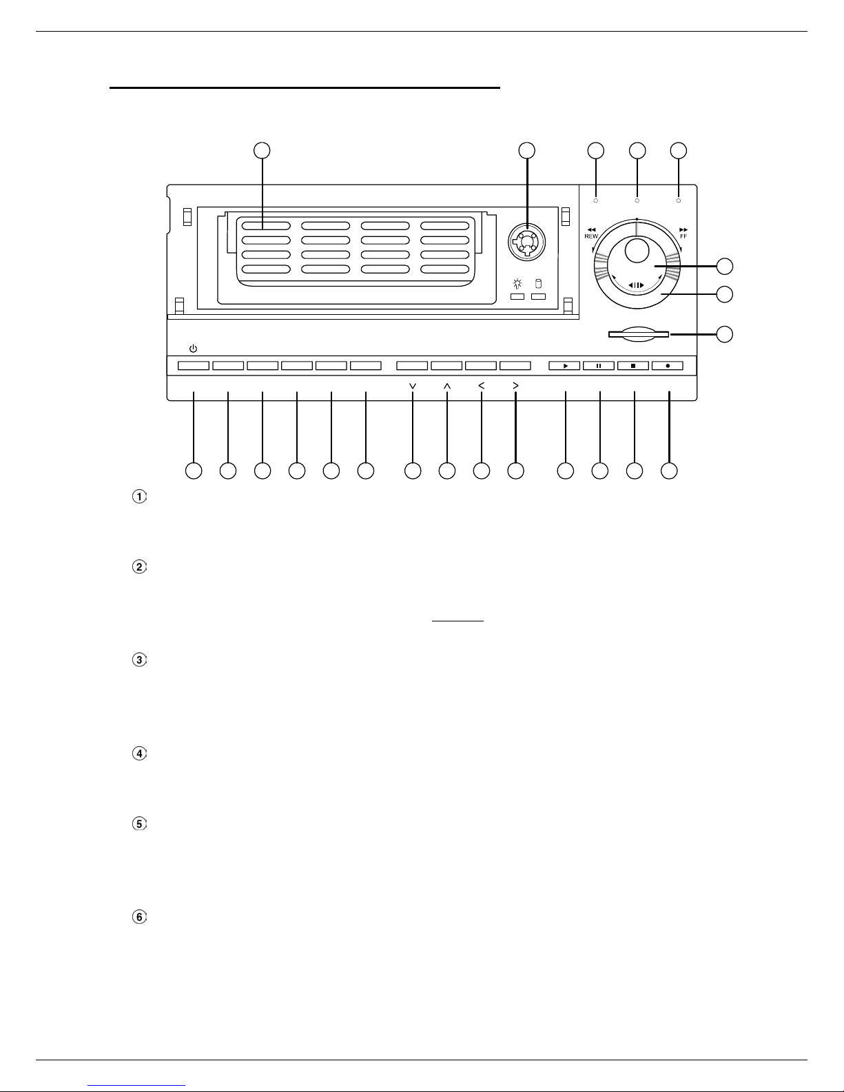
2.1 Front View
1 2
Power
7
Removable Hard Disk drive compartment:
Monitor
16
Display
8
Setup
Search
10 11 1413 12
Enter
9
15
This compartment houses the external removable hard disk drive.
NOTE: The compartment must be locked before the hard drive can be used.
19
SD Card
Play4Pause3Stop
18
A-rec T-recDISK
5
17
20
21
22
Rec
6
Hard Disk compartment lock:
The key lock secures the hard disk in place.
NOTE: The Hard Disk compartment must be unlocked
to remove the hard disk from the hard disk
compartment.
PAU SE button:
Press the PAUSE button to pause the video during playback. Pressing the PAUSE button while in
the PAUSE MODE will advance the video by one frame.
The green “PAUSE” LED will be illuminated.
PLAY button:
Press the PLAY button to play recorded video from the hard disk.
The green LED under the “PLAY” button will be illuminated
STOP button:
Press the STOP button to stop the playing of video during playback, or stop recording during a
manual record.
The green LED under the “STOP” button will be illuminated
REC button:
Press the REC button to start manually recording video onto the hard disk while viewing live video
display mode.
The red LED under the REC button will be illuminated.
5

POWER button:
Press and hold POWER button to turn on the unit, press (and hold again) to turn the unit off.
DISPLAY button:
Press to show the system operation status on the screen.
SETUP button:
Press the SETUP button to enter the main setup menu.
Press again to exit the setup menu.
SEARCH button:
Press the SEARCH to enter the search mode to access recorded video.
< (Left) / > (Right) buttons:
Press the two buttons to highlight desired items in the menu setup mode.
To activate the Key Lock feature, press and hold the < > buttons simultaneously.
To deactivate the Key Lock feature after it has been activated, press the < > buttons
simultaneously.
Up / Down buttons:
Press these two buttons to select the desired contents for programming in the setup menu mode.
ENTER Button:
Press the ENTER button to select or enter an item while in the setup menu.
When changing a value within the setup menu, press the ENTER to save the change.
MONITOR button:
Press the MONITOR button to toggle between multiplexer-decoded video and the encoded video
to be displayed when connected with a multiplexer.
When the MONITOR button LED is illuminated, the unit is displaying decoded video (The images
are not multiplexing.) While in this mode, the DGR201 will not display the OSD message of the
unit on the screen although the OSD message is being recorded onto the hard-disk drives.
When the MONITOR button LED is off, the unit is displaying encoded video. (The images switch
swiftly).
T-rec Indicator:
The T-rec LED turns on when recording has been triggered by a timer (schedule).
A-REC Indicator:
The A-rec LED turns on when recording has been triggered by an external alarm.
DISK Status Indicator:
The indicator shows the operation status of the unit’s hard-disk drives.
When the LED is green, the Hard-Disk is The green light indicates the hard-disk drive is storing or
retrieving data. The red light signals the hard-disk drive is filling up. The orange light indicates the
hard-disk is retrieving at disk-full status.
Shuttle Ring:
The shuttle ring is used to playback video at different speeds in forward or reverse. Turning the
shuttle ring to the left will play recorded video in reverse, turning the shuttle ring to the right will
play the video at different speeds in the forward direction.
6

Jog Dial:
The Jog Dial can be used to step frame by frame in the forward or reverse direction.
SD CARD Slot:
The SD Card Slot has two purposes, 1) to upgrade the internal system software and 2) to archive
critical video data.
7
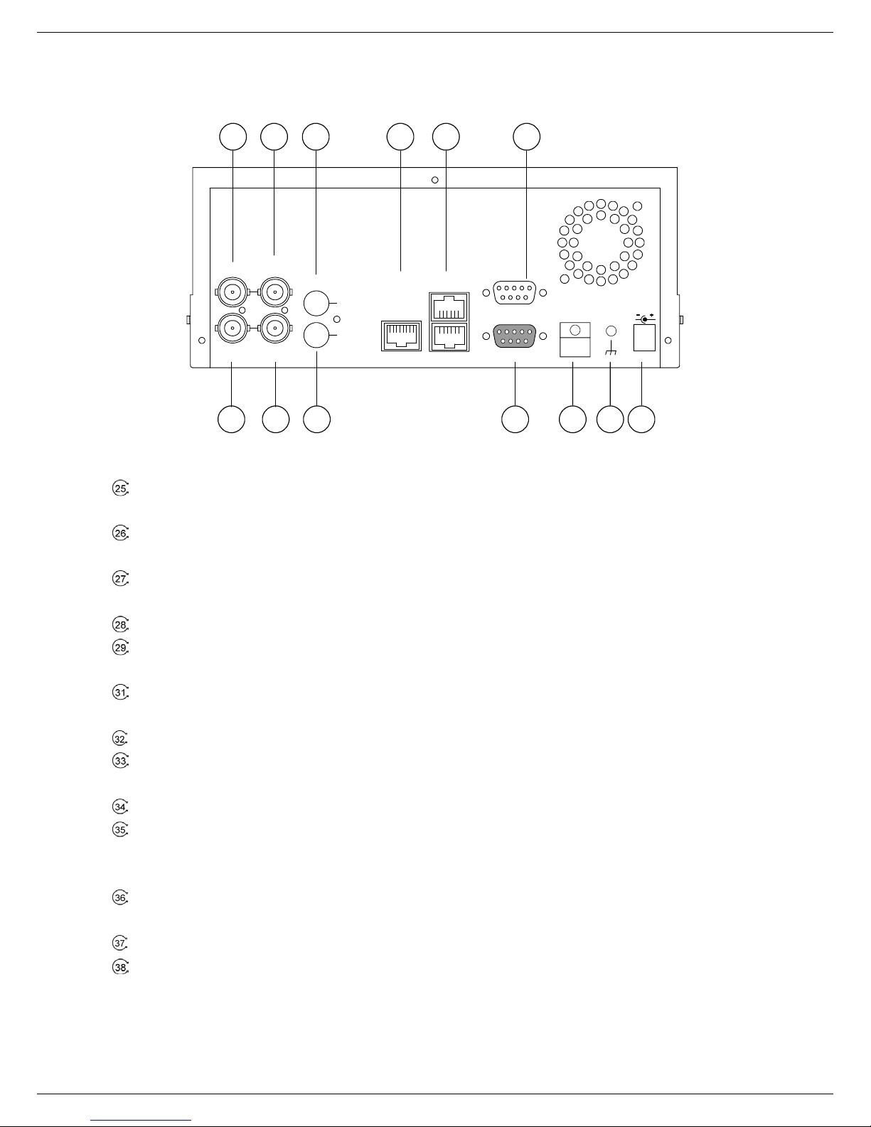
2.2 Rear View
25 26 27 28 29 31
VIDEO
TO
MUX'S VCR IN
FROM MUX
MAIN MONITOR
IN
OUT
TO
MONITOR
AUDIO
OUT
RS-485
IN
ETHERNET
10/100
RS-232
ALARM
I/O
DC12V
32 33
34 35 37 38 36
VIDEO IN Connector: This BNC connector is used to connect the video output from a camera or a
MUX to the DGR201.
FROM MUX MAIN MONITOR Connector: This BNC connector is used to connect the live video output
from a MUX to the DGR201.
AUDIO IN Connector: This connector is used to connect the audio output from a camera, a MUX or
other devices to the DGR201.
ETHERNET 10/100 Connector: This is a standard RJ-45 connector for 10/100 Mbps Ethernet networks.
RS-485 Port: The RS-485 communication port allows two or more units to be serially connected to
expand the storage capacity.
RS-232 Port: The RS-232 communication port functions as a connector to an external control device.
Please refer to RS-232 & RS-485 Protocol for more details.
VIDEO OUT Connector: This connector provides the unit’s composite video signals to a MUX.
MONITOR Connector: This connector provides the unit’s composite video or a MUX’s live signal if
connected to a display device.
AUDIO OUT: This provides the unit’s audio signal to a speaker.
ALARM I/O: This is a 9-PIN D-SUB connector including SWITCH OUT, GROUND, ALARM OUT, DISK
FULL, RECORD IN, ALARM RESET, and ALARM IN for connecting with external devices. Please
refer to the section 2.3 for details.
Plug Inlet: The inlet connects to an external power supply. Connect 12 V DC UL Listed Class 2 Power
Supply.
AC Wire Strain Relief: The wire strain relief secures the power cord and keeps it in place.
Ground Screw’s: The ground screw is for chassis terminal.
8
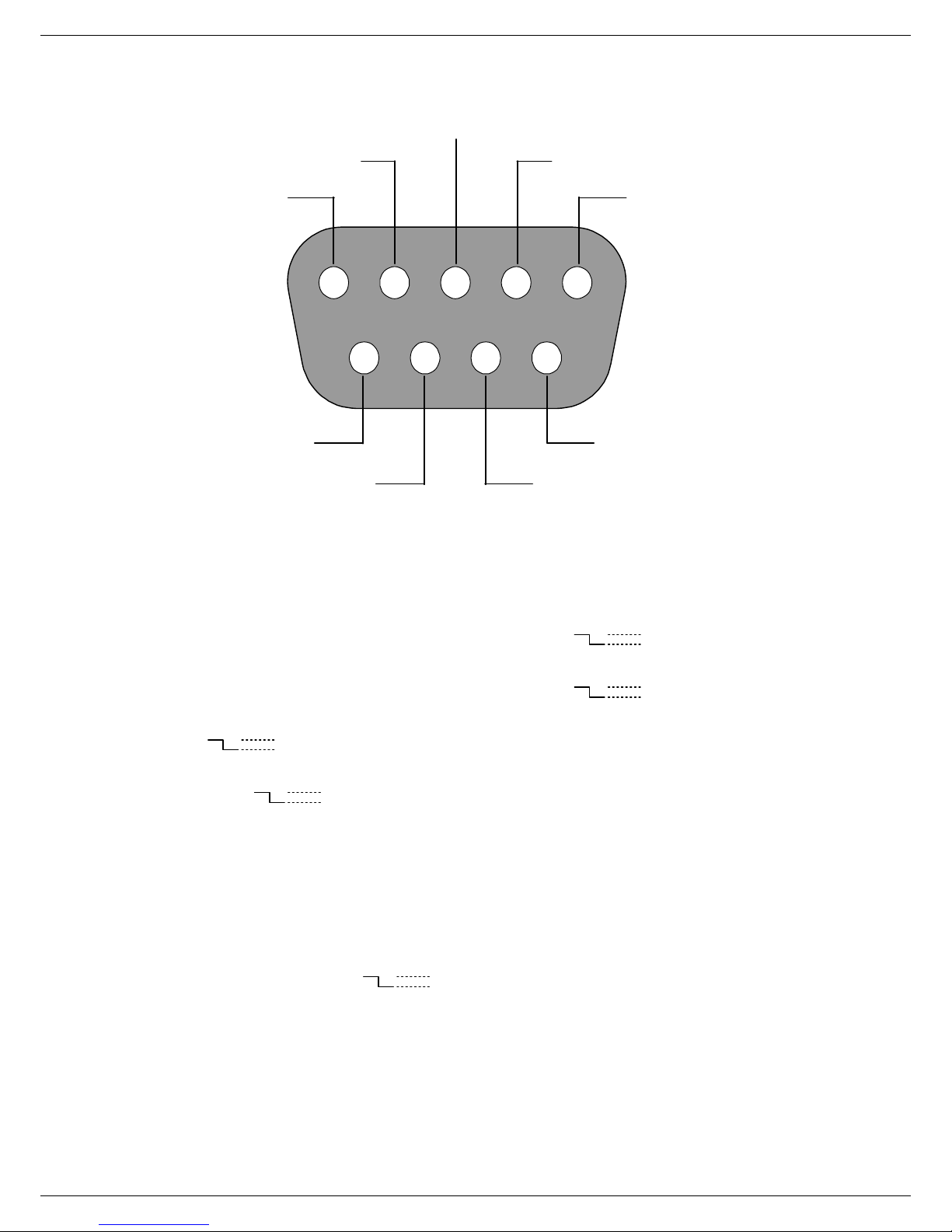
2.3 ALARM In/Out
DISK FULL
ALARM RESET
ALARM OUT
RECORD IN GROUND
12345
6789
ALARM IN
NO CONNECTION NO CONNECTION
1. GND: Ground Contact.
2. ALARM OUT (OUTPUT): This output is triggered by an alarm condition and is typically
connected to external devices such as buzzers or lights. (
3. DISK FULL (OUTPUT): This output is triggered when the Hard Disk is full and is typically
connected to external devices such as buzzers or lights. (
4. ALARM RESET (INPUT): When this pin is activated, an alarm condition will be cleared.
5V
0V(Active)
(
5. RECORD (INPUT): When this PIN is activated, the unit will start recording for the duration it is
active. (
6. SWITCH OUT (MUX SYNC OUTPUT): This pin sends out timing signals (falling / negative) to a
multiplexer’s trigger terminal to synchronize the multiplexer with the DGR201 .
)
5V
0V(Active)
)
SWITCH OUT
5V
0V(Active)
)
5V
0V(Active)
)
7. NO CONNECTION
8. NO CONNECTION
9. ALARM IN (INPUT): This is an alarm input that is can be activated by a normally open or
normally closed device. (The alarm input for normally open or normally closed is selectable isn
the main menu system. (
5V
0V(Active)
)
9
3. INSTALLATION
Please follow the instructions and the diagram below to set up the system.
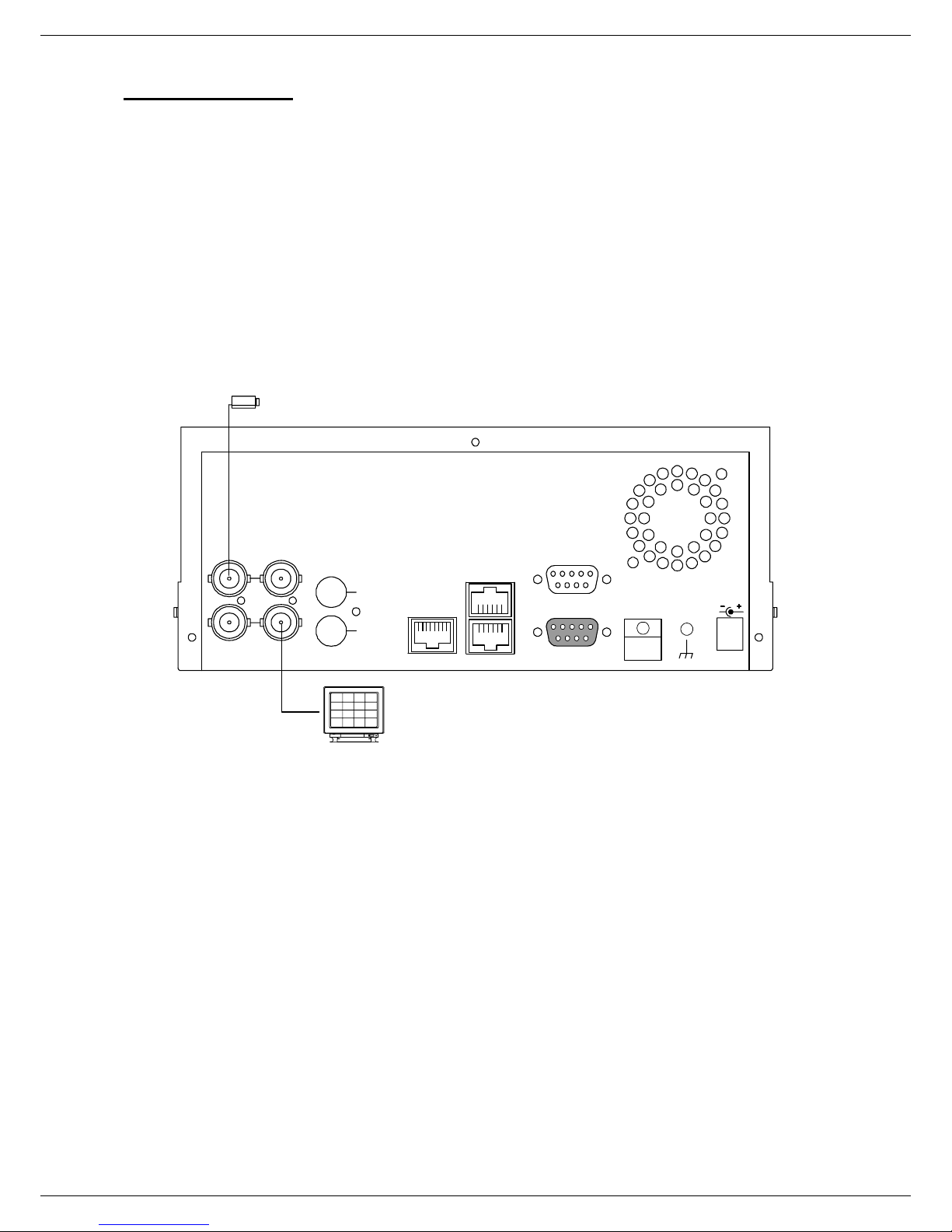
3.1 Basic Connection
CONNECTING WITH A SINGLE CAMERA
Please set the MULTIPLEXER option to OFF on the REC SETTING page in the setup menu
when it is connected with a single camera. (Please refer to section 5.1 MULTIPLEXER option)
Camera
FROM MUX
MAIN MONITOR
VIDEO
AUDIO
TO
MUX'S VCR IN
OUT
IN
TO
MONITOR
OUT
IN
ETHERNET
10/100
RS-485
RS-232
ALARM
I/O
DC12V
Monitor
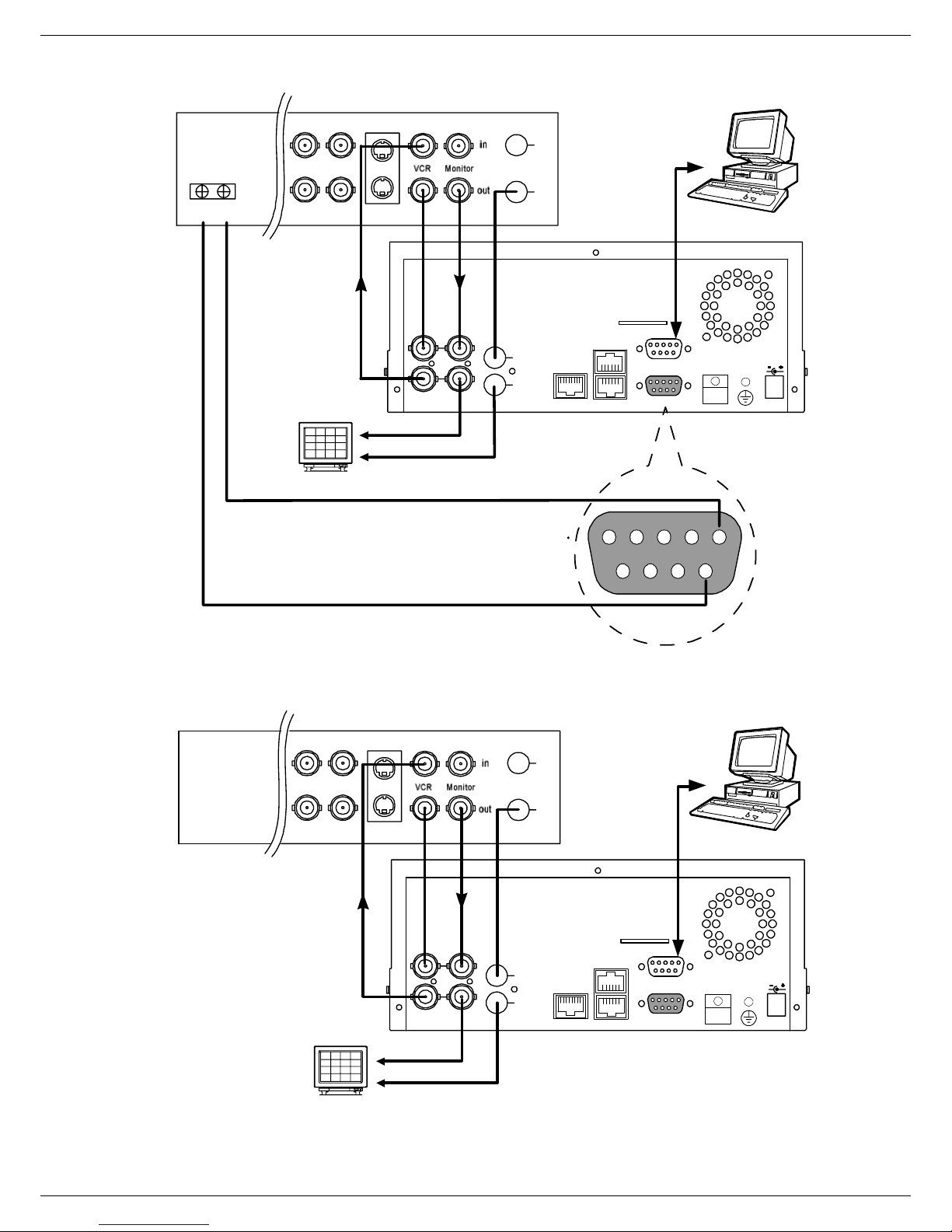
CONNECTING WITH A MULTIPLEXER
When connecting the DGR201 to a multiplexer, go to the REC Setting page in the setup menu
and turn the MULTIPLEXER option ON when it is connected to the multiplexer. (Please refer to
section 5.1 MULTIPLEXER option)
CONNECTING WITH A QUAD
When connecting the DGR201 to a Quad, go to the REC Setting page in the setup menu and turn
the MULTIPLEXER option to OFF. (Please refer to section 5.1 MULTIPLEXER option)
10
Multiplexer
IN
Audio
OUT
Trig In
S-video
PC
Monitor
Quad
Video in
Audio in
S-video
VIDEO
TO
MUX'S VCR IN
FROM MUX
MAIN MONITOR
IN
OUT
MONITOR
AUDIO
TO
SWITCH OUT
IN
OUT
GROUND
IN
Audio
OUT
ETHERNET
10/100
RS-485
SD Card
ALARM
RS-232
I/O
DC12V
12345
6789
PC
Monitor
Video in
Audio in
VIDEO
TO
MUX'S VCR IN
FROM MUX
MAIN MONITOR
IN
OUT
MONITOR
SD Card
AUDIO
IN
OUT
TO
ETHERNET
10/100
RS-485
ALARM
RS-232
I/O
DC12V
11
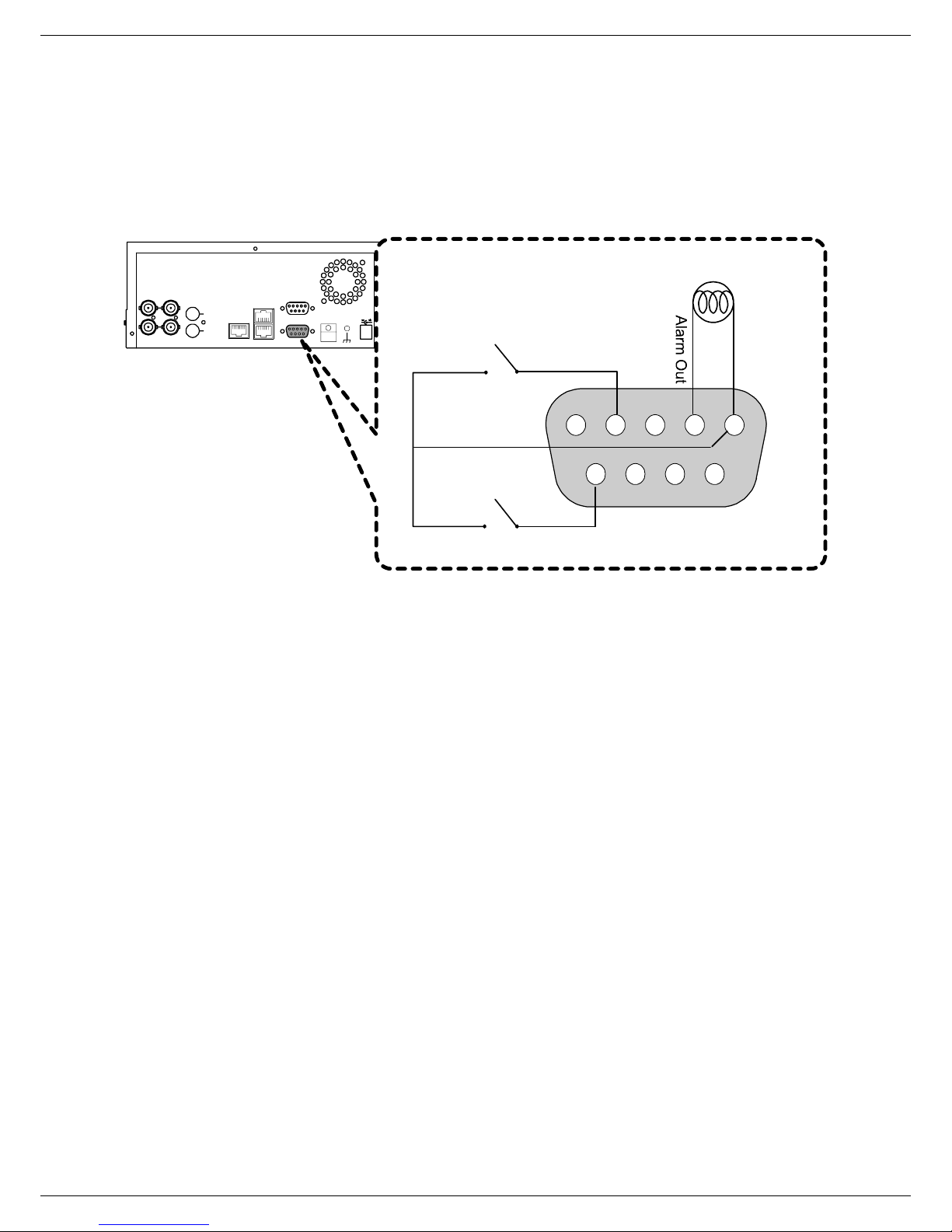
ATTACHING AN EXTERNAL DEVICE TO DGR201
Connect an alarm out, alarm input, and a peripheral device as shown in the diagram below.
FROM MUX
MAIN MONITOR
VIDEO
MUX'S VCR IN
AUDIO
IN
OUT
TO
IN
OUT
TO
MONITOR
ETHERNET
RS-485
10/100
RS-232
ALARM
I/O
DC12V
Alarm Reset
(Normally Open)
Lamp
12345
Ground
6789
Alarm in
(Normally Open)
12

3.2 Hard-Disk Drive Installation
The DGR201 is equipped with two hard disk drive compartments. The unit usually comes with one
hard-disk drive installed in the internal HD1 compartment, which is default-configured as a master. A
second hard-disk drive can be installed in the HD2 compartment (Mobile). Contact your distributor or
installer for more information.
NOTE: If an internal hard disk has not been installed, and the HD2 compartment (Mobile) is to be used,
the DGR201 must be set to the HD2 USAGE option to REC (Please refer to section 5.5). The
jumper-settings arrangement of installed hard-disk drives for the system (Table 3.2 A.) are shown in the
tables below.
Table 3.2 A. The jumper settings of hard disk drives in the system
Location Jumper
IDE 1 Compartment HD 1 Master (Default)
IDE 2 Compartment HD 2 Master
Table 3.2 B. Compatible hard-disk drives
Manufacturer Model Capacity Rotation
Western Digital
Seagate
Maxtor
NOTE: Hard-disk drives not shown on this list have not been tested by the engineering team
and are not recommended for use with this product. For the latest updated list on the
recommended hard disk drives, please visit www.digimerge.com
WD800AB 80GB 5400 RPM
WD1200AB 120GB 5400 RPM
WD800BB 80GB 7200 RPM
WD1200BB 120GB 7200 RPM
WD1800BB 180GB 7200 RPM
ST380020A/P 80GB 5400 RPM
ST340810A/P 40GB 5400 RPM
4A160J0-1A 160GB 5400 RPM
4R080L0-1 80GB 5400 RPM
6Y120L0-1 120GB 7200 RPM
6Y200P0-1A 200GB 7200 RPM
6Y250P0-1A 250GB 7200 RPM
.
13
3.3 System Information
You can display system settings information as shown on Table 3.3 A below by pressing the Display
button
at any time.
In the PLAYBACK mode, the recorded video information will be displayed.
In the LIVE or RECORDING mode, the Manual Recording information is displayed.
(NOTE: When the DGR201 is displaying a decoded image from a multiplexer, first switch the unit to the
encoded image displaying by pressing the Monitor button
button
LED is off). Each sequential press of the Display button displays a different message
(video switching swiftly and the Monitor
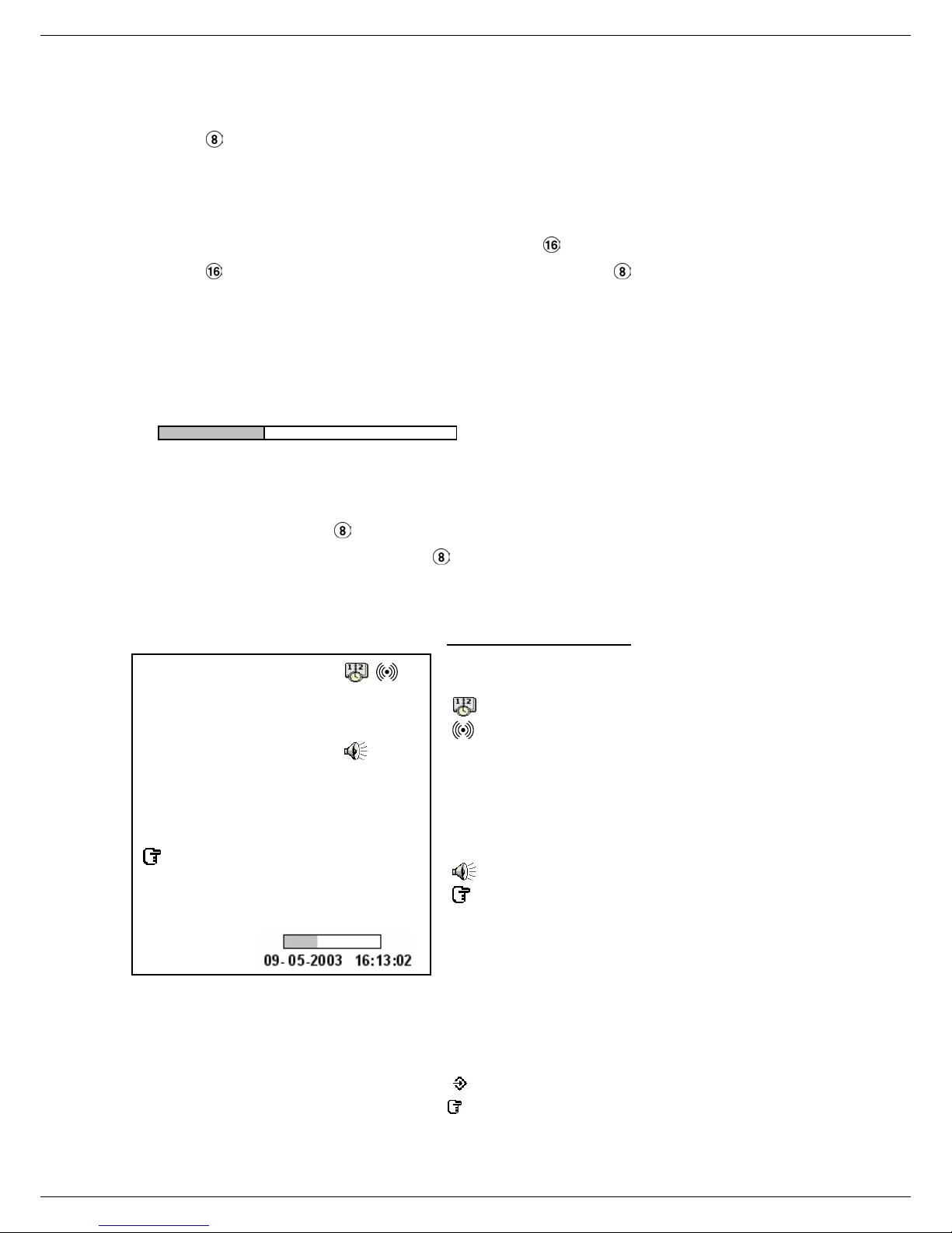
detailed in the following example. By default, the unit displays time, date, and an indicating bar of
capacity status on a monitor as shown next.
Default display
(Capacity Used) (Capacity Remaining)
09- 05-2003 16:13:02
(Date) (System Time)
Press the Display button
default display. Press the Display button
once; the DGR201 will display the following sample message plus the
again; the unit will not display any OSD message. Press
the button one more time to back to the default display.
Table 3.3 A. Description of Table 3.3 A
1+ 2: 59G 12.4 HR
QUALITY: BEST NTSC
RATE: 6 HR 20 F/S
MUX : OFF 9K
HD P SIZE POS
1 Y 20 G 39.5% P
2 Y 39 G 0.0% R
IP : 192 . 168 . 1 . 90
(1+2: 59G): Total capacity of installed hard disk, 59 GB
(12.4 HR): Total 12.4 hour recording time available
): Timer record activated
(
): Alarm record activated
(
(QUALITY: BEST): Record quality setting, BEST
(NTSC): NTSC system
(RATE: 6 HR): Setting of Record time mode, 6 hours
(20 F/S): Record speed setting, 20 fields/sec
(MUX: OFF):
( ): Audio function activated
): Indicate which HDD is activated
(
(9K): The image file size
(HD): Hard disk Compartment
(P): Y Hard disk installed; . No hard disk installed
(SIZE 20G): The capacity of the installed hard disk
(POS): Percentage of system; R: Recording; P: Playback
(IP : 192 . 168 . 1 . 90): Setting of
Only connected to a single camera.
the Ethernet
communication, 192.168.1.90
(
)
: External signal
(X): Cannot operate at now
14

3.4 Updating System Software
If the system software of the DGR201 needs to be upgraded, please take the following steps to safely
update it.
Important: Before carrying out the following procedures, please ensure the SD card is working
and the file of system software is intact
1. Turn off the DGR201.
2. Insert the SD card into the built-in SD slot located at the front of the unit.
3. Hold down the
Up and Down buttons simultaneously, and then turn on the unit.
4. Keep holding down the buttons until the DGR201 sounds a tone and display the message “ XXXXXX
BYTES READ”. Now the DGR201 is updating the system software, which will take approximately 90
seconds to process.
5. Restart the unit when the device sounds a tone twice and displays the message “PLEASE RESTART”
The process is complete.
NOTE: If the DGR201 does not power up after updating the software, ensure that the file on the SD
card is functioning properly and the file is intact and repeat steps 1 through 5.
6. Verify the version of the system software. (Please refer to section 5.6 VERSION option)
A-rec T-recDISK
SD Card
Power Display SetupSearch EnterMonitor Play Pause Stop
Warning: Interrupting the software update process during the transfer will cause the
system to freeze.
13 12
15
Rec

4. BASIC OPERATIONS
This section outlines the basic operating instructions for the DGR201.
4.1 Configuring Recording Settings
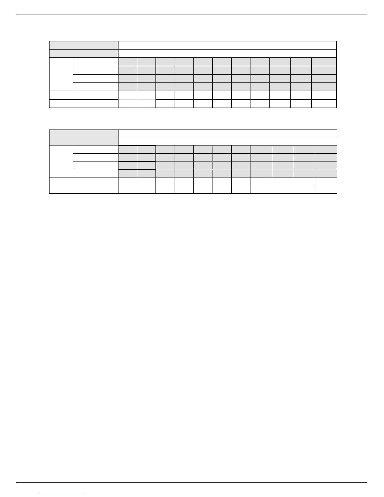
Recording Time settings (Recording Rate and Picture Quality Setting)
The Recording time available on DGR201 is dependent on 3 variables, the image size, recording rate,
and capacity of the hard-disk drives. Generally, the DGR201 comes with a built-in hard-disk drive for
continuous recording from one to four weeks under most recording conditions. The table below shows
the possible recording times based on an 80GB hard-disk drive at certain refresh rates and the
corresponding image quality. With one or more hard-disk drive(s) in operation, the recording time can be
determined using the table below in accordance with your requirement. For a NTSC unit, for example, if
the unit is set to record images with BEST quality at a 60 fps record rate, normally a 80GB hard-disk
drive will be filled in 15 hours (See the gray area in the table). If the total capacity of the hard disk drives
is 240GB using the same refresh rate and picture quality, the recording time will be approx. 45 hours (3
times the rate of an 80GB hard-disk drive).
Set up the REC Time Mode when a multiplexer is connected
If a multiplexer is connected, for optimum image recording and playback, the record speed of the
multiplexer must be correctly adjusted to match the DGR201 and set the MULTIPLEXER option on the
setup menu to ON. This can be done by either of methods detailed below.
Connect the SW. OUT terminal in 9-PIN D-SUB connector on the rear panel of the DGR201 to the
multiplexer’s trigger contact. The DGR201 will provide the timing signal (Negative/Falling) to the
multiplexer. Thus, if the DGR201 changes the recording speed, the multiplexer will automatically adjust
the record to match. A 2-hour and 4-hour timing signal in NTSC or a 3-hour and 6-hour one in PAL is
constantly negative/falling.
NTSC (MUX ON)
Audio ON
BEST
Image
Quality
Refresh Rate (Field/Sec) 60 30 20 12 5.5 2.4 1.22 0.71 1/4 1/6 1/8
REC Time Mode 2 hr 4 hr 6 hr 12 hr 24 hr 48 hr 96 hr 168 hr 480 hr 720 hr 960 hr
HIGH
STANDARD
BASIC
Possible Recording Time HDD=80GB ( hour )
- - 26.8 44.4 95.8 208.5 380.6 598.5 - - -
- - 33.4 55.3 118.8 255.7 459.6 708.9 - - -
- - 44.4 73.2 156.1 330.5 580.0 869.5 - - -
- - 66.1 108.4 227.6 467.3 785.9 1124.0 - - -
16
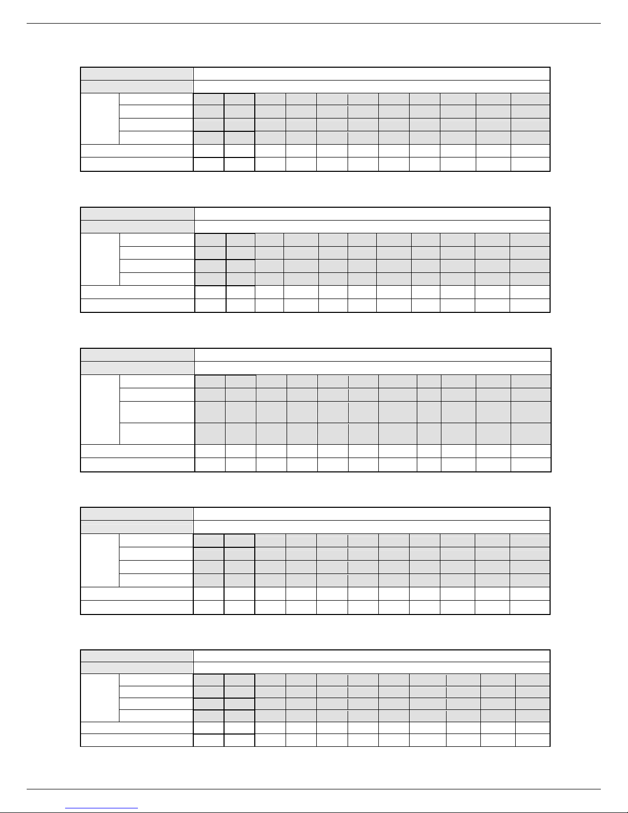
NTSC (MUX ON)
Audio OFF
BEST
Image
Quality
Refresh Rate (Field/Sec)
REC Time Mode
HIGH
STANDARD
BASIC
Possible Recording Time HDD=80GB ( hour )
15.0 18.0 27.1 45.1 99.3 225.9 442.7 768.0 2177.7 3262.0 4346.4
18.0 22.5 33.8 56.4 124.2 282.3 553.4 960.1 2722.1 4077.6 5433.0
22.5 30.1 45.1 75.3 165.6 376.5 737.9 1280.1 3629.5 5436.8 7244.0
30.1 45.1 67.7 112.9 248.4 564.7 1106.9 1920.2 5444.3 8155.2 10866.1
60 30 20 12 5.5 2.4 1.22 0.71 1/4 1/6 1/8
2 hr 4 hr 6 hr 12 hr 24 hr 48 hr 96 hr 168 hr 480 hr 720 hr 960 hr
NTSC (MUX OFF)
Audio ON
BEST
Image
Quality
Refresh Rate (Field/Sec)
REC Time Mode
HIGH
STANDARD
BASIC
Possible Recording Time HDD=80GB ( hour )
- - 35.6 53.1 104.2 216.2 387.2 603.9 - - -
- - 44.4 66.1 129.0 264.9 467.3 715.1 - - -
- - 58.9 87.4 169.4 342.1 589.3 876.4 - - -
- - 87.4 129.0 246.4 482.7 797.3 1131.7 - - -
60 30 **20 **12 **5.5 2.4 1.22 0.71 1/4 1/6 1/8
2 hr 4 hr 6 hr 12 hr 24 hr 48 hr 96 hr 168 hr 480 hr 720 hr 960 hr
NTSC (MUX OFF)
Audio OFF
BEST
Image
Quality
Refresh Rate (Field/Sec)
REC Time Mode
HIGH
STANDARD
BASIC
Possible Recording Time HDD=80GB ( hour )
15.0 18.0 36.1 54.2 108.4 234.9 451.8 777.1 2186.7 3271.1 4355.4
18.0 22.5 45.1 67.7 135.5 293.6 564.7 971.3 2733.4 4088.9 5444.3
22.5 30.1 60.2 90.3 180.7 391.5 753.0
30.1 45.1 90.3 135.5 271.0 587.3 1129.5
60 30 **20 **12 **5.5 2.4 1.22 0.71 1/4 1/6 1/8
2 hr 4 hr 6 hr 12 hr 24 hr 48 hr 96 hr 168 hr 480 hr 720 hr 960 hr
1295.
1 3644.6 5451.8 7259.1
1942.
7 5466.9 8177.8 10888.6
PAL (MUX ON)
Audio ON
BEST
Image
Quality
Refresh Rate (Field/Sec)
REC Time Mode
PAL (MUX ON)
Image
Quality
Refresh Rate (Field/Sec)
REC Time Mode 3 hr 6 hr 9 hr 12 hr 24 hr 48 hr 96 hr 168 hr 480 hr 720 hr 960 hr
HIGH
STANDARD
BASIC
Audio OFF
BEST
HIGH
STANDARD
BASIC
Possible Recording Time HDD=80GB ( hour )
- - 26.8 44.4 78.9 145.3 268.6 432.8 - - -
- - 33.8 55.8 98.9 181.0 330.7 524.6 - - -
- - 45.6 75.3 132.5 240.0 430.0 666.0 - - -
- - 66.7 109.5 190.9 339.4 589.5 879.2 - - -
50 25 17 10 5.5 2.9 1.52 0.88 1/4 1/6 1/8
3 hr 6 hr 9 hr 12 hr 24 hr 48 hr 96 hr 168 hr 480 hr 720 hr 960 hr
Possible Recording Time HDD=80GB ( hour )
15.4 18.0 27.1 45.1 81.3 153.6 298.1 515.0 1816.2 2719.9 3623.5
18.0 22.8 34.2 57.0 102.7 194.0 376.6 650.6 2294.2 3435.6 4577.1
22.8 30.9 46.4 77.4 139.4 263.3 511.1 882.9 3113.6 4662.7 6211.7
30.9 45.6 68.4 114.1 205.4 388.0 753.3 1301.2 4588.5 6871.3 9154.2
50 25 17 10 5.5 2.9 1.52 0.88 1/4 1/6 1/8
17
PAL (MUX OFF)
Audio ON
BEST
Image
Quality
Refresh Rate (Field/Sec)
REC Time Mode
PAL (MUX OFF)
Image
Quality
Refresh Rate (Field/Sec)
REC Time Mode
HIGH
STANDARD
BASIC
Audio OFF
BEST
HIGH
STANDARD
BASIC
NOTE: Recording times on the tables above are estimated. For actual available recording
time of a recording configuration, please refer to the system information of the
DGR201. (Please refer to section 3.3 system information for more details.)
NOTE: No audio function at the refresh rate in NTSC: 60 fields/sec ~ 30 fields/sec, 1/4
fields/sec ~ 1/8 fields/sec.
No audio function at the refresh rate in PAL: 50 fields/sec ~ 25 fields/sec, 1/4
fields/sec ~ 1/8 fields/sec.
NOTE: An actual recording fields number could be less than the Refresh Rate on the table
above.
Possible Recording Time HDD=80GB ( hour )
- - 35.6 53.1 87.4 153.4 275.9 439.1 - - -
- - 44.9 66.7 109.5 190.9 339.4 532.0 - - -
- - 60.5 89.8 146.5 252.8 441.0 674.8 - - -
- - 88.3 130.3 210.5 356.8 603.4 889.5 - - -
50 25 **17 **10 **5.5 2.9 1.52 0.88 1/4 1/6 1/8
3 hr 6 hr 9 hr 12 hr 24 hr 48 hr 96 hr 168 hr 480 hr 720 hr 960 hr
Possible Recording Time HDD=80GB ( hour )
15.4 18.0 36.1 54.2 90.3 162.6 307.2 524.1 1825.3 2728.9 3632.5
18.0 22.8 45.6 68.4 114.1 205.4 388.0 662.0 2305.6 3447.0 4588.5
22.8 30.9 61.9 92.9 154.9 278.8 526.6 898.4 3129.1 4678.2 6227.2
30.9 45.6 91.3 136.9 228.2 410.9 776.1 1324.0 4611.3 6894.1 9177.0
50 25 **17 **10 **5.5 2.9 1.52 0.88 1/4 1/6 1/8
3 hr 6 hr 9 hr 12 hr 24 hr 48 hr 96 hr 168 hr 480 hr 720 hr 960 hr
** : For NTSC and Mux Off Mode, recording rate 20F/S would be actually 15 F/S, 12F/S
would be actually 10 F/S, 5.5 F/S would be actually 5F/S.
For PAL and Mux Off Mode, recording rate 17F/S would be actually 12.5 F/S, 10F/S
would be actually 8.3 F/S, 5.5 F/S would be actually 5F/S.
( This adjustment is to avoid image shaking during playback at the same speed )
18

4.2 Recording Operations
This section details the way to record video into hard-disk drives. Before commencing with the recording
function, please configure the recording setting properly according to your needs.
4.2.1 Manual Recording
To start a manual record while the DGR201 is in live display mode, perform the following…
(1) press the REC button
programmed recording settings. The monitor should display a flashing REC message and the
REC button
(2) Press the STOP button
(3) To access the recorded video, please refer to section 4.4.
LED will turn on indicating the DGR201 is recording.
to record video onto the hard disk drive with the corresponding
to stop recording at any time.
4.2.2 Timer Recording
Timer (or scheduled) recording provides two periods of time each day in a weekly table that
programs the DGR201 to turn on and off at specified times. This way the DGR201 will start and
stop recording according to the programmed schedule. To program the DGR201 to record
according to a schedule, perform the following steps…
(1) Press the Setup button
(2) Select the CLOCK / TIMER option and press the Enter button
TIMER page.
(3) Select the TIMER-SET.
to enter the MAIN MENU.
to enter the CLOCK /
(4) Press the Enter button
(5) ● Use the “<”
stop time.
● The time is displayed in a 24-hour clock format.
(6) After the programming for the scheduling is completed, press the Enter button
OK to save the setting or select CANCEL to leave the page without saving the settings.
(7) To activate the programmed recording schedule, set the REC ENABLE to ON. When the
scheduled recording is on, the red Timer Record LED
record, set the option to OFF.
(8) Press the STOP button
resume recording, press the REC button
NOTE: You can proceed to start the scheduled recording from the current time if it is in the
scheduled interlude as soon as setting is completed, and come out from menu to start
recording.
and “>” buttons to locate the specific day/hour/minute for the start and
to enter the REC SCHEDULE table.
and select
will be on. To disable the timer
during the scheduled recording to stop recording at any time. To
to proceed.
19
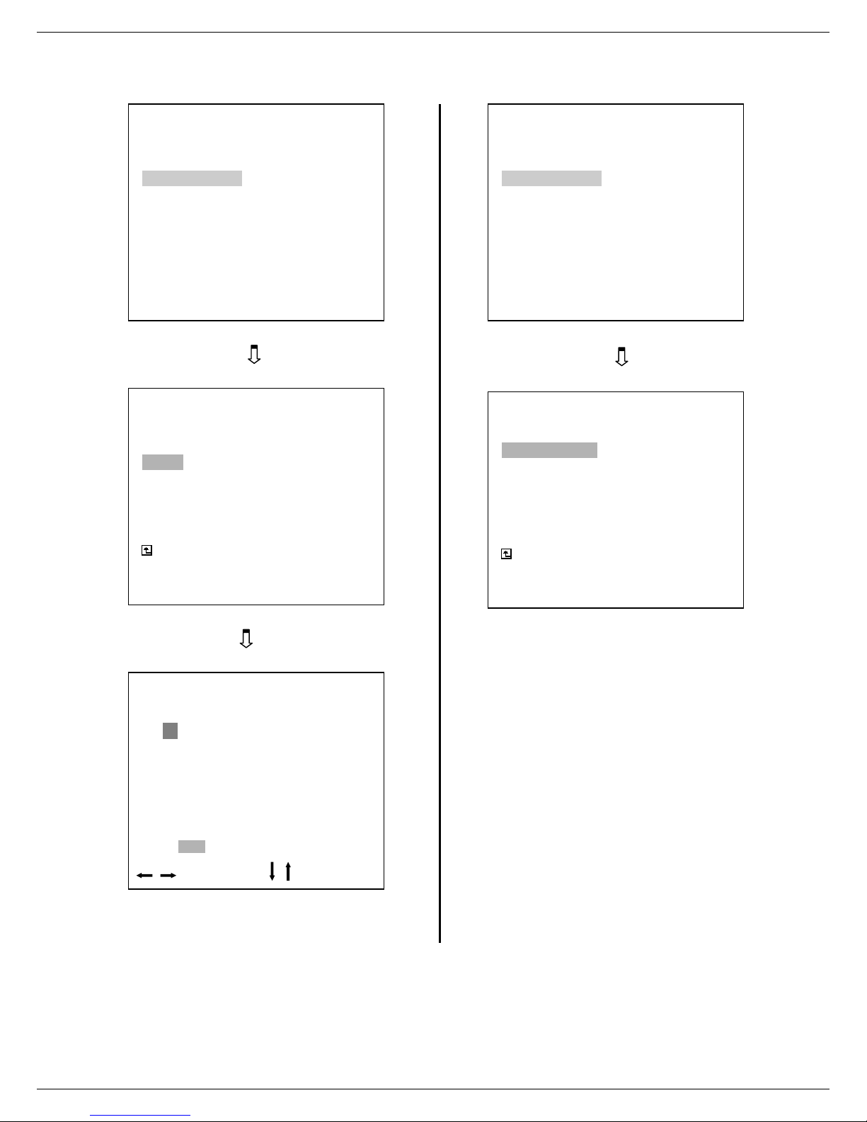
RECORD
ALARM
CLOCK / TIMER
COMMUNICATION
DISK
SYSTEM
GOTO CLOCK / TIMER PAGE
CLOCK : SET
REC ENABLE : OFF
TIMER : SET
MAIN PAGE
SET REC SCHEDULE
START END
S : 00:00-00:00 00:00-00:00
M: 00:00-00:00 00:00-00:00
T : 00:00-00:00 00:00-00:00
W: 00:00-00:00 00:00-00:00
T : 00:00-00:00 00:00-00:00
F : 00:00-00:00 00:00-00:00
S : 00:00-00:00 00:00-00:00
OK CANCEL
MAIN MENU
CLOCK / TIMER
REC SCHEDULE
TO MOVE
START END
TO CHANGE
MAIN MENU
RECORD
ALARM
CLOCK / TIMER
COMMUNICATION
DISK
SYSTEM
GOTO CLOCK / TIMER PAGE
CLOCK / TIMER
CLOCK : SET
REC ENABLE : OFF
TIMER : SET
MAIN PAGE
TIMER REC ENABLE
20
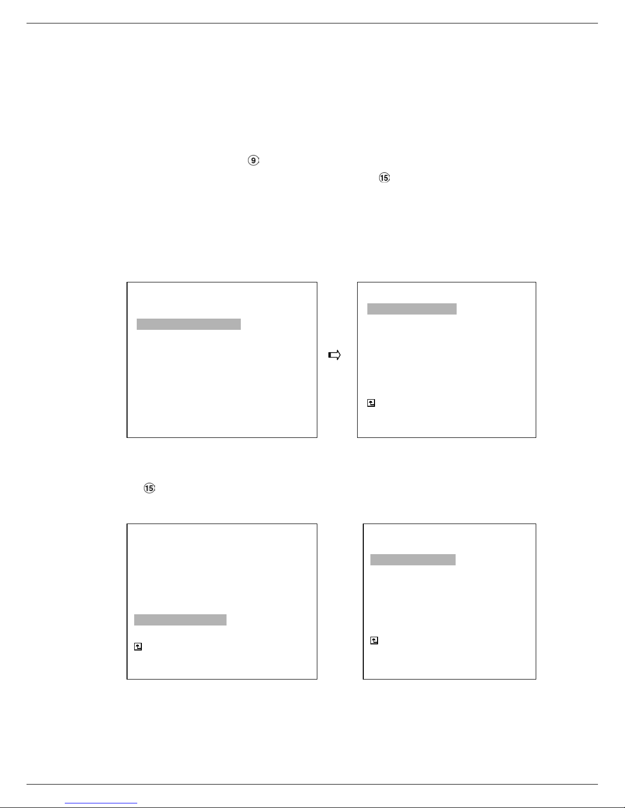
4.2.3 Alarm Recording
When setting up the DGR201 to trigger a recording from an alarm input, the following options are
available…. REC RATE, REC QUALITY, AUDIO, ALM TYPE, ALM DURATION, and
PRE-ALARM settings, (please refer to section 5.2 for a detailed description of each option).
To access these options, perform the following…
(1) Press the Setup button
(2) Select the ALARM feature and press the Enter button
option menu.
(3) Set the desired REC RATE, REC QUALITY, ALM TYPE, and ALM DURATION for use. If audio
is required, set AUDIO to ON. If pre-alarm recording is required, set PRE-ALARM to ON.
(4) To activate the alarm recording, set ALM OPERATION to ON. To deactivate it, set ALM
OPERATION option to OFF.
RECORD
ALARM
CLOCK / TIMER
COMMUNICATION
DISK
SYSTEM
GOTO ALARM PAGE
(5) To activate the motion alarm recording, Select MOTION SETTING and press the Enter button
MAIN MENU
to enter the MAIN MENU.
to enter the ALARM SETTINGS
ALARM SETTING
ALM OPERATION : OFF
REC RATE : 20F/S
REC QUALITY : BEST
AUDIO : OFF
ALM TYPE : NO
ALM DURATION : 0 SEC
PRE- ALARM : OFF
MOTION SETTING
MAIN PAGE
ALARM REC ENABLE
to enter the MOTION SETTING PAGE, set MOTION ENABLE TO ON, and set a suitable
sensitivity according to the video sources.
ALARM SETTING
ALM OPERATION : OFF
REC RATE : 20F/S
REC QUALITY : BEST
AUDIO : OFF
ALM TYPE : NO
ALM DURATION : 0 SEC
PRE- ALARM : OFF
MOTION SETTING
MAIN PAGE
ALARM REC ENABLE
MOTION SETTING
MOTION ENABLE : ON
SENSITIVITY : 3
REGION : SET
MAIN PAGE
SET MOTION DETECTION
21
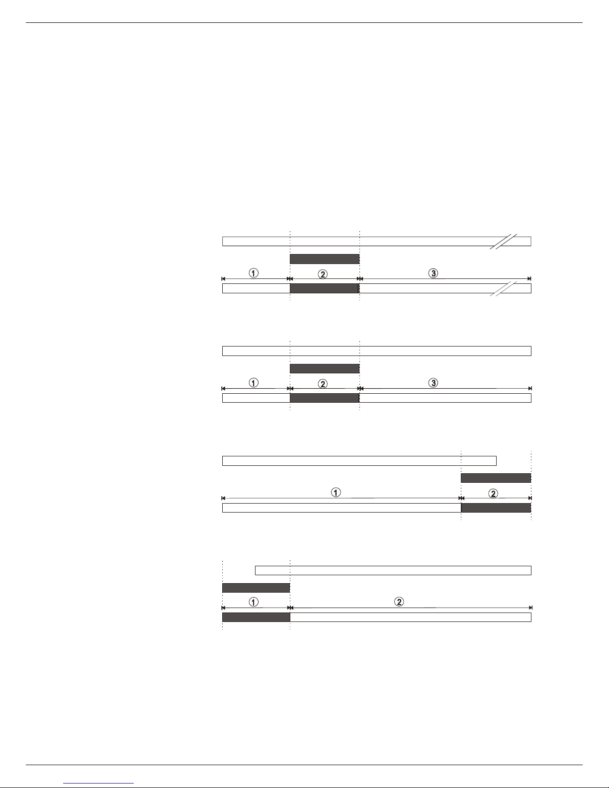
4.2.4 Externally triggered Recording
By connecting the RECORD IN of ALARM I/O on the rear panel of the DGR201, you can
activate/deactivate the recording function of the DGR201. The file will be identified with a prefixe
“R”. Please refer to section 2.3 for more details.
NOTE: The status of recording operations when an alarm takes place are shown in the
diagrams below.
Manual or Externally
1
Triggered Recording
Alarm Takes Place
Actual Recording
2
3
4
Timer Recording
Alarm Takes Place
Actual Recording
Timer Recording
Alarm Takes Place
Actual Recording
Timer Recording
Alarm Takes Place
Actual Recording
Speed
Speed
Speed
Speed
Normal Alarm Normal
Normal Alarm Normal
Normal Alarm
Alarm Normal
22

4.3 Playback Viewing Options
This section shows you how to operate the fast, slow, and single-picture playback functions, and details
what the unit will show in the different Playback viewing modes.
During the playback of a file, the DVR will flash “PLAY” on the monitor and the PLAY button
will be on.
A. From REC mode to Playback mode
(In live mode, pressing the PLAY button
REC→〔STOP〕→〔PLAY〕……………………………… Plays the last recorded file
〔Play to the end of the file〕… The unit will show an end of file message (use
〔STOP〕→〔PLAY〕…………Play the file from the stop position
B. Search to play back a particular recorded video
Search→〔PLAY〕………………………………………… Play a selected file
〔Play to the end of the file〕………… The unit will show an end of file message
〔STOP〕→〔PLAY〕………………… Play the file from the stop position
C. Play Back From The Oldest Data
〔Stop: Press the “STOP” button for three seconds〕→〔PLAY〕..play back from the beginning of the
will play the video that was last recorded.)
search functions or rewind to replay the file if
required)
(Search again or rewind to replay the file if
required)
HDD recorded data
LED
4.3.1 Fast Forward/Reverse
There are 7 speeds available for playback: 1x, 2x, 4x, 8x, 16x, 30x and 100x.
During playback, turn the Shuttle Dial clockwise or counter-clockwise to increase the playback speed
in the corresponding direction. The speed of the playback is dependent on the amount the shuttle dial
is turned.
Forward: Turn the Shuttle dial
speed faster than the recorded speed.
Reverse: Turn the Shuttle dial
direction at a speed faster than the recorded speed.
Normal: Release the Shuttle dial
* You can also operate by using “<” button
clockwise to view the recorded video in the forward direction at
counter clockwise to view the recorded video in the reverse
to return to the normal speed of playback.
and “>” button .
23
 Loading...